Design, Manufacturing, and Testing of an Active
Twist Rotor
by
SangJoon Shin
B.S., Aerospace Engineering, Seoul National University (1989) M.S., Aerospace Engineering, Seoul National University (1991)
Submitted to the Department of Aeronautics and Astronautics
in partial fulfillment of the requirements for the degree of
Master of Science in Aeronautics and Astronautics
at the
MASSACHUSETTS INSTITUTE OF TECHNOLOGY
June 1999
@
Massachusetts Institute of Technology 1999. All rights reserved.Author ... ... Department of Aeronautics and Astronautics
May 12, 1999
Certified by ...
Kill ~V~~Cj
Carlos E. S. Cesnik Assistant Professor of Aeronautics and Astronautics Thesis Supervisor LA Accepted by ... Chairman, .1.. -. .-. ... ... Jaime Peraire Department Graduate Committee
MASSACHUSETTS INSTITUTE OF TECHNOLOGY
JUL 1 5 1999
LIBRARIES
Design, Manufacturing, and Testing of an Active Twist Rotor by
SangJoon Shin
Submitted to the Department of Aeronautics and Astronautics on May 12, 1999, in partial fulfillment of the
requirements for the degree of
Master of Science in Aeronautics and Astronautics
Abstract
An Active Twist Rotor (ATR) is developed for future implementation of the individual blade control for vibration and noise reduction in helicopters. The rotor blade is integrally twisted by direct strain actuation using active fiber composites (AFC). In order to design and analyze an active blade, a general framework is proposed. A multi-cell thin-walled active composite beam model is developed. The model is validated against a combination of other theoretical models and experimental data. Actuation trend studies are conducted by examining the formulation, and the results are verified by numerical examples. Design requirements are proposed by combining general ones applicable to passive model-scaled rotor blade and specific ones to the current ATR blade. A design flowchart is established for the current design task of the ATR blade since it enables systematic handling of a number of the parameters. Several different concepts of ATR candidates are suggested, and compared with each other with regard to the requirements. Other design aspects such as manufacturing simplicity and cost-effectiveness are also considered in the process. The final design is selected, and final adjustments are added to it in order to simplify its manufacturing. A prototype blade is manufactured in accordance with the final design. A couple of testing articles are fabricated in advance to the full-span prototype in order to debug the manufacturing process. Various tests are conducted with the testing articles and the final prototype to verify the design and correlate with model predictions. A maximum static tip twist of 1.5' (peak-to-peak) was achieved at half of the designed operating electric field before five of the 24 AFC packs failed. Electrical breakdown of the embedded active material caused degradation of twist actuation in the prototype blade, and the causes are presently under investigation. The ATR prototype blade is leading to a complete fully-articulated four-blade active twist rotor system for future wind tunnel tests.
Thesis Supervisor: Carlos E. S. Cesnik
Acknowledgments
I greatly appreciate Dr. Carlos E. S. Cesnik, who is my advisor, for his guidance and supervision throughout the entire process of this thesis. Without his encouragement, this thesis would not exist. I would also like to express my gratefulness to Dr. Nesbitt W. Hagood and Dr. Steven R. Hall, for sharing their profound knowledge with me regarding any problems occurred during the process.
I am grateful to Dr. John Rodgers and Mr. Eric Prechtl, for their help and effort on the manufacturing and experiments. Special thanks to Mr. John Kane for letting me work in the excellent laboratory environment.
I would definitely like to thank Dr. W. Keats Wilkie and Mr. Paul Mirick, for the financial support and kind help on the manufacturing, and also Mr. Matthew L. Wilbur for supporting with CAMRAD II results.
I would also thank Mr. Woo-Sok Chang and Dr. Jae-Hyuk Oh, for their encour-agement and friendship, which helped me to carry out this thesis.
I would appreciate my parents for the endless love and support, and also, my sister, brother-in-law, and brother. Especially, I would like to thank my fiancee, JeeYoung, for her encouragement and understanding.
Contents
1 Introduction
1.1 Helicopter Vibrations . . ... 1.2 Helicopter Vibration Alleviation . ...
1.3 Previous Work Related with Integral Twist Actuation . 1.4 Present Work ... ...
2 Active Blade Structural Analysis
2.1 Overview ... ... 2.2 Cross-section Analysis . . ... 2.3 I-D Beam Analysis . . ...
2.3.1 Extended active beam equations . . . .. 2.3.2 Inertial properties . ...
2.4 Three-dimensional Stress Recovery Formulation . . . .
3 Validation of the Proposed Active 3.1 Overview ...
3.2 Box-Beam Case . ...
3.3 Single-Cell Active Blade Results . 3.3.1 Cross-section results . . . 3.3.2 Beam results . . . . 3.4 Two-Cell Active Blade Results ..
4 Study on the Actuation Constants
Structural Model 23 .. . . . 23 .. . . . . 24 . . . . . 26 . . . .. . 27 29 . . . .. . 29 .. . . . 30 .. . . . 37 .. . . . 38 .. . . . . 43 . . . . . 45 47 .. . . . 47 .. . . . 48 .. . . . 49 . . . . . . . . . 49 .. . . . . 52 .. . . . 54
4.1 Overview ... ... ... 59
4.2 Analytical Examination of Actuation Components . ... 60
4.3 Numerical Examination of Actuation Components . ... 63
4.4 Twist-Related Relationship from the Present Formulation ... 65
4.5 Twist Actuation Results ... ... 67
4.5.1 Two-cell box beam cases ... .. 67
4.5.2 ATR blade cases ... ... 68
5 Design Requirements and Procedure 75 5.1 Overview ... ... ... 75
5.2 Design Requirements ... ... 75
5.3 Design Flowchart ... ... .. 81
5.4 Structural Integrity Substantiation ... 85
6 ATR Design Results 89 6.1 Overview ... ... ... 89
6.2 Active Spar Candidates and Variations . ... 90
6.2.1 Analysis of the active spar candidates . ... 90
6.2.2 Variations of the active spar candidates . ... 95
6.3 Analysis of the Active Fairing Candidates . ... 96
6.4 Analysis of the Active Box Beam Candidates . ... . 100
6.5 Selection of the Final Design and Improvement . ... . 104
7 ATR Prototype Blade Manufacturing 107 7.1 Overview ... ... ... 107
7.2 Miscellaneous Items ... ... 107
7.2.1 Integral blade root ... ... 107
7.2.2 AFC packs ... ... ... 108
7.2.3 Flexible circuit ... ... 110
7.2.4 Foam cores and ballast weights . ... . 111
7.4 Prototype blade ...
7.5 Summary of Manufacturing Issues and Recommendations . . . .
8 ATR Prototype Blade Testing 8.1 Overview ... ... 8.2 Blade Root Test . ...
8.3 Blade Torsional Stiffness Measurement 8.4 Bench Actuation Test . . . ... 8.5 Frequency Response Test . . . .
9 Conclusions and Recommendations
9.1 Summary ... ... 9.2 Conclusions ... 9.3 Recommendations . ... . . . . . . . . .... A Cross-Sectional Formulation B 1-D Blade Formulation C Material Properties
D Detailed Dimensions of the ATR Prototype Blade
E Activities Listing of the Prototype Blade Manufacturing
113 117 119 119 120 121 124 126 129 129 131 132 135 139 141 143 151 . . . . . . . . . . . . . . . . . . . . . . . . . . o . . . . . . . . . . . . . . . . . . . . . . . . . . . . . . . . . . . . . ... .. .
List of Figures
1-1 Aerodynamic environment in forward flight . ... 24
2-1 Two-cell thin-walled closed-section beam . ... 31
2-2 Branches for integration of a two-cell thin-walled cross section . . . . 36
2-3 Blade frames ... . 39
3-1 Two-cell thin-walled box beam definition . ... 49
3-2 Single-cell active blade cross section (NACA 0012) . ... 51
3-3 Single-cell active blade tip twist ... . . 52
3-4 Single-cell active blade twist distribution . ... 53
3-5 Schematic diagram of the complete CH-47D active blade section [28] . 55 3-6 Schematic diagram of the CH-47D spar [28] . ... 55
4-1 Flapwise deflection of the single-cell active blade under bending actuation 64 4-2 Baseline configurations of two-cell box beams . ... 67
4-3 Schematic diagram of the ATR blade design . ... 69
4-4 Twist actuation result of two-cell ATR blade . ... 70
4-5 Baseline configuration of D-spar single-cell derivative beam (dimen-sions are in inches) ... ... . . 71
4-6 Baseline configuration of single-cell airfoil-shaped derivative beam (di-mensions are in inches) ... ... 71
4-7 Twist actuation result of D-spar single-cell beam . ... 72
4-8 Twist actuation result of single-cell airfoil-shaped beam ... 73
5-2 Flowchart of the ATR blade design tasks . ... 82
5-3 Flowchart of the ATR blade design tasks (cont'd) . ... 83
5-4 CAMRAD II prediction of flapwise bending moment ... 86
5-5 CAMRAD II prediction of chordwise bending moment . ... 87
5-6 CAMRAD II prediction of torsional moment . ... 87
6-1 Schematic diagram of the several ATR design candidates ... . 90
6-2 Schematic diagram of the active spar candidate (all dimensions are in inches). ... ... ... ... 91
6-3 Twist actuation trend for the active spar ATR candidates with respect to the number of AFC packs embedded across the thickness .... . 92
6-4 Schematic diagram of the active box beam candidate (all dimensions are in inches) ... ... ... 100
6-5 Schematic diagram of the final selected design . ... 106
7-1 Drawing of 3-dimensional blade root stack . ... 108
7-2 Detail of the blade root construction ... 109
7-3 Final AFC pack design used in the ATR prototype blade ... . 109
7-4 AFC packs being inserted during the prototype manufacturing . . . . 110
7-5 Strain gauges attached upon the foam cores . ... 114
7-6 Blade mold in which the spar assembly is sitting with dummy fairing backup and strain gauge wires are extracted at root along the small trough ... ... . 115
7-7 Prototype spar sitting inside the blade mold clamped with the fixtures at the leading edge and the tip ... .. 116
7-8 Final ATR prototype blade ... .... 117
8-1 Testing article showing catastrophic failure under tensile loading . . . 121
8-3 ATR prototype blade clamped at the testing rig with the laser sensors illuminating the reflecting strips (weights hung at the end of cables for torque the blade tip are also shown). . ... 123 8-4 Torsional stiffness results for the spar and full blade - comparison
be-tween measurements and theoretical results . ... 123 8-5 Distribution diagram of each specific AFC pack in the prototype blade 125 8-6 Actuation results of the ATR prototype blade having only 19 out of
the 24 AFC packs working (voltage levels are peak-to-peak, no DC offset) 126 8-7 ATR prototype blade tip twist response as function of applied electric
field (no DC offset) ... .. .. .. . 127 8-8 ATR prototype blade bench response of embedded strain gauges vs.
AFC excitation frequency ... ... 128 8-9 ATR prototype blade bench tip twist actuation response vs. AFC
excitation frequency . ... . . . . . 128
D-I Cross-section schematic of the ATR blade and the dimension of the ballast weights ... . . . . . ... . 144 D-2 Cross-section schematic of the front spar foam core (dimensions include
oversize) . . . . . . . . . . . 145 D-3 Cross-section schematic of the fairing foam core (dimensions include
oversize) ... .... ... ... . 145 D-4 Spanwise distribution of the 24 AFC packs at the top and bottom
surface of ATR prototype blade ... .. 146 D-5 Drawing of the three E-Glass skin plies which cover the whole span (all
dimensions are in inches) . ... ... . . 147 D-6 Drawing of the auxiliary S-Glass pieces which fill the gap between
in-board/outboard end and the first/last AFC pack space (all dimensions are in inches) ... ... 147 D-7 Drawing of six-layer flexible circuit showing the location of each solder
D-8 Location of the strain gauge bridges along the span of ATR prototype
List of Tables
3.1 Properties of AS4/3506-1 Graphite/epoxy - "L" direction is along the fibers and "N" is normal to laminate . ... 48 3.2 Non-zero stiffness results (N, N m, N m2) for two-cell box beam (1
extension; 2 torsion; 3, 4 bending) ... . 49 3.3 Material properties used in the single-cell active blade (Qij are the
laminate reduced stiffness of the actuator pack) . ... 50 3.4 Non-zero stiffness (N, N m, N m2) and forcing vector (N, N m) results
for airfoil-shaped cross section - (Kij: 1 extension; 2 torsion; 3, 4
bending) . ... ... ... . . . . . . . . .. 51 3.5 Non-zero stiffness (N, N m, N m2) and forcing vector (N, N m) results
for CH-47D D-spar only - (Ki3: 1 extension; 2 torsion; 3, 4 bending) . 56 3.6 Non-zero stiffness (N, N m, N m2) and forcing vector (N, N m) results
for CH-47D active blade section (front D-spar + fairing) - (Kj: 1
extension; 2 torsion; 3, 4 bending) ... . 56 3.7 Twist actuation rate comparison for CH-47D active blade (D-spar only
and full cross-section: analyses and experiment) . ... 57
4.1 Analytical expressions of the actuation components for single-cell ac-tive beam ... . ... 61 4.2 Numerical comparison of actuation vector components for airfoil-shaped
beam ... ... ... ... 64 4.3 Analytical results of two-cell box beam . ... 68
5.2 Structural properties of the existing baseline rotor blade (at 0.5R) . . 76
5.3 Summary of rotor blade scaling parameters . ... 78
6.1 Lay-up information of four active spar candidates . ... 91
6.2 Analysis results of four active spar candidates (1 cantilevered boundary condition at root) ... ... 93
6.3 Comparison of candidate No. 2 against requirement . ... 94
6.4 Lay-up information of the variations of active spar candidates . . .. 97
6.5 Analysis results of the variations of active spar candidates ... 98
6.6 Ultimate strength data of AFC material . ... 98
6.7 Lay-up information of the active fairing candidates . ... 99
6.8 Analysis results of the active fairing candidates . ... 99
6.9 Lay-up information of the active box beam candidates . ... 101
6.10 Analysis results of the active box beam candidates . ... 103
6.11 Result of the final design compared with requirements ... . 105
8.1 Tensile load test on 3/4-radius blade spar (blade station in inches) . . 120
8.2 Sequence and condition of AFC pack failure during the actuation test 125 8.3 Twist actuation of the ATR prototype blade (o/m, 2, 000 Vpp/0 VDC) 125 9.1 Hover test plan for the ATR prototype blade (TDT at Langley) . . . 133
C.1 Properties of the AFC packs ... .... 141
C.2 Properties of the composite materials used in the ATR protype blade 141 C.3 Capacitance history of the AFC packs . ... 142
Nomenclature
a Ae Aei A(s) A(a)(s), C(a)(s) b B B(s) C(s) Cba CBa C d dkij el Eijkl Ek fa fI f,,, fa fM,, fP,, fHiglobal frame attached to the hub inner area enclosed by all sections inner area enclosed by the i-th cell only axial stiffness in the shell frame
actuation contribution to the shell energy functional undeformed reference frame of the blade
deformed reference frame of the blade
coupling between axial and shear stiffness in the shell frame shear stiffness in the shell frame
transformation matrix from a to b transformation matrix from a to B rotation matrix, product of Cab and CBa
characteristic dimension of the beam cross section piezoelectric electromechanical coupling tensor two-dimensional Hookean tensor
unit vector [1, 0, O]T Hookean tensor electric field vector external forces vector
FI beam axial force
F(a) actuation component of beam axial force
FB internal force column vector in the B frame F(a) actuation column vector for internal force 91(s) warping due to axial strain
g2(s), g93(s) warping due to bending strain
Geff effective wall shear stiffness
GLT shear modulus in the ply coordinate
G(s) torsion-related warping
h thickness of the shell surface
HB angular momentum column vector
I 3 x 3 inertial matrix
[J] Jacobian matrix in the Newton-Raphson formulation
K kinetic energy density per unit span of the blade
[K] general 6 x 6 stiffness matrix
K,3 beam stiffness components
L length of the shell
Al, length of the i-th spanwise beam element
m blade mass per unit span length
m external moment vector
M1 beam torsional moment
M2, M3 beam bending moments
MIa) actuation component of beam torsional moment
M2a), M ) actuation components of beam bending moments MB internal moment column vector in the B frame
M(a) actuation column vector for internal moment
n normal vector of an arbitrary point perpendicular to the surface
Nc PB r Tt r, R s, ( E sijkl t Ua u (x) Ui, , Fi Mi, Pi, Hi U v1, vs, v~ v(a)(S) Va VB W1 Wa X() X (t)
stress tensor in the shell frame linear momentum column vector
position vector of an arbitrary point in the surface projection of the position vector r on t
projection of the position vector r on n radius of curvature of the shell middle surface
coordinate with respect to the middle surface point along the surface
elastic compliance tensor at constant electric field tangent vector of an arbitrary point along the surface displacement vector measured in the a frame
displacement field of the cross-section reference point constant vectors of the corresponding quantities at each node i
energy density of a three-dimensional elastic body approximation of the energy density U
displacement field of an arbitrary point in the shell frame actuation contribution to the out-of-plane displacement initial velocity of a generic point on the a frame
linear velocity column vector in the B frame out-of-plane warping function
initial angular velocity of a generic point on the a frame virtual work of applied loads per unit span
beam axial coordinate
column matrix of the unknowns in one-dimensional beam formulation
steady components of the unknowns X
y, z Cartesian coordinates with respect to the reference point in the cross section
Za arbitrary vector Z represented with respect to a frame
Zb arbitrary vector Z represented with respect to b frame ZB arbitrary vector Z represented with respect to B frame
Zjk = Zi ejk
, a generalized strain column vectors
-3, shell in-plane strain
A 3 x 3 identity matrix
(i) mechanical strain tensor Ei7 total strain tensor
ij) non-mechanical strain tensor
0 rotation vector expressed in terms of Rodrigues parameters Slocal coordinate of each beam finite element
JA virtual action at the ends of the beam and at the ends of the time interval
JIIa variational quantity of total potential energy in the a frame rTij JII over the i-th element
p weight density of the blade
Pij shell surface curvature
aij stress tensor
O(x) twist angle of the cross section
shell energy per unit middle surface area
ith-order approximation of the shell energy functional blade azimunth angle
I(E 3) quadratic terms in the electric field
QB angular velocity column vector in the B frame
derivative with respect to the beam span coordinate, xl ( ) ds anticlockwise integration along all the sections
fj(
) ds anticlockwise integration along the i-th cell section only * geometrically exact kinematical quantity in the a frame ( ) boundary values of the corresponding quantitiesChapter 1
Introduction
1.1
Helicopter Vibrations
The rotor system is the main source of helicopter vibrations, and the resulting vibra-tory load becomes a dominant factor of reducing the life of fatigue-critical components. These vibrations also limit the performance of the helicopters such as forward flight speeds, and tend to decrease payload due to the addition of extra vibration-alleviation devices.
The primary source of the rotor system vibration is oscillatory airloads acting on the rotor blades, and these oscillatory airloads are caused by the unsteady
aerody-namic environment of the main rotor especially in forward flight.
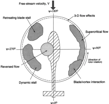
A typical forward flight aerodynamic environment of the helicopter main rotor is illustrated in Figure 1-1, where helicopter flight velocity adds to the blade element rotating velocities on the advancing side (4' = 90'), and subtracts from it on the retreating side (4 = 2700). Therefore, the aerodynamic environment is characterized
as follows: high tip Mach number on the advancing side, and blade stall effects on the retreating side. A reverse flow region is also generated on the retreating side. Such a complicated environment results in an instantaneous asymmetry of the aerodynamic loads acting among the blades at different azimuthal locations. The vibratory response of a flexible blade structure adds more complexity on the air loads asymmetry. This asymmetry is transmitted to the fuselage at the frequency of N/rev,
Free-stream velocity, V
W=180o
Retreating blade stall 3-D flow effects
Supercritical flow
W2700 1=-900
direction of
rotor rotation)
Reversed flow
Dynamic stall Blade/vortex interaction
W_Oo
Figure 1-1: Aerodynamic environment in forward flight
where N is the number of blades in the rotor. This mechanism becomes a primary source of fuselage excitation.
The rotor blades usually have a built-in twist which is to relieve the lift difference between the inboard and outboard sections when hover, and it gives an advantage of increasing payload. However, the larger the rotor blades have the built-in twist, the more severe fuselage vibrations become in forward flight. Therefore, helicopter designers traditionally take a trade-off value of the built-in twist considering between the hover performance and the forward flight vibrations.
1.2
Helicopter Vibration Alleviation
There has been much effort to alleviate the vibration from the early stages of heli-copter development [1, 2]. The vibration alleviating methodologies employed by the helicopter designers may be categorized into the following three groups:
1. Varying passive structural properties of the rotor system or fuselage by tuning its dynamic characteristics;
2. Employing passive or active vibration absorbing devices either at the rotating system or the fixed system;
3. Direct modification of the excitation forces, principally aerodynamic forces to reduce vibration.
Among these methodologies, employing vibration absorbers has been widely adopted by the helicopter industry, and the absorbers produce counteracting inertial and damping forces [3]. However, such mechanisms introduce significant cost, in terms of weight and complexity, as well as potential aerodynamic performance degradation. Therefore, an effort to modify directly the excitation forces has been suggested, that is, to eliminate or reduce vibrations by modifying unsteady aerodynamic forces acting on the rotor blades.
Higher harmonic control (HHC), one of such ideas, is accomplished by manipu-lating a conventional swashplate to enable blade pitch control of a higher multiple frequency than an integer multiple of rotating frequency, i.e., (kN + 1)/rev. Individ-ual blade control (IBC) installs a pitch actuator in each blade rather than modulating the swashplate, and allows for blade pitch control at arbitrary frequencies.
HHC with a conventional swashplate presents limitations associated with weight penalty and hydraulic power requirement as well as severe fatigue induced at actuator components. On the contrary, by using active material actuators installed directly in the blade, IBC can be implemented without great increase in weight and
complex-ity [4]. Such active material actuators, employed either by discrete flap-actuation mechanisms or embedded along the blade to induce twist, also have the advantage of requiring only electrical power to operate. Especially, the induced-strain twist rotor based on embedded active fiber composites (AFC) is mechanically simple and does not require additional device into the rotating system. Recent experimental research on the strain-induced twist rotor blade has shown that high levels of twist actuation are achievable [5, 6].
1.3
Previous Work Related with Integral Twist
Actuation
There have been several approaches in the literature to take advantage of active ma-terials for individual blade control [2, 4]. The one of interest in the present study is the integral actuation through the use of active fiber composites (AFC) with inter-digitated electrodes [7]. This actuator concept provides a feasible way of integrally actuate a rotor blade instead of the direct use of piezoceramic crystals.
The same concept using piezoceramic crystals was studied by Chen and Chopra [8, 9] in a 6-ft diameter 2-bladed Froude-scaled rotor model with banks of piezo-ceramic crystal elements in ±45' embedded in the upper and lower surfaces of the test blade. They also developed a simple composite beam model with piezoelectric actuator in order to predict the static response. There have been improvements in the actuation levels by using dual-layer actuators and the maximum experimental tip twist actuation obtained was of the order of 0.50 still below the 10 to 2' necessary for the possible vibration reduction applications.
On the other hand, preliminary results from the AFC concept obtains the level of authority needed from the actuator. Basic material characterization and proof of concept of an integral twisted-actuated rotor blade have been under investigation at MIT's Active Materials and Structures Laboratory [5, 10]. Experimental work related with active twist rotor blades based on such AFC plies has also been conducted. In a bench test of a 1/16th Froude-scaled model rotor blade, duPlessis and Hagood [11] have reported achieving static twist of up to 1.4'. Rodgers, Hagood and Weems [5] also have reported achieving twist actuation rates of up to 1.3'/m in the prelimi-nary testing of a 1/6th Mach-scaled active CH-47D rotor blade. In the consecutive hover testing, it was also proved that the concept of AFC technologies is enough for withstanding the combined steady centrifugal loads and unsteady aerodynamic loads acting on the blade at the worst loading condition [6].
Several analytical models were developed to analyze and design such active twist rotor blades (Song and Librescue [12]; duPlessis and Hagood [11]; Wilkie, Belvin and
Park [13]), and these models are all based on the single-cell closed-section passive beam structural model suggested by Rehfield [14] with its assumed displacement field in the cross-section. However, there is no guarantee for consistent accuracy on the result of a non-asymptotical (passive) composite cross-sectional model theory (see, for example, Cesnik and Hodges [15]).
Wilkie, Belvin and Park [13] have presented an aeroelastic analysis of a helicopter rotor blade in hover with active twist capabilities, and showed a possibility of vibration reduction with a simple scheme of open-loop twist control. Wilkie [16] also suggested a closed-loop control of twist actuation as future research to reduce the vibrations.
Derham and Hagood [17] examined the vibration reduction potential of a proposed 1/6th Mach-scaled model rotor using a modified version of Boeing Helicopter's pro-prietary comprehensive rotor analysis code. This analysis indicated that 70% to near 100% reductions in the primary frequency component of the vertical hub shear load could be obtained by applying an appropriately phased twisting actuation moment.
1.4
Present Work
The objective of this thesis is to consistently analyze, design, and manufacture a prototype Active Twist Rotor (ATR) blade in order to explore helicopter vibration reduction capabilities. As the first step, an analytical model of an active beam struc-ture is developed to analyze various design candidates. The analysis is for a two-cell thin-walled closed-section composite beam with anisotropic active plies embedded in it. Within the analytical model developed, the static and dynamic behavior of the ac-tive beam structure is analyzed through a two-step process: a linear two-dimensional analysis over the cross section, and a geometrically non-linear beam analysis along the span.
A verification process is conducted in each step of the analytical model develop-ment. The correlation effort with other existing analytical models and experimental results obtained from small-scaled active rotor blades are performed for cross-sectional stiffness constants, actuation (forcing vector) constants, and global blade structural
behavior. Studies are conducted to better understand the discrepancies between the Rehfield-based models and the present asymptotical one, as well as the design paradigm associated with the relation between torsional stiffness and twist actuation. With the aid of the developed model, structural stiffness and inertia design of the prototype ATR blade are carried out. Blade dynamic characteristics, such as twist actuation and natural frequencies, are guaranteed within the requirements. For the static strength requirement, a comprehensive rotorcraft analysis code, CAMRAD II, is used to simulate critical forward flight conditions and the peak values of the vibratory loads within the blades are extracted.
Several candidates with different geometrical distribution of active material are proposed and tested in terms of satisfying the requirements. A final design is selected which also takes into account the cost effectiveness associated with AFC's. A pro-totype ATR blade was manufactured and bench test was also followed to assess the actuation performance and structural integrity.
Chapter 2
Active Blade Structural Analysis
2.1
Overview
An analytic formulation for a two-cell thin-walled composite beam with integral anisotropic piezoelectric actuators is derived to design and analyze an active twist helicopter rotor blade. It is an asymptotically correct formulation stemming from shell theory.
The present analysis extends previous work done for modeling generically passive blades [15, 18, 19]. The approach is based on the two-step solution of the original three-dimensional blade representation by means of an asymptotical approximation: a linear two-dimensional cross-sectional analysis and a nonlinear one-dimensional global analysis [15]. The resulting model is expected to correctly predict the behavior of he-licopter blades, accounting for the presence of different materials (passive and active) and an approximation of the actual blade shape.
The cross-sectional analysis revises and extends the closed form solution of a thin-walled, multi-cell asymptotic formulation presented by Badir [20]. The variational-asymptotical method [21] is used to formulate the stiffness constants of a two-cell cross section with the active plies consisting of piezoelectric fibers. This cross-sectional analysis is a specialized case of the general framework established in [15]. It provides the expressions for the asymptotically-correct cross-sectional stiffness constants in closed form, facilitating design-trend studies. These stiffness constants will then be
used in a beam finite element discretization of the blade reference line. The exact intrinsic equations for the one-dimensional analysis of rotating beams considering small strains and finite rotations developed by Hodges [18] and implemented by Shang and Hodges [22] is extended to take into account the changes in the constitutive relation. Subject to external loads, active ply induced strains, and specific boundary conditions, the one-dimensional (beam) problem can be solved for displacements, rotations, and strains of the reference line. Finally, these results could be combined with information from the cross-sectional analysis in a set of recovering relations for stress/strain distribution at each ply of the blade. This structural representation serves the basis for an aeroelastic blade design model.
2.2
Cross-section Analysis
Stiffness constants for an anisotropic thin-walled two-cell beam is obtained from a variational-asymptotical formulation originally presented by Badir [20]. Herein, the original formulation is expanded to deal with the effects associated with the presence of active materials, the final expressions for the stiffness constants are corrected of misprints, and a validation study of such formulation (not presented in [20]) is pre-sented in Chapter 3. In this section, the main steps of the cross-sectional analysis derivation is presented based on a linear beam formulation. Even though the one-dimensional (1-D) beam formulation that follows is intrinsically nonlinear, there is no loss of generality at this level to use a geometrically linear beam assumption.
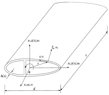
Consider a slender thin-walled elastic cylindrical shell as shown in Fig. 2-1. It is assumed that
d h h
-
<
, ) 1, 1 1 (2.1)L d R
where L is length of the shell, h is thickness, -h() < < h(s), R is the radius of
curvature of the middle surface, d is a characteristic cross-section dimension, and s is defined in Fig. 2-1.
Figure 2-1: Two-cell thin-walled closed-section beam
r on t and n are expressed on the Cartesian and curvilinear coordinates as
dr dy dz t b2 + b3 ds ds ds dz dy n = txbl1= b2 - b3 (2.2) ds ds dy dz rt = r't=y +z-ds ds dz dy rn= r n= y - z ds ds
and bi are shown in Fig. 2-3.
The energy density of a three-dimensional (3-D) elastic body is a quadratic form of the strains
U E= ijkl(m) (m) (2.3)
where i, j, k, 1 = 1, 2, 3; the material properties are expressed by the Hookean tensor
Ezjk
the non-mechanical strain 6( m), i.e., ij
(M) (nm) (2.4)
62 - 3
and the total strain can be written in terms of two-dimensional (2-D) strain measures as
Ei= + Pzj (2.5)
where 7ij is in-plane strain components, and p., is the shell curvature.
Considering the non-mechanical strain coming only from piezoelectric actuation, the expression of non-mechanical strain 6nm) from a linear piezoelectric constitutive
relation [23] is given as
E, = SzjklUkl + dkijEk (2.6) where Ej> is the total strain tensor, s kl is the elastic compliance tensor at constant electric field, aij is the stress tensor, dk,3 is the piezoelectric electromechanical coupling tensor, Ek is the electric field vector.
The first term in the right-hand side of Eq. (2.6) represents mechanical strain E(m) and the second one represents the non-mechanical strain, which will be denoted by E) since it results from actuation only.
The 3-D strain energy is then minimized with respect to Ei3, (the through-the-thickness stress components are considerably smaller than the remaining components) in order to obtain the formula corresponding to shell
U i minU U = ID ^6E () () (2.7)
where D3 6
is the 2-D Hookean tensor (see, for example, [20]), and a, 3, 7, 6 = 1, 2.
From practical considerations, one may assume that only E3 exists (the notation
for the electric field follows conventional piezoelectric notation. Note, however, that in the case of AFC, the so-called E3 runs along the piezo fibers). The 2-D strain
expression becomes
(M) (a) (2.8)
= ~ + PacP - d3acE 3
Substitute Eq. (2.8) into Eq. (2.7) and integrate over the thickness J to get a shell energy ( per unit middle surface area
2( = {< DPr ' > 7,p - 2 < DPr'd3,6E 3 > }7,6
+ 2{< DOJ6 > ~p- < DaPr6 d3 6E3 >}pyj (2.9)
+ < DaY6 2 > PCpY6 + (E3)
where
f+h(s)/2
< (e) >= f (e) d (2.10)
_-h(s)/2
The function I(E 3) in Eq. (2.9) represents the quadratic terms in the electric field.
Since the electric field is prescribed in the actuation problem, this term does not enter in the further derivation of the beam stiffnesses and actuation constants.
From the variational-asymptotical method [21], the shell energy functional after the first-order approximation reduces to
2I1 = min 2D (2.11)
Y22
= {A", - 2A(a)}111 + 2B71 1Y1 2 +- {C712 - 2C(a) }12 - XF2(E3)
The variables A, B, and C represent the axial, coupling, and shear stiffness, respec-tively, while the actuation contribution to the energy is represented by the new terms
A(a), C(a), and P2(E3), i.e.
< D1122 >2
A = < D 1111 >
-< D22 22 >
B = 2 < D 11 12 122
)>1122
C = 4 (< D1212 > -A(a) = < D1 1yd 3 E3 C(a) = 2 (< D12^/6d 3,1 i < D1 2 2 2 > 2 < D2222 > > - < D22-6d3,6E 3 > < D22 2 2 > < D1 2 2 2 > < D2 2 2 2 >
The shear flow N12 is found to be constant and the hoop-stress resultant N2 2
vanishes S ( = (A(s)71 0(2712)
2
+ B(s)71 2) - A(a)(s) 711 + C(s)7 12) 1 (a) (s) 2 = constantleading to a warping function wl associated with the first-order approximation as follows
Ow1 4 C 2 dy
Owl 4 (constant)- 2 C , 2 (a) _ dy
U sing the single-value condition ds
Using the single-value condition on the function wl
dz
- ds (2.14)
wlds (2.15)
for the i-th closed cell (I for first cell and II for second cell) determines the expression of the "constant" in Eqs. (2.13) and (2.14).
The displacement field from the second-order approximation becomes
V1 = U1(X) - y(s) u2(x) - z(s) u3(x) +
+ G(s) q'(x) + g1(s) u' (x) + g2() U (X) + 9g3() U '(X) + (2.16) + (x)r, dz + U3) ds (2.12) Nil N12 (2.13) + VI) (s) dy ds - Of rn
dz dy
= () ( -
n(x)
- ¢(x)rtds ds
where
Jo{2g a) - C(a)(-)}c(T)dT
with s = 0 - sl (left branch)
a) {2(ga) -ga)) - C(a)(T)}c(T)dT
va) (S) s
with s = si -+ s2 (web)
{2ga) - C(a)(T)}c(T)dT
with s = s2 - S3 (right branch)
(a) _ 2{(b2 b5)) + b2f 2a)
1
(bl + b2)(b2 + b5) - bi
(a) __ 2{(b1 + b2) fa) + b2fa)} (2.17)
S (b + b2)(b2 + b5) - b(
f(a) = cC(a)ds
f a) cC(a) ds
with b,, c defined in the Appendix A, and each integration being evaluated along the corresponding branch of the two-cell cross section. The integration subscripts I and
II denote anticlockwise integration over the left and right cell, respectively (Fig. 2-2).
The strain field associated with Eq. (2.16) is
711 = _(x) - y (s) U2 ) - Z(S) U'(x)
dG dgl dg2 dg3 ,, dva) (2.18)
2-12 = - + rn) u 1d +3 -- (2.18)
ds n ds 1 ds ds ds
22 = 0
The constitutive relations can be written in terms of stress resultants and kine-matic variables by relating the traction F1, torsional moment M1, and bending
mo-s=0 ,s=s3
S=SI
Figure 2-2: Branches for integration of a two-cell thin-walled cross section
ments M2, M3 to the shear flow and axial stress as follows:
M = aJ l2 7n = N12 rn(s) ds
M2
a(2 //)J
0ii = N1 l z(s) ds M3 - 11 y(s) dds = - Nil y(s) dsSubstituting Eq. (2.13) and Eq. (2.18) into Eq. (2.19) one gets
F1 = J NI ds
= [A {u' - yu" - zu/}
dg3
ds
1 dG 2 ds S+ dg, ds Udva ) A(a)]ds ds ds = N11 ds(s) <dds
z(s) dds (2.19)-= J{A y1 + Byl2 - A(a)} ds
+ dg2 //
1 (--13
u 2 (2.20)B dv (a)
2 ds - A(a)) ds
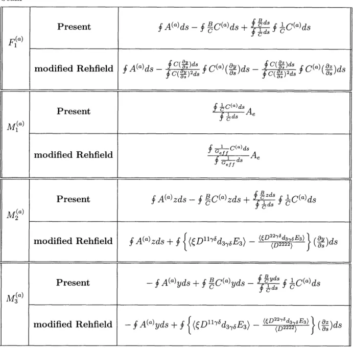
and similarly with the other three moment equations. The first four terms in the final part of the right-hand side of Eq. (2.20) correspond to the stiffness coefficients for an anisotropic two-cell beam. (Detailed expressions of Kij and relevant parameters are in the Appendix A.) The last term (following those) results from piezoelectric actuation, and can be regarded as a forcing vector. The general form of the constitutive relation can be written as F K11 K 12 K13 K14 U F(a) M1K K1 2 K 2 2 K 2 3 K 2 4 ' M.a) M(a)(2.21) M2 K 13 K 2 3 K 3 3 K 3 4 3 2 M3 K1 4 K 2 4 K 3 4 K 4 4 UIa)
Explicit expressions of piezoelectric actuation contributing to the constitutive relation are given by
F (a) = {A(a) B C(a) ds + 2g B 2(a) (a) ds
- 2g1 ds + 2g2 d
M1a) = -2gia) Aei - 2g2a) AeII (2.22)
M2a) = {A(a) B C(a)}z ds - 2gia)
J
z ds - 2g2a) C dsd3 + 21 I ds
where integral without any subscripts
f
denotes over-all-section evaluation, which isa summation of evaluations over s = 0 -- s , s = sl -- 82 and s = s2 -- 83.
2.3
I-D
Beam Analysis
A nonlinear one-dimensional global analysis considering small strains and finite rota-tions is presented here as a direct expansion of the mixed variational intrinsic formu-lation of moving beams originally presented by Hodges [18], and implemented in [22]. The notation used in this section is based on matrix notation and is consistent with the original work of [18] and [22]. Some steps are repeated here to help clarifying the modifications in this extended formulation.
2.3.1
Extended active beam equations
As shown in Fig. 2-3, a global frame its axes labeled as al, a2 and a3. The
denoted b, with its axes labeled as bl, denoted B, with its axes labeled as B1,
Any arbitrary vector Z represented by converted to another basis like
denoted a is rotating with the rotor, with undeformed reference frame of the blade is
b2 and b3, and the deformed reference frame
B2 and B3, though not shown in the figure.
its components in one of the basis may be
Zb baZa, ZB = CBaZa (2.23)
where Cba is the transformation matrix from a to b, and CBa is that from a to B. There are several ways to express the transformation matrices. Cba can be expressed in terms of direction cosines from the initial geometry of the rotor blade, while CBa contains the unknown rotation variables.
As described in details in [18], the variational formulation is derived from Hamil-ton's principle which can be written as
jt2
j[6(K
- U) + SW] dxldt = 6At1 0
(2.24)
where tl and t2 are arbitrarily fixed times, K and U are the kinetic and potential energy densities per unit span, respectively. 6A is the virtual action at the ends of the beam and at the ends of the time interval, and SW is the virtual work of applied loads per unit span.
Taking the variation of the kinetic and potential energy terms with respect to VB and QB, the linear and angular velocity column vectors, and with respect to ' and i, the generalized strain column vectors,
FB =
(U
_ PB a=Y ) P B = a V(K (2.25) HB = 8a<TKT TKa3
a2
a1
Figure 2-3: Blade frames
where FB and MB are internal force and moment column vectors, and PB and HB are linear and angular momentum column vectors, respectively.
The geometrically exact kinematical relations in the a frame are given by
y* = CBa (Cabel +a) -
e
* = ba 0' (2.26)
1+ 4-°
V* = CBa (Va + ia + aUa)
, = cba 1 2 + CBaWa
where Ua is the displacement vector measured in the a frame, 0 is the rotation vector
expressed in terms of Rodrigues parameters, el is the unit vector [1, 0, O]T, A is the 3 x 3 identity matrix, va and Wa are the initial velocity and initial angular velocity
of a generic point on the a frame.
( )
operator applied to a column vector is defined as:0 -Z 3 Z2
S= Z3 0 -Z 1 (2.27)
-Z 2 Z1 0
y and r, to satisfy the geometric equations in Eq. (2.26).
Manipulating the equations according to [22], one can obtain the a frame version of the variational formulation based on exact intrinsic equations for dynamics of moving beams as
I
t 1t26Ia dt = 0 (2.28)
where
6I, a= {ju UTCTCabFB +6U [(CTCabpB) ± LaCTCabB]
--IT -T
T+ T6 CCabM - 6 CT Cab( + y)FB
+ 7 6ab MB- a B
-- TT
+ a[(CTCabHB)* + CT CabHB + CTcabVBPB]
- 6PF, T[CT Cab(el - 21 - ab1 a Ua
-6Ma(A + )Cab -6MO
2 4
+ 6 (T CabVB - Va - OaUa) - JPa Zia 0 OO
T
+ SH ( - - )(CTCabQB -a)
2 2
- - 6uifa aHa -a Tjma}dx
a Ti TT ^
a a 10
(2.29)
and the rotation matrix C is the product CabCBa and express it in terms of 0 as
C = 4 2
1+4
(2.30)
In Eq. (2.29), fa and ma are the external forces and moment vectors respectively, which result from aerodynamics loads. The (^) terms are boundary values of the corresponding quantities. The generalized strain and force measures, and velocity and momentum measures are related through the constitutive relations in the following
form:
FB = [K]) (2.31)
PB
mA 0
VB
HB 0 I QBJ
and these expressions are solved for y, r,, VB, and
aB
as function of the other measures and constants and used in Eq. (2.29). The stiffness [K] is in general a 6 x 6 matrix, function of material distribution and cross sectional geometry. As described in [24], the 6 x 6 stiffness matrix can be reduced to a 4 x 4 one. The latter is used in this thesis, where the stiffness matrix and column vector for the piezoelectric actuationare described in Eq. (2.21).
Adopting a finite element discretization by dividing the blade into N elements, Eq. (2.28) is written as
2
61
dt = 0
(2.32)
where index i indicates the i-th element with length Ali, 5IIi is the corresponding spatial integration of the function in Eq. (2.29) over the i-th element. Due to the formulation's weakest form, the simplest shape functions can be used. Therefore, the following transformation and interpolation are applied within each element [22]:
x = Xi + (Al., dx = Al, d, ( )' (2.33)
Ali d(
6
Ua = JUi(1 - ) + Juj+, n = Ui
6Fa = 6Fi(1 - ) + F+, FB= F
6Ma = 6Mi(1 - ) + Mi+l, MB = M
6Pa = 6Pi, PB = Pi
where u2, Bi, Fi, Mi, P, and Hi are constant vectors at each node i, and all 6 quantities
are arbitrary. ( varies from 0 to 1.
With these shape functions, the spatial integration in Eq. (2.32) can be performed explicitly to give N 6UT f+O-T -- T T -T {6Suff, + i f+ + 6F, fF, + 6Mi fM, 6 + 6H, fHz z=1 T-T -T -T + S6+fu,+l + i+/lf+,l + 6F+lfF+, + M+l
fM,+l}
(2.34) 6 T T T T. TN+NlFNl ++ - 6FN++luN+ - 6MMN+ON+1 T N + + -TT - 6u F - 6 M+6F, 1 fi - 6Mg Owhere the fu,, fp ,..., fM,+l are the element functions explicitly integrated from the formulation.
In each element function, y and r, should be replaced with a form that is a function
of FB and MB using the inverse form of Eq. (2.31), along with the piezoelectric forcing
vector F(a) and M (a). So does VB and QB with a form function of PB and HB. Detailed expressions of the element functions in Eq. (2.34) are shown in the Appendix B with the changes due to the presence of actuators embedded in the structure.
Since each 6-quantity is arbitrary, Eq. (2.34) yields a group of equations that can be written in operator form as
G(X, X, F) = 0 (2.35)
where X is the column matrix of unknowns and G is a column matrix of functions.
F is a column matrix containing the external nodal loads. Both X and G are of dimension 18N + 12, in the case of a cantilever beam.
The solutions of interest for Eq. (2.35) can be expressed as a combination of two components as follows [22]:
where X is the steady component, which is independent of time, and X(t) is the transient components of the solution, or, the perturbed motion, which contains the time dependency.
In the steady state, X9(t) = 0, and the equation becomes:
G(X, 0, F) = 0 (2.37)
or simply:
G(X, F) =0 (2.38)
Following the solution procedure for the nonlinear equation, Eq. (2.38), adopted in [22], the use of the Newton-Raphson method requires gradient information. The Jacobian matrix can be derived explicitly by differentiation:
[J]
(2.39)
leading to a very sparse matrix, that enables an efficient calculation of the solution. Notice that the presence of actuation on the blade changes the original terms of the
Jacobian in a similar manner it does in Eq. (2.34).
The solution from the 1-D beam analysis provides blade displacement and gener-alized stress fields due to external loading and piezoelectric actuation, which are of interest in the analysis of static and dynamic deformations, and aeroelastic stability.
2.3.2
Inertial properties
In order to calculate the dynamic characteristics of a blade and inertial loads exerted by its mass distribution, the 6 x 6 inertial matrix is generally required as in Eq. (2.31). Notice that all the off-diagonal elements in the inertial matrix will vanish if the center of gravity is used as the cross-section reference point. Therefore, for generality, consider the evaluation of the 6 x 6 inertial matrix with respect to an arbitrary point other than the center of gravity. According to the general derivation of the geometrically exact one-dimensional intrinsic equations of [18], the linear momentum
PB and the angular momentum HB in the cross section can be represented as follows:
PB = m(VB - B QB)
HB
(2.40)
- iBQB + m VB
One can rewrite Eq. (2.40) in a matrix form, which is the desired 6 x 6 inertial matrix
[
m m B -m iB iB VB vQB (2.41) where, m JJAri) m=
IIA(xi)
B A(xI) p Aj
dx2 dx3 P B Vg- dx2 dx3 P ( T /B A SSB B B ) V g dXL2 dX33d B=
0 X2 X3 9= 1 - X2 kb3 + 3 kb2where, kb2, kb3 are two components of the initial curvature of the beam; A and ( ) have the same definition as used in Section 2.3. Explicitly, Eq. (2.42) can be written as: m = fIA(xi) 00 p 0 OP dx2 dx3 Again, (2.42)
0 -p X3 P X2 mB i A(xi)
P
0o
dX2 dX3 (2.43) -p x2 0 0 p (X2 + x) 0 0 =B 0 p x3 -p Z2 X3 dX2 dX3 S JA(xi) 2 0 -p X2 X3 P X2.4
Three-dimensional Stress Recovery
Formula-tion
The three-dimensional stress state in the beam under any specified load can be re-covered from the formulation established above. This will be used to examine the structural integrity of the designed beam structure, where the stress state existing in each lay-up ply should be estimated and compared with the strength of its material.
Using the inverse form of the one-dimensional global beam constitutive relation, Eq. (2.44), the strain and curvature measures of the beam reference line are obtained at each blade station as a function of the internal forces and moments as:
=
[K]_{
FB(2.44)
K MB
The strains in the shell coordinate system, i.e., 'Y11, '12, are obtained from y and
r using the strain field relation, Eq. (2.18), which corresponds to the strains in the
laminate coordinate, denoted as E(k).
According to the classical laminated plate theory [25], 5(k) can be converted to the strains in the k-th ply coordinate, E(k), as follows
where T(k) is a transformation matrix between the material and the laminate coordi-nates, and it is a function of the orientation angle of the k-th ply. Then, e(k) can be
converted to the stress within the ply, a(k), using the stiffness matrix Q(k) based on the plane-stress condition:
0(k) = Q(k) C(k) (2.46)
By adopting either maximum stress criteria or maximum strain criteria, the first ply failure may be verified.
Chapter 3
Validation of the Proposed Active
Structural Model
3.1
Overview
In order to validate the formulation, a verification process is carried out in each step of the development. The numerical results are divided in cross-sectional stiffness and actuation (forcing vector) constants, and global blade structural behavior.
A passive two-cell box beam is considered at first to compare the stiffness con-stants from the present formulation with the other existing asymptotically-correct model. Verification of actuation constants is performed using two different experi-mental active blades, and through which the blade structural behavior can also be verified. One is a single-cell airfoil-shaped beam with one layer of AFC at the top and bottom surfaces [11]. The other is a 1/6th Mach-scaled CH-47D helicopter rotor blade modified with AFC plies insertion at the front spar skins [6]. However, due to limitation on other existing active beam models to single-cell cross sections (for example, [11]), numerical results considering only the front D-spar are available for direct comparison.
3.2
Box-Beam Case
Regarding the cross-sectional analysis, the stiffness coefficients and forcing vector in the constitutive relation, Eq. (2.21), are verified by comparing the result with other formulations.
The formulation for the passive stiffness coefficients for an anisotropic two-cell beam used here was first derived in [20], but it was not validated there. So, after re-deriving and making corrections to the stiffness constant expressions, numerical tests were conducted for two-cell beams without piezoelectric actuators. Results from the present formulation were then compared with the ones generated using VABS (Variational-Asymptotical Beam Section Analysis) [15], a general asymptotically-correct finite-element-based cross-sectional analysis intended for modeling arbitrary geometry (including multiple-cell).
Table 3.1: Properties of AS4/3506-1 Graphite/epoxy - "L" direction is along the fibers and "N" is normal to laminate
ELL = 142 GPa ENN = ETT = 9.8 GPa
GLT = GLN = 6.0 GPa GTN = 4.80 GPa VLT = V1LN = 0.3 TN = 0.42 Thickness = 0.127 mm
As an example, consider the box beam configuration represented in Fig. 3-1, the material properties of which are given in Table 3.1. VABS was run with the cross section being discretized with 364 six-node isoparametric elements for a total of 909 nodes.
A comparison of the stiffness coefficients from both theories is provided in Ta-ble 3.2. The present formulation is in good agreement with VABS, with the errors well within the range expected for this kind of thin-walled cross-sectional formulation [15]. Results for other cross sections could be shown, but the conclusion are similar to this one due to the nature of the asymptotical formulation. The limiting assump-tion is that the thickness of the wall compared to the cross-secassump-tional characteristic dimension must be small compared to unit.
[+45]2
[-45] 2 [+45/-45] s
[-45] 2
o- 25 mm - --- 25 mm
---[-45] 2
Figure 3-1: Two-cell thin-walled box beam definition
Table 3.2: Non-zero stiffness results (N, N m, N sion; 2 torsion; 3, 4 bending)
m2) for two-cell box beam (1
exten-3.3
Single-Cell Active Blade Results
3.3.1
Cross-section results
For a preliminary assessment of the piezoelectric actuation change in the constitutive relation, results from the present formulation is compared against [11]. This work incorporates active material capabilities into Rehfield's formulation [14] to model single-cell composite beams with distributed, planar, anisotropic actuator.
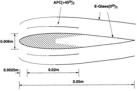
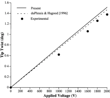
The test case chosen here is an airfoil-shaped cross section with piezoelectric ac-tuators attached at the upper and lower surfaces. This is one of the model beams fabricated and tested by duPlessis and Hagood [11] using AFC. In each AFC pack, the
KI Present VABS % Difference
K 11 8.472 105 8.477 105 -0.1 K12 -1.828 103 -1.794 103 +1.9 K1 3 6.395 102 6.337 102 +0.9 K22 1.299 102 1.278 102 +1.6 K23 4.547 101 4.461 101 -1.9 K33 9.631 101 9.567 101 +0.7 K44 2.075 102 2.070 102 +0.2

![Figure 3-5: Schematic diagram of the complete CH-47D active blade section [28]](https://thumb-eu.123doks.com/thumbv2/123doknet/14722773.570841/55.918.223.664.132.477/figure-schematic-diagram-complete-ch-active-blade-section.webp)

![Table 4.2: Numerical comparison of actuation vector components for airfoil-shaped beam Present duPlessis & Hagood [1996] -0 500 1000 1500 2000 Applied Voltage (V)](https://thumb-eu.123doks.com/thumbv2/123doknet/14722773.570841/64.918.153.798.154.670/numerical-comparison-actuation-components-present-duplessis-applied-voltage.webp)
