HAL Id: hal-01269325
https://hal.archives-ouvertes.fr/hal-01269325
Submitted on 3 Jun 2020HAL is a multi-disciplinary open access L’archive ouverte pluridisciplinaire HAL, est
Transient regime to fluidized chimney within a granular
bed by means of a 2D DEM/LBM modeling
Jeff Ngoma, Pierre Philippe, Stéphane Bonelli, Pablo Cuellar, Jean-Yves
Delenne, Farhang Radjai
To cite this version:
Jeff Ngoma, Pierre Philippe, Stéphane Bonelli, Pablo Cuellar, Jean-Yves Delenne, et al.. Transient regime to fluidized chimney within a granular bed by means of a 2D DEM/LBM modeling. 4. Interna-tional Conference on Particle-based Methods – Fundamentals and Applications, Sep 2015, Barcelone, Spain. 1121 p. �hal-01269325�
IV International Conference on Particle-based Methods – Fundamentals and Applications PARTICLES 2015 E. Oñate, M. Bischoff, D.R.J. Owen, P. Wriggers & T. Zohdi (Eds)
TRANSIENT REGIME TO FLUIDIZED CHIMNEY WITHIN A
GRANULAR BED BY MEANS OF A 2D DEM/LBM MODELING
JEFF NGOMA1,2, PIERRE PHILIPPE1, STEPHANE BONELLI1, PABLO CUÉLLAR1,
JEAN-YVES DELENNE3 AND FRANCK RADJAI4,5
1 OHAX, IRSTEA (French Research Institute of Science and Technology for Environment and
Agriculture), 3275 route de Cézanne CS40061, 13182 Aix-en-Provence, France jeff.ngoma@irstea.fr, pierre.philippe@irstea.fr, stephane.bonelli@irstea.fr, http://irstea.fr/
2 Institut Jean Lamour, CNRS - Université de Lorraine, Parc de Saurupt
CS 50840, 54011 Nancy, France
jeff.ngoma@univ-lorraine.fr, http://ijl.univ-lorraine.fr/
3 UMR IATE, INRA – CIRAD - Montpellier Supagro - Université Montpellier 2
2 place Pierre Viala, 34060 Montpellier, France delenne@supagro.inra.fr, http://umr-iate.cirad.fr/
4 Laboratoire de Mécanique et Génie Civil, CNRS - Université Montpellier 2
Place Eugène Bataillon, 34095 Montpellier, France Franck.Radjai@univ-montp2.fr, http://www.lmgc.univ-montp2.fr/
5 UMI 3466 CNRS – MIT, Department of Civil and Environmental Engineering, MIT, 77
Massachusetts Avenue, Cambridge CA 02139, USA fradjai@mit.edu, http://www. http://cee.mit.edu/ Key words: Granular Materials, DEM, LBM, Fluidization.
Abstract. Beyond a given threshold, an upward fluid flow at constant flowrate, injected through a small size section, is able to generate a fluidization along a vertical chimney over the entire height of a granular assembly. Fluidization is first initiated in the immediate vicinity of the injection hole and then the fluidized zone grows gradually until reaching the upper surface of the granular packing. In this work, we present numerical results on the kinetics of chimney fluidization in an immersed granular bed produced with two-dimensional simulations coupling the Discrete Element and Lattice Boltzmann Methods (DEM-LBM). A parametric study is carried out with 11 different sets of physical parameters and analyzed based on spatio-temporal diagrams. Then a dimensional analysis allows finding general scaling laws for both threshold and growth rate of the fluidized zone by use of two dimensionless numbers, namely Reynolds and Archimedes numbers, while quite simple empirical relationships can also be proposed.
J. Ngoma, P. Philippe, S. Bonelli, P. Cuéllar, J.-Y. Delenne and F. Radjai
1 INTRODUCTION
A fluidized state within a granular bed is reached when the upward force exerted by the flow can balance the buoyant weight of the particles. Fluidization is used extensively in industry for drying, mixing and agglomeration processes with many applications as gasification of biomass, ion exchange processes or high efficiency carbon capture. Some among these industrial processes rely more specifically on a localized state of fluidization as is the case for spouted beds [1] and tapered beds [2] which are generated by means of an upward gas flow injected most often at the neck of a conical container. Contrariwise, channelization, i.e. occurrence of such preferential channels of fluidization, is to be absolutely avoided for other types of fluidized bed applications. In sedimentology, some geologic formations of fluid escape structures by localized fluidization through vertical pipe have been specifically examined [3]. A somehow similar situation is encountered in the context of dike safety, when a seepage flow through the foundation of an embankment is susceptible to generate such a local fluidization, commonly called “sandboil”, and possibly initiate a piping process by backward erosion, which is one of the four basic mechanisms identified for soil particles removal by internal erosion [4].
Here the focus is put more restrictively on the development and growth of a local fluidized state within an immersed granular assembly induced at the bottom of the grain bed by an upward fluid flow passing through a small injection hole. Several previous works have studied specifically this configuration and analysed the formation of a vertical chimney of fluidized soil on the basis of either experiments [5, 6] or numerical simulations coupling Discrete Element Method (DEM) with Lattice Boltzmann Method (LBM) [7]. It should be noted, however, that most efforts have been so far dedicated to the steady state rather than to the transitory development of such fluidized chimney [6]. This transient regime of localized fluidization is therefore specifically under the scope of the present study. For this purpose, a numerical model based on a 2D DEM/LBM coupled approach has been implemented to carry out a systematic analysis of the temporal evolution of the fluidized zone, expanding progressively from the injection hole to the top of the granular layer. As will be detailed below, a critical fluid velocity Uc as well as the growth rate of the fluidized cavity above this threshold can be precisely defined. Using the relevant dimensionless numbers of the problem, a general collapse of the data can be obtained, which permits the proposal of empirical scaling laws both for the critical velocity and for the fluidization growth rate.
The following sections first introduce the numerical approach developed in the present study and then focus specifically on the transient regime to fluidized chimney within an immersed granular bed subject to a localized fluid injection at its base.
2 NUMERICAL METHODS
Many numerical methods are developed to simulate fluid-particles interactions at the micro-scale. The crucial point is the approach taken to couple the particles’ dynamics and the interstitial fluid flow. Here we have chosen to tackle this issue by a simultaneous use of the Discrete Element Method (DEM) and of the Lattice Boltzmann Method (LBM). This choice has the advantage to combine the comparative simplicity of DEM with LBM, one of the most efficient computational methods for fluid dynamics. Both methods as well as the coupling
2.1 DEM modeling of the solid phase
In this study, the Discrete Element Method (DEM) is implemented through the Molecular Dynamics modeling, a numerical method originally developed by Cundall and Strack [8] for rock mechanics applications and which quickly became very popular in many other fields of application dealing with interacting solid particles [9]. The Molecular Dynamics method considers the solid material as discrete particles that interact with each other in areas of mutual contact. The particles are assumed to be rigid with possibly a small overlap at the contact while the interactions are modelled by appropriate and physically based laws depending on this overlap. Then, the particles’ motion can be directly described by Newton’s equations. More details can be found in [10, 11].
2.2 LBM modeling of the fluid phase
A classical D2Q9 scheme is used here for LBM describing the fluid flow within the grains, allowing for an explicit finite differences calculation of Boltzmann equation on a Cartesian lattice grid (2D) and using a discrete set of velocity vectors at each grid node (Q9) [12]. The calculation is related to a probability density function, discretized on the lattice, and computed in two successive steps: collision and advection, both assuming specific rules to ensure mass, momentum and energy conservation provided that Mach number is very low or, equivalently, that fluid velocity remains significantly smaller than the lattice speed. With this condition, the fluid flow follows the incompressible Navier-Stokes equations. Note also that, instead of the classical single relaxation time scheme originally proposed by Bhatnaggar, Gross, and Krook [12], a multiple relaxation time (MRT) is advantageously implemented here, following the generalized formulation by d’Humières [13, 14]. Further details on this method can also be found in [10, 11].
2.3 Solid-fluid coupling
In our modelling, the simple technique proposed by Bouzidi et al. [15] for momentum exchange is implemented to calculate the hydrodynamic forces on each discrete particle and couple this way the fluid and solid phases. This computation is based on a generalized bounce-back condition with a linearly interpolated geometry of the particles boundary inside the fluid lattice. A key parameter for the fluid-solid coupling is the space resolution, i.e. the lattice grid size compared to the minimum particle diameter. It is commonly accepted that a satisfactory result can be obtained with at least 10 grid points per grain diameter, which is the resolution used in the present study for an affordable computational cost. Moreover, as the calculation time is much larger for LBM than DEM, we have used the sub-cycling time integration technique proposed by Feng et al [16] with a number of DEM sub-cycles which is restricted to 2 for each LBM loop, a good compromise to maintain the accuracy of the computed hydrodynamic forces on the solid particles. In order to overcome the fact that a real 2D assembly of discs in contact is an occluded space with a zero permeability value, the LBM calculations are here carried out with a constant reduction of the particles’ radius by a factor of 0.8, which provides a realistic permeability value [17] and roughly accounts for lubrication forces [18].
J. Ngoma, P. Philippe, S. Bonelli, P. Cuéllar, J.-Y. Delenne and F. Radjai
3 TRANSIENT REGIME TO FLUIDIZED CHIMNEY 3.1 Configuration and parameters
Based on the coupled DEM-LBM technique described above, a two-dimensional numerical modeling was carried out to simulate an assembly of grains subjected to a localized fluid injection at its base. Grain sizes have a mean value d and are uniformly distributed from 0.8d to 1.2d. Two different samples have been used with initial height H0 equal respectively to approximately 86 mm and 54 mm while the overall domain dimensions are L = 222 mm in length and H = 160 mm in height. The bottom boundary is a solid wall except for a filtering orifice of width D = 14mm at its center which allows the fluid to be injected upwards at a constant velocity U but remains impassable for the grains. A velocity inlet condition is thus implemented at the injection hole while a periodic condition is set at the top and bottom boundaries of the domain. A no-slip condition is implemented on all other boundaries, considered as solid walls. A sketch of the configuration is shown in Figure 1.
Figure 1: Configuration and boundary conditions of the numerical study.
To reach a fluidized state, the drag forces induced by the interstitial flow must overcome the inter-granular forces within the particles’ sample. In the studied conditions of purely frictional interactions between grains, the internal granular stress is solely related to the buoyant weight of the system. Consequently, the physical parameters of the problem are: the
of the grains g, and finally the gravity g. The control parameter used here is the injected fluid velocity U while the geometry of the system is fixed by the initial height H0, the width of the domain L and the diameter of the injection hole D. In what follows, L and D remain unchanged and, since D is much smaller than L (D/L 0.06), it can be reasonably considered that L plays a minor role.
A parametric study has been carried out using 11 different parameter sets (see Table 1) enabling some of the physical parameters to be significantly varied, namely f, g, g and d. Two different values of the initial height H0 has also been used while the injection diameter D was kept constant (D = 14mm).
Table 1: Sets of parameters
Set number f (m2.s-1) g (kg.m-3) g (m.s-2) d (mm) 1 5.10-5 2500 9.81 2 2 1.10-5 2500 9.81 2 3 5.10-5 2500 1 2 4 1.10-5 1500 9.81 2 5 5.10-5 1500 9.81 2 6 5.10-5 2500 1 2 7 5.10-6 2500 9.81 2 8 5.10-6 1500 9.81 2 9 2.10-6 2500 9.81 2 10 2.10-6 1500 9.81 2 11 5.10-5 2500 9.81 4
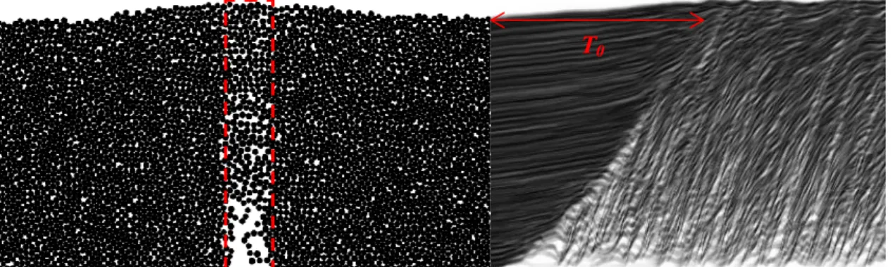
For all parameter sets, the analysis of the transitory evolution to final fluidized chimney is performed using space-time diagrams constructed at the injection from the different sequences obtained for each successive fluid velocity U imposed at the injection hole (Figure 2). From these diagrams, it is then possible to determine quite accurately the time T0 needed for the fluidized zone to expand upwards to a height equal to H0.
Figure 2: Typical space-time diagram used to determine the duration T0 of the transient regime and calculated in the rectangular area (in dotted line) located above the injection hole.
J. Ngoma, P. Philippe, S. Bonelli, P. Cuéllar, J.-Y. Delenne and F. Radjai
3.2 Chimney expansion time and growth rate
Plotting the chimney expansion time T0 as a function of the injection velocity U, a divergence is observed when U tends to a threshold value Uc which can be accurately determined by use of the following power law adjustment of the curve:
T0(U) = 0(U/Uc – 1)- (1)
where 0 is a constant equal to T0(U = 2Uc) and is the opposite of the exponent.
The value of can be satisfactorily chosen within the range 0.5 < < 0.7 with a small but still significant impact on the threshold velocity Uc. Of probably greater interest is V0 = H0/T0, the characteristic growth rate which quantifies the velocity at which the fluidized zone expands upwards. Here again, as shown in Figure 3, a power law can be used with the opposite exponent :
V0(U) = 0(U/Uc – 1) (2)
where 0 is a constant equal to V0(U = 2Uc) .
Figure 3: Characteristic growth rate V0 of the fluidized zone versus fluid injection velocity U for H0 = 86 mm. The lines are power law functions given by Equation (2) with = 0.6.
It can be noted that in the present study has been arbitrarily fixed equal to 0.6 and, depending on the parameters in Table 1, the values obtained for Uc vary on several orders of magnitude as can be noticed in Figure 3.
3.3 Scaling laws
Accounting for buoyancy, the only relevant physical quantities are the fluid kinematic viscosity , the fluid injection velocity U, the grain diameter d, and the resultant buoyant
gravity g* = g(g /f -1). From these magnitudes, two dimensionless numbers can be formed, namely the Reynolds number Re = Ud/f and the Archimedes number Ar = g*d3/f 2. And thus, the critical Reynolds number Rec = Uc d/f should consequently be simply dependent on
Ar. As shown in Figure 4, such a relationship is indeed reasonably well obtained for all values
corresponding to the 11 different sets of parameters and a very simple empirical power law relation can be proposed:
Rec Ar3/4 (3)
Therefore, the dependencies on the geometrical parameters H0 and D are completely taken into account by the proportionality factor in Equation (3).
Figure 4: The critical Reynolds number Rec plotted as a function of Archimedes number Ar for H0 = 86 mm. The line corresponds to Equation (3) with a proportionality factor equal to 0.1.
Such a dimensional analysis can be extended beyond the critical value for chimney fluidization to account more broadly for the transient behavior obtained once this threshold is exceeded, i.e. for U > Uc. For this purpose, we now use the general expression of the Reynolds number, Re=Ud/f, while the characteristic growth rate V0 is also made dimensionless by introducing a new Reynolds numbers Re0 defined as follows:
Re0 = V0d/f (4)
Finally, to get rid of the additional dependencies due to the geometry of the system (mainly through the initial height H0), Re and Re0 are both divided by the critical Reynolds number Rec. This way, as shown in Figure 5, a global collapse of all the data is obtained, confirming the previous analysis. Moreover, following Equation (2), a general empirical scaling law can now be proposed in the form:
J. Ngoma, P. Philippe, S. Bonelli, P. Cuéllar, J.-Y. Delenne and F. Radjai
Note that the proportionality factors obtained for the two values of H0 used in this study are indeed rather close although slightly different, equal to 0.75 and 0.95 respectively for H0 = 86 mm and H0 = 54 mm.
Figure 5: The ratio Re0/Rec plotted versus Re/Rec-1 for H0 = 86 mm. The line stands for Equation (5) with a proportionality factor being equal to 0.75.
4 CONCLUSION
A 2D coupled DEM-LBM model has been implemented to produce a realistic representation of fluid-grains interactions and dynamics. This model has been successfully applied to study the particular phenomenon of development of a fluidized chimney within an immersed granular bed from a small fluid injection hole at the base of a grain assembly. Focusing specifically on the transient regime leading to a steady chimney, a parametric analysis has been undertaken with 11 different sets of the main physical parameters involved in the problem. The first outcome of this study shows that the critical fluid velocity Uc needed for such a chimney fluidization can be clearly interpreted in terms of dimensionless numbers. The corresponding critical Reynolds Rec = Ucd/f is indeed simply a function of the Archimedes number Ar = g(g /f -1) d3/f 2 which is fairly compatible with an empirical power law relation: Rec Ar3/4.
In addition, the characteristic growth rate V0, i.e. the upward expansion rate of the fluidized zone, can also be predicted from our dimensional analysis provided that additional Reynolds numbers are formed using the different velocities of the system: U, Uc and V0. This way, it is possible to obtain a general collapse of all data from the different parameter sets, allowing the proposal of a very simple empirical law: Re0 / Rec (Re/Rec – 1)3/5.
REFERENCES
[1] Mathur, K. and Epstein, N. Spouted Beds. Academic Press, New-York, USA (1974). [2] Peng, Y. and Fang, L.T. Hydrodynamic characteristics of fluidization in liquid-solid
tapered beds. Chemical Engineering Science (1997) 52(14):2277-2290.
[3] Nichols, R.J., Sparks, R.S.J. and Wilson, C.J.N. Experimental studies of the fluidization of layered sediments ant the formation of fluid escape structures. Sedimentology (1994) 41(2):233-253.
[4] Bonelli, S. (Editor). Erosion in Geomechanics Applied to Dams and Levees. Wiley-ISTE (2013).
[5] Zoueshtiagh, F. and Merlen, A. Effect of a vertically flowing water jet underneath a granular bed. Physical Review E (2007) 75(5):053613.
[6] Philippe, P. and Badiane, M. Localized fluidization in a granular medium. Physical
Review E (2013) 87(4):042206.
[7] Cui, X., Li, H., Chan, A. and Chapman, D. A. A 2D DEM-LBM study on soil behaviour due to locally injected fluid. Particuology (2012) 10:242-252.
[8] Cundall, P.A. and Strack, O.D.L. A discrete numerical model for granular assemblies.
Géotechnique (1979) 29:47-65.
[9] Radjai, F. and Dubois, F. (Editors). Discrete-element Modeling of Granular Materials. Wiley-ISTE (2011).
[10] Ngoma, J., Philippe, P., Bonelli, S., Delenne J.-Y. and Radjai, F. Interaction between two localized fluidization cavities in granular media: Experiments and numerical simulation. In Geomechanics From Micro to Macro, Soga, K., Kumar, K., Biscontin, G. and Kuo, M. (Editors), CRC Press/Balkema, Taylor & Francis Group, London, UK (2015).
[11] Ngoma, J. Etude numérique et expérimentale de la déstabilisation des milieux
granulaires immergés par fluidisation (2015), PhD thesis, Aix-Marseille University,
France.
[12] Sukop, M. C. and Thorne, D. T. Lattice Boltzmann Modeling. An Introduction for
Geoscientists and Engineers. Springer, Berlin (2005).
[13] d’Humières, D., Ginzburg, I., Krafczyk, M., Lallemand, P. and Luo, L.-S. Multiple-relaxation-time lattice Boltzmann models in three dimensions. Philosophical
Transactions of the Royal Society London A (2002) 360:437-451.
[14] Yu, D., Mei, R., Luo, L.-S. and Shyy, W. Viscous flow computations with the method of lattice Boltzmann equation. Progress in Aerospace Sciences (2003) 39:329–367.
[15]Bouzidi,M., Firdaouss, M. and Lallemand, P. Momentum transfer of a Boltzmann-lattice fluid with boundaries. Physics of Fluids (2001) 13(11):3452.
[16] Feng, Y.T., Han, K. and Owen, D.R.J. Coupled lattice Boltzmann method and discrete element modelling of particle transport in turbulent fluid flows: Computational issues.
International Journal for Numerical Methods Engineering (2007) 72:1111–1134.
[17] Boutt, D.F., Cook, B.K. and Williams, J. R. A coupled fluid–solid model for problems in geomechanics: Application to sand production. International Journal for Numerical and
Analytical Methods in Geomechanics (2011) 35:997–1018.
[18] Mutabaruka, P., Delenne, J.-Y., Soga, K. and Radjai, F. Initiation of immersed granular avalanches. Physical Review E (2014) 89(5):052203.