HAL Id: cea-02338723
https://hal-cea.archives-ouvertes.fr/cea-02338723
Submitted on 24 Feb 2020
HAL is a multi-disciplinary open access
archive for the deposit and dissemination of
sci-entific research documents, whether they are
pub-lished or not. The documents may come from
teaching and research institutions in France or
abroad, or from public or private research centers.
L’archive ouverte pluridisciplinaire HAL, est
destinée au dépôt et à la diffusion de documents
scientifiques de niveau recherche, publiés ou non,
émanant des établissements d’enseignement et de
recherche français ou étrangers, des laboratoires
publics ou privés.
Performance evaluation of several well-known and new
scintillators for MeV X-ray imaging
D. Tisseur, N. Estre, L. Tamagno, C. Eleon, D. Eck, E. Payan, N. Cherepy
To cite this version:
D. Tisseur, N. Estre, L. Tamagno, C. Eleon, D. Eck, et al.. Performance evaluation of several
well-known and new scintillators for MeV X-ray imaging. 2018 IEEE Nuclear Science Symposium and
Medical Imaging Conference, Nov 2018, Sydney, Australia. pp.1-3, �10.1109/NSSMIC.2018.8824663�.
�cea-02338723�
Performance evaluation of several well-known and
new scintillators for MeV X-ray imaging
David Tisseur, Nicolas Estre, Léonie Tamagno, Cyrille Eleon, Daniel Eck, Emmanuel Payan, Nerine Cherepy
Abstract– Digital X-ray imaging systems for MeV range
photon beams are based on a combination of a scintillator screen and either a camera or an amorphous silicon array. To limit dose rate on electronics and enhance imaging device lifetime, the scintillator screen is mirror-coupled to the camera. Performances of such devices are a compromise between exposure time and spatial resolution. These technical characteristics are especially scintillator dependent. In this paper, we present a performance evaluation of six different scintillators with a 9 MeV Bremsstrahlung X-ray source. The tested scintillators are composed of one micro-structured CsI(Tl) scintillator, two phosphor (GOS) screens and three transparent scintillators. These scintillators present a wide range of density, thickness and conversion efficiency. Each scintillator’s performance is assessed based on the combination of light output (ADU number) and modulation transfer function (spatial resolution) obtained. The results are helpful to guide design and engineering of high energy imaging devices adapted to specific requirements.
Index Terms — Radioscopy; High-Energy X-ray; Linac;
Scintillator; X-ray imaging
I. INTRODUCTION
Many papers in the literature report performance of various scintillators for digital imaging in the range of classical X-ray tube energy [1][2][3] or synchrotron applications [4][5]. Concerning imaging in MeV range for non-destructive testing (NDT), literature is less abundant [6]. In this paper, we present a study of scintillator imaging performance for a 9 MeV linear accelerator beam. We selected well-known phosphor screens, micro-structured, single crystal and transparent ceramic scintillators. These tests are intended to help define the desired scintillator properties, geometry and optical configuration to optimize our 9 MeV radiography system.
II. SCINTILLATORS PERFORMANCE EVALUATION SET-UP
Tests were performed with a 9-MeV Linear accelerator [8] in a cell named KROTOS at CEA Cadarache [9]. The scintillators evaluated were: two GOS (Gd2O2S:Tb) phosphor
powder screens (Medex from AST, Lanex Fast Back from Kodak) one micro-structured CsI(Tl) scintillator provided by Hamamatsu, and three transparent scintillators - BGO (Bi4Ge3O12) from Saint Gobain, LYSO (Lu1.9Y0.1SiO5, Cerium
content: 0.5mol%) from JT Crystal Technology and GLO (Gd0.3Lu1.6Eu0.1O3) from Lawrence Livermore National
D. Tisseur, N. Estre, L. Tamagno, C. Eleon, D. Eck, E. Payan, are with CEA, DEN, Cadarache, Nuclear Measurement Laboratory, F-13108 Saint-Paul-lez-Durance, France. N. Cherepy is with the Lawrence Livermore National Laboratory, L168, Livermore, CA, 94550, USA.
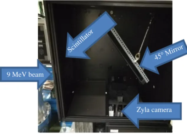
Laboratory [10]. These scintillators present a wide range of density, thickness and conversion efficiency. Tables I and II summarize the physical and optical properties of the scintillators studied. Each scintillator screen is imaged by a low noise S-CMOS 2160x2560 pixels (ANDOR Zyla 5.5) camera through a 45° tilted mirror in a light-tight box. A lead block prevents damage to the camera (see Fig. 1). The average detector dose rate was 0.92 mGy/s.
Fig. 1. Experimental setup.
The light output measured for each scintillator results from its stopping power (primarily determined by density in the MeV pair-production regime), luminosity (a constant for each scintillator), and optical configuration (optical scattering,
9 MeV beam
Zyla camera
TABLEI
SCINTILLATOR PHYSICAL AND OPTICAL CONFIGURATION USED
Scintillator Density (g/cm3)
Thickness Configuration Medex, GOS 7.32 780 µm On 2 mm brass plate Lanex, GOS 7.32 290 µm See [11]
CsI 4.51 2 mm On 2 mm Cu plate BGO 7.13 3 mm
Blackened surfaces other than exit surface LYSO 7.25 25 mm
GLO 9.10 1.58 mm TABLEII
SURVEY OF CHARACTERISTICS OF SELECTED SCINTILLATORS
Scintillator name Surface density in mg/cm2 Light yield (photons/MeV) Optical index Medex 347 65000
Lanex Fast Back 134 65000 CsI 902 54000
BGO 899 8000-10000 2.15 LYSO 18500 30000 1.82 GLO 1438 55000 1.89
reflective or black backing). Light output was measured via mean ADU number in a 50 pixels x 50 pixels region of interest of the image with an exposure time of 1 s. To avoid photonic noise, 10 images are averaged. A 5 cm x 5 cm x 10 cm copper block placed in front of the scintillator was used for modulation transfer function (MTF) evaluation with classical edge method. Edge spread function (ESF) was fitted with a combination of 2 Gauss error functions. Line spread function was obtained from the analytical derivative of the ESF. Then the MTF was given by analytical LSF Fourier transform. Considering the distance from the linear accelerator to the detector box of 3125 mm, source size blur was considered to be negligible.
III. RESULTS AND ANALYSIS
In order to compare the six different scintillators, LYSO was selected as the reference screen (best known light yield with ±10% uncertainty), and all as-measured light output values were normalized to LYSO, but are not normalized for thickness, density or any other physical property. Each MTF curve for each scintillator and optical MTF has been evaluated (see Fig. 2). In order to be independent of the optical MTF, scintillators MTF have been corrected from optical MTF. Spatial resolution is computed using [12] definition:
𝑆𝑝𝑎𝑡𝑖𝑎𝑙 𝑟𝑒𝑠𝑜𝑙𝑢𝑡𝑖𝑜𝑛 = 1
2 ∗ 𝑀𝑇𝐹20%
Fig. 2. MTF corresponding to the six scintillators and optical part. Table III summarizes the results obtained. The highest light output was obtained with CsI. Thanks to CsI micro-columnar structure, spatial resolution (994 µm) is better than Medex (1259 µm) and LYSO (1037 µm). With the highest thickness (25 mm), LYSO scintillator has a light output comparable to Medex with a little better spatial resolution (1037 µm). The best spatial resolution is achieved with GLO (401 µm). The 1.58 mm thick GLO scintillator was 2 times brighter than the 3 mm thick BGO crystal, both prepared with black backing to eliminate scattered and back-reflected scintillation light (see Fig. 3).
Fig. 3. Measured scintillator light output vs spatial resolution To analyze our results on scintillator performance, we have performed MCNP6 Monte Carlo simulation [13] and compared the measurements to the expected results for transparent scintillators (BGO, GLO). Simulations are in accordance with measurement excepted for GLO. Work is under progress to understand this result.
IV. CONCLUSION AND PERSPECTIVES
This study measured imaging performance with a 9 MeV Bremsstrahlung source of a wide range of scintillators including the well-known BGO, CsI GOS and newer scintillators, LYSO, GLO. The completed final paper will present more details particularly in experimental data and simulation analysis.
V. REFERENCES
[1] S. Vedantham et al., Full Breast Digital Mammographic Imaging with
an Amorphous Silicon-based Flat Panel Detector: Physical Characteristics of a Clinical Prototype, Med. Phys. 27: 558-567, 2000.
[2] K.W. Jee, L.E. Antonuk, Y. El-Mohri, Q. Zhao, System performance of
a prototype flat-panel imager operated under mammographic conditions, Med Phys. Jul;30(7):1874-90, 2003.
[3] M. Nikl, Scintillation detectors for X-rays, Meas. Sci. Technol. 17 R37, 2006
[4] A. Koch, Lens coupled scintillating screen-CCD X-ray area detector
with a high detective quantum efficiency, Nucl. Instrum. Meth. A
348 654, 1994
[5] H. Xie, G. Du, B. Deng, R. Chen, T. Xiao, Study of Scintillator thickness
optimization of lens-coupled X-ray imaging detectors, Journal of
instrumentation, vol. 11, num. 03, 2016
[6] S. Baker et al., Scintillator efficiency study with MeV xrays, Proc. SPIE, vol. 9213, pp. 92130, 2014.
[7] D. Partouche-Sebban et al., Multi-MeV Flash Radiography in Shock
Physics Experiments: Specific Assemblages of Monolithic Scintillating Crystals for Use in CCD-Based Imagers, January 2010, X-Ray Optics
and Instrumentation 2010(3), DOI 10.1155/2010/156984
[8] N. Estre et al., High-energy X-ray imaging applied to nondestructive
characterization of large nuclear waste drums, IEEE Trans. Nucl. Sci.,
vol. 62, no. 6, (2015) p. 3104
[9] N. Estre, L. Berge, E. Payan, Fast megavoltage X-rays radioscopy, Conference: 2016 IEEE NSS/MIC/RTSD,October 2016
[10] N.J. Cherepy et al., Transparent Ceramic Scintillators for Gamma
Spectroscopy and MeV Imaging, SPIE Optical Engineering+
Applications, 95930P-95930P-7 (2015)
[11] ©Eastman Kodak Company, 2005, Film-screen systems and KODAK
LANEX screen, available at http://www.ndt-service.de/wp-content/uploads/2012/02/Lanex-screens.pdf
[12] ISO 16371-1, Industrial computed radiography with storage phosphor
imaging plates — Part 1: Classification of systems
[13] J.T. Goorley, et al., “Initial MCNP6 Release Overview – MCNP6
Version 1.0”, LANL Report, LA-UR-13-22934 (2013).
0 200 400 600 800 1000 1200 1400 0 0,5 1 1,5 2 Spat ial re sol ut ion in m icr on Sensitivity
Spatial resolution vs sensitivity
Medex Lanex LYSO CsI GLO BGO TABLEIII
SCINTILLATOR PERFORMANCE SUMMARY
Scintillator name Measured light output Spatial resolution in µm Medex 0.96 1259 Lanex 0.12 746 CsI 1.52 994 BGO 0.12 625 LYSO 1 1037 GLO 0.21 401