HAL Id: in2p3-00867502
http://hal.in2p3.fr/in2p3-00867502
Submitted on 4 Mar 2014
HAL is a multi-disciplinary open access
archive for the deposit and dissemination of
sci-entific research documents, whether they are
pub-lished or not. The documents may come from
teaching and research institutions in France or
abroad, or from public or private research centers.
L’archive ouverte pluridisciplinaire HAL, est
destinée au dépôt et à la diffusion de documents
scientifiques de niveau recherche, publiés ou non,
émanant des établissements d’enseignement et de
recherche français ou étrangers, des laboratoires
publics ou privés.
R. Ferdinand, P.E. Bernaudin, M. Di Giacomo, P. Bosland, G. Olry, Y.
Gomez Martinez
To cite this version:
R. Ferdinand, P.E. Bernaudin, M. Di Giacomo, P. Bosland, G. Olry, et al.. Status and challenges
of Spiral2 SRF linac. 16th International Conference on RF Superconductivity (SRF2013), Sep 2013,
Paris, France. pp.11-17. �in2p3-00867502�
STATUS AND CHALLENGES OF SPIRAL2 SRF LINAC
R. Ferdinand, P-E. Bernaudin, M. Di Giacomo GANIL/SPIRAL2, Caen, France
P. Bosland, CEA/Irfu, Saclay, France
G. Olry, IPN Orsay, UMR 8608 CNRS/IN2P3 - Université Paris Sud, France
Y. Gómez Martínez, UJF / CNRS-IN2P3 / INPG, LPSC, Grenoble, France
Abstract
GANIL is significantly extending its facility with the new SPIRAL2 project. It is based on a multi-beam Superconducting Linac Driver delivering 5 mA deuterons up to 40 MeV and 1 mA heavy ions up to 14.5 MeV/u.
SPIRAL2 construction is staged in two phases. SPIRAL2 phase 1 includes the superconducting accelerator driver and two research rooms, NFS and S3. In NFS (Neutrons For Science), the accelerated protons and deuterons will generate extremely intense neutron beams for fundamental physics experiments and numerous applications. SPIRAL2 will also accelerate stable heavy ion beams of very high intensity. S3
, the
Super Separator Spectrometer is dedicated to heavy and super-heavy nuclei studies using theses ions beams. SPIRAL2 phase 2 includes the RIB production building, the links to the existing GANIL complex and the future DESIR experimental hall.
The Superconducting Linac incorporates many innovative developments on Quarter-Wave resonators and their associated cryogenic and RF systems in order to fulfill the broad beam demands of the physics. The installation of the SPIRAL2 accelerator at GANIL has started. Status of the Spiral 2 SRF linac is presented, with a highlight of the various SRF challenges met by this project and how/what solutions were chosen.
INTRODUCTION
The GANIL facility [1] (Caen, France) is one of the major Rare (or Radioactive) Ion Beam (RIB) and stable-ion beam facilities for nuclear physics, astrophysics and interdisciplinary research in Europe. From the very beginning of the SPIRAL1 project, an upgrade – SPIRAL2 – was foreseen to increase both the range and the mass of exotic nuclei produced by SPIRAL1 [2, 3]. In the recent years, RIBs have been recognized by the international scientific community as one of the important path for the development of fundamental nuclear physics and astrophysics, as well as in applications of nuclear science.
As an important step between the existing and the next-generation facilities (EURISOL), SPIRAL2 is a facility which meets the criteria of European dimension in terms of physics potential, site and size of the investment as it was recognized in the ESFRI (European Strategy Forum on Research Infrastructures) roadmap.
The SPIRAL2 facility should extend the GANIL
possibilities to heavier radioactive beams, and/or with much higher intensities [4]: it will provide intense beams of neutron-rich exotic nuclei (106–1011pps in the mass
range 60 to 140), created by the ISOL production method. The extracted exotic beam will be used either in a new low energy experimental area called DESIR, or accelerated by the existing SPIRAL cyclotron (CIME). The S3 exotic production can also be analyzed in the DESIR extension.
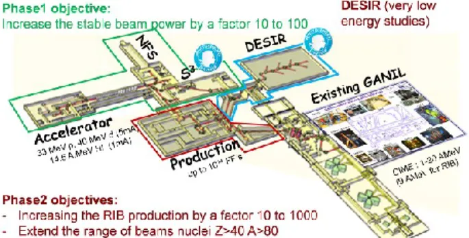
The project has already been described in many documents e.g. [3]. It is built in two phases. The first one includes the linac building, the linac experimental halls (AEL) and the accelerator process (green part of Figure 1). The AEL include the Neutrons For Science (NFS) hall and the Super Separator Spectrometer (S3) hall. Phase two
includes the whole RIBs production equipments and infrastructure, starting from the HEBT to the production building, the production and connections to the existing GANIL facility for post acceleration. Recent decisions were taken to favor the start of physics as soon as possible. The phase 2 construction strategy is modified to anticipate the DESIR facility construction, while the production building will come later on. Development, studies and tests will continue in the meanwhile with the production equipments.
Both S3 and DESIR were recognized as major research
equipments by the French government and received an EQUIPEX funding.
Figure 1: Existing GANIL and SPIRAL2 extension. The accelerator construction is already well advanced, a large list of components being already delivered and tested [5, 6]. It is presently being installed in the building with the objective of obtaining the first source beams by mid 2014. c○ 2013 by the respecti v e authors
Cryomodules are being processed in CEA Saclay and IPN Orsay, inter-cryomodule "warm" sections in GANIL. While installation of the accelerators components is going on in the new SPIRAL2 building in Caen, installation of the cryomodules will begin during the first quarter of 2014. The latest results of the cryomodules tests as well as the installation strategy are depicted in this paper.
SUPERCONDUCTING LINAC
Beam Requirements
The layout (Figure 2) of the SPIRAL2 driver accelerator [7] takes into account the wide variety of physics demands. It shall be able to accelerate high-intensity beams of protons, deuterons, ions with q/A>1/3, and optionally ions with q/A>1/6 (Table 1). Our biggest challenge is to manage this variety of beams, a quite high beam power (200kW, CW) and the deuteron beam (safety issues). This was the main reason for the multi small cryostat design of the superconducting (SC) linac.
Table 1: Beam specifications
Particles H+ 3He2+ D+ ions ions
Q/A 1 3/2 1/2 1/3 1/6
Max. I (mA) 5 5 5 1 1
Min. energy (MeV/A) 0.75 0.75 0.75 0.75 0.75
Max energy (MeV/A) 33 24 20 15 9
Max. beam power (kW) 165 180 200 45 54
Linac General Description
The LINAC accelerator is based on superconducting, independently-phased resonators. In order to allow the broad required ranges of particles, intensities and energies, it is composed of 2 families of short cryomodules developed by the CEA/IRFU and IN2P3/IPNO teams [8]. The first family is composed of 12 quarter-wave resonators (QWR) with =0.07 (one
cavity/cryomodule), and the second family of 14 QWR at =0.12 (two cavities/cryomodule) (see Figure 3). The
maximum gradient in operation of the QWRs is
Eacc = Vacc/βλ = 6.5MV/m. The transverse focusing is
ensured by means of warm quadrupole doublets located between each cryomodule, in so-called “warm sections” also equipped with beam diagnostic and vacuum pumps.
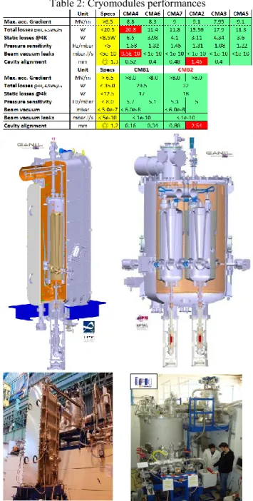
All cavities, six cryomodules type A and one cryomodule type B have been validated (see Table 2). The last cryomodules are expected to be ready by mid 2014.
Developed by IN2P3/LPSC (Grenoble), the RF power couplers shall provide up to 12 kW CW beam loading power to each cavity [9, 10]. Both cryomodules use the
same power coupler with two different external conductor lengths, in order to provide two different coupling factors. Couplers have been validated up to 40kW CW in traveling wave. Their conditioning up to 20 kW CW in standing wave (open circuit) is now shorter than one hour. The last coupler should be prepared by the end of 2013.
Table 2: Cryomodules performances
Figure 3: The SPIRAL2 superconducting cryomodules (left: =0.07 – 1 cavity, right: =0.12 – 2 cavities).
Figure 2: Accelerator scheme.
c○ 2013 by the respecti v e authors
5, 10 and 19 kW solid-state amplifiers will be used to power the linac cavities. Manufacturing is in progress and first units were tested at the GANIL site in 2012.
Various challenges had to be taken into account for the design of this SRF linac. The SC cavities have to provide 6.5 MV/m in cryomodule operation, which is very demanding. The separate vacuum is a consequence of this demand. The compactness of the design is challenging, with short 300-4 K transitions, lots of potential pollution sources and small helium buffer reserve. The high power couplers, working in CW mode, are not common.
CRYOMODULES
In the past, the main difficulties of the cryomodules were related to pollution problems and are explained in details in [8]. Many cryomodules showed strong field emission due to dust pollution, and optimization of the preparation procedures of both cryomodules and power couplers allowed us to solve the problem.
Cryomodule A Status
The designs of the cavity and cryomodules A (CMA) have been described in several conferences [11]. The next paragraphs will describe the recent key points that ensure today's success.
The CMA are small cryomodules housing one single quarter wave resonator at =0.07. As a consequence, it was not possible to include a classical helium buffer, and the volume of helium is quite small. In order to ease the phase separation, porous metallic plates have been introduced on top of the cavities.
After the vertical cryostat test, the cavities are stored under static vacuum, sometimes for months. At the time of the cryomodule assembly in the clean room, and due to the presence of an indium seal between the removable bottom flange and the cavity, they are slowly brought to atmospheric pressure with filtered nitrogen. No HPR is provided before installation inside the cryomodule, as it is usually recommended at this point. Despite this choice, the preparation and RF conditioning run smoothly, as already 8 of the 12 CMA have been assembled and 6 have been tested with success (Figure 4). No cryomodule failed the qualification test since the above procedure has been optimized. The time optimization of the assembly process leads us to set up pairs of cryomodules simultaneously in clean room. At the time of this paper, all possible assemblies have been made, and we are waiting for the clean room availability.
One of the peculiar difficulties is the result of the strong coupling required by the various beams. The antenna tip protrudes inside the cavity resulting in a high electric field (12 MV/m) similar to the one in the accelerating gap area (around 37MV/m). Therefore careful RF conditioning methods are required once the coupler is installed in the cryomodule. The coupler is first conditioned at room temperature at low level in pulsed mode, then in CW mode from 0 to 10 kW. The same procedure is repeated
once the cryomodule has been cooled down at 4 K. In both cases, the cavity is detuned.
Figure 4: CMA ready for delivery.
Then the cavity is tuned and the RF conditioning of the cavity is performed up to 4 MV/m in CW mode. Above this level the RX emissions are too high and lead to quenches, and the cryogenic system is unstable because of a high consumption. Then a kind of High Peak Power Processing (HPPP) is started, switching the conditioning in pulse mode at 50 Hz. Duty cycle is limited to level accepted by the cryogenics and RF power is progressively increased as high as possible to ignite the electronic emission sites. At the end of the RF conditioning cycle, the cavity is well above the required gradient level (around 10 MV/m, typical final duty cycles are around 20-30%). Clear evidence of antenna processing is observed. At nominal gradient (6.5 MV/m) nevertheless, field emission is negligible and the cavity shows performances similar to those measured in vertical cryostat. The cryomodule RF conditioning lasts from typically a few hours and up to almost 6 days in the worst case (one cryomodule).
The cavities being stiff, very little microphonics have been observed, which eases the RF test. It is even possible to run in open loop at the nominal field with helium fluctuation in the order of ±10 mbar.
CMAs exhibit very low static losses, which are very close to the design values.
Cryomodule B Status
The cryomodule B (CMB) was describe in many publications [12, 13, 14]. Each of the cryomodules contains two QWR of =0.12. Like the low beta cavities, the cavity preparation includes “classical” BCP and HPR. The main difference between the two families is related to the absence of removable bottom flange.
All B cavities have been baked at 120 K for 48 hours. It was shown that this baking improves the cryogenic losses by a factor ~2 at the design accelerating gradient (6.5 MV/m). (No similar improvement could be obtained with low beta cavities.)
All cavities were qualified twice in vertical cryostat, once without and once with the cold tuning plunger in right position.
The various tests showed reliable and stable cryogenics, c○2013
by the respecti v e authors
allowing fast cool-down necessary not only to avoid the "Q-disease" but also to ensure that the Amuneal™ magnetic shield is fully efficient, and therefore cooled down before the cavity transition.
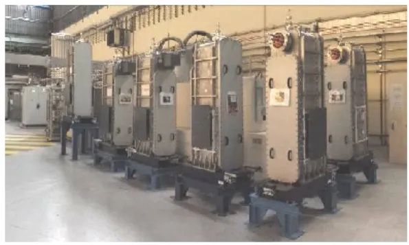
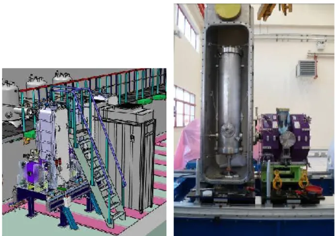
Two cryomodules were validated with respect to RF, vacuum and cryogenic loss requirements; one (CMB2 in Table 2) was unfortunately out of tolerances for one cavity not properly aligned. The second one (CMB1) has been successfully tested. It has already been delivered to GANIL, waiting for the tunnel availability (Figure 5 in the storage area).
During the qualification procedures of the CMB, some difficulties were encountered with the cold tuning system. First, quenches possibly localized around the plunger were eliminated by BCP treatment of all plungers, followed by a qualification of every cavity equipped with its own tuning plunger in vertical cryostat. Secondly, the tuning systems showed a strong mechanical hysteresis leading to a "negative" backlash. This problem is fully described in this conference [15]. It was solved by careful control of the plunger displacement avoiding any swing motion. This innovative tuning system is now fully performing, and has many advantages in the case of such rigid cavities.
Figure 5: The first cryomodule in GANIL, ready for installation in the linac tunnel.
The alignment system is an easy, cheap and effective system allowing cavity positioning both at cold and warm temperatures. The cavity alignment is accessible from outside the cryomodule, giving us possible knobs when will finally come the time of the tunnel installation. The alignment rods of the cavities are not pre-loaded, but are only kept in place at 4.5 K.
Pressure sensitivity is a very important parameter in operation. It was measured around 5 Hz/mbar thanks to the niobium thickness (4.2mm).
The cryomodules are now in a routine assembly process. We expect the delivery at GANIL of one cryomodule every two months, the last one around summer 2014.
COUPLERS
We have 26 couplers along the linac, 12 for the 0.07 beta cavities and 14 for the 0.12 beta cavities. Up to now 20 couplers have been prepared at LPSC Grenoble, 9 for the low beta cavities and 11 for the high beta cavities. 11 couplers have been assembled and tested in the various cryomodules with results in or better than specifications.
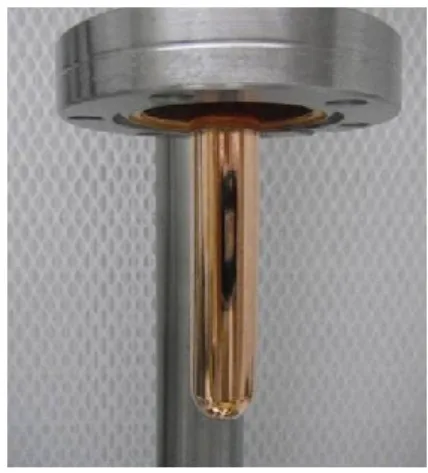
Figure 6: Electropolished antenna tip.
As already mentioned, the electric field on the antenna tip is quite high (10.5MV/m in CMB and 12 MV/m in CMA). Therefore cleanliness and preparation requirements for the power couplers are similar to those of the superconducting cavities [10]. Antenna tips are now electropolished (Figure 6), and the number and size of particles is checked at every step of the preparation in the clean room, as it is for every component installed inside the beam vacuum of the cryomodules. The required time for the RF conditioning step, done first on the LPSC test stand before sending the coupler to the cryomodule teams, improved a lot with the new preparation steps. Couplers are now commonly RF conditioned in about 1 hour.
The couplers are now cleaned, dry, assembled, RF tested and transported in vertical position, upside down. They are reversed only at the time of the cryomodule assembly.
The goal is to finish the preparation of all the couplers by Christmas 2013.
RF AMPLIFIERS
Each cavity is driven by a solid state amplifier (SSA) [16], protected by an external circulator as shown in Figure 7.
Figure 7: Power chain of the SC linac cavities. The circulator sits as close as possible to the cavity, to reduce stress and losses in the transmission (T) lines. Due
c○ 2013 by the respecti v e authors
to the building layout and to room availability in the accelerator hall, we have a first T-line section from the amplifier to the circulator, L1, standing a reduced mismatching (4% of reflected power or VSWR<1.5) and a second section, L2, with high VSWR.
The base module is equipped with four, 1 kW transistors (BLF578, NXP) combined by in-phase, isolated combiners (Wilkinson). Two modules are combined again with the same kind of device to obtain 5 kW units. Two or four of these sets are coupled using star, non-isolated combiners to obtain the 10 and 19 kW units. At the end, we get four kinds of SSA, all based on the same 2.5 kW module for maintenance purpose.
Figure 8: First cabinets of solid state amplifiers being tested at GANIL on the variable VSWR test bench.
First 2.5 kW, 5 kW, 10 kW and 19 kW units have been commissioned and fit the project requirement: 4% of reflected power, at any phase and at nominal output power (Figure 8).
WARM FOCUSING SECTIONS
The transverse focusing is made by a doublet of warm quadrupoles sitting in-between cryomodules. The warm section design required a difficult consensus to allow the insertion of a number of elements in the very short available space: two quadrupoles, two steering magnets (one horizontal and one vertical), one BPM for beam position, information on beam size (transverse matching) and phase measurements, one longitudinal beam extension monitor, and pumping and vacuum diagnostics system.
Figure 9: warm sections during clean room assembly (left) and on alignment bench (right).
Figure 10: left - Laminar air flow in-between cryomodules in the linac tunnel, right – test of the assembly between a warm section and a CMA in Saclay.
Assembly of all components connected to beam vacuum is performed in an ISO5 clean room in Saclay by the GANIL team.
The most critical step of the linac installation is the connection between warm sections and cryomodules. Cavities are being kept under static vacuum (vacuum level being checked regularly and kept below a 0.1 mbar threshold). The warm sections are kept at atmospheric pressure, but dust-free sealed. Connection will be performed under a mobile, ISO5 laminar air flow, specially designed to fit inside the very constraint space between two cryomodules and under the valves box support platform (Figure 10). Meticulous cleaning and particle counts will ensure that the environment is clean enough to perform the connection operation, which is itself very delicate: a Helicoflex™ seal shall be inserted and sealed in a very tight space. This connection has been tested at CEA Saclay with an empty cryomodule.
GANIL INSTALLATION
Transportation
Cryomodule transportation from Saclay and Orsay to GANIL is made by truck (250 km by road). It has been identified as being a critical operation, potentially destructive for the coupler. Therefore one transportation test has been organized in March 2013. One fully performing low cryomodule was moved from Saclay to GANIL, unloaded in GANIL, then loaded again on the truck and transported back to CEA Saclay for tests and controls on the test stand. As expected, strongest shocks happend during loading/unloading phases. They stay below 5 g, well under the power coupler limits (10 g in the horizontal plane).
The RF test of the cryomodule surprisingly showed slightly better performances after the transportation, with reduced field emission. X-rays emission dropped from 730 µSv/h before the transport to 9 µSv/h at nominal gradient, and the maximum accelerating gradient
c○ 2013 by the respecti v e authors
increased from 7.8 to 9.1 MV/m. Total cryogenic consumption improved insignificantly. Alignment of cavity inside the cryomodule has been checked before and after transportation; no movement was recorded.
These results have shown that the shock absorber works well, but also that, despite the strong effort put in the cryomodules preparations, we still have dust moving around in the cavities. This time the particles displacement resulted in better performances, but the question of a possible degradation is still open.
Installation
Although the construction of the accelerator building is not completely achieved and not yet officially transferred to GANIL, the installation of the accelerator itself started in November 2012, in order to be able to provide beams as soon as possible.
Figure 11: linac and valve boxes support in the tunnel. In the linac tunnel, the valve boxes platform is already in place. The linac supports are also in place and aligned.
PHASE 1 BUILDINGS PROGRESS
The deuteron beam has a strong impact on the safety issues and maintenance strategies. Losses lower than 1 W/m are allowed along the tunnel, and the building design takes into account the neutron production issue. The major constrain on the building design was to favor external aggression resistance like truck explosion or major earthquake. As a consequence, all the tunnels and experimental halls are located underground (-9.5 m). Building is designed to resist a level 5.2 earthquake on the Richter scale at 10 km.
The key dates of the building construction are: Construction permit: October 2010
Excavation start: January 2011
Low energy building block available: November 2012 Linac Tunnel block made available: December 2012 Expected building turnover: mid 2014
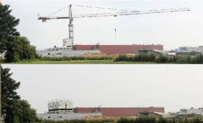
Figure 12: View of the SPIRAL2 phase-1 building construction (July 2013).
At the end of July 2013, all the concrete had been poured (14,000 m3), and the crane removed (Figure 12).
The finishing work, painting, cabling, etc... will continue up to mid 2014.
CONCLUSION
SPIRAL2 is a major nuclear facility that will allow a broad range of research at GANIL. The cryomodules parts are now in a routine assembly process and testing. Six A-type cryomodules have been successfully tested, as well as one B-type cryomodule. This last one has already been delivered to GANIL. The RF tests in the tunnel should start by the last quarter of 2014, as soon as possible and mostly depending on the building availability.
AKNOWLEDGEMENT
The authors address their thanks to the Saclay, IPN-Orsay, LPSC Grenoble and GANIL teams for their wonderful jobs and successes all along the project development.
REFERENCES
[1] http://www.ganil-spiral2.eu/?set_language=en and http://pro.ganil-spiral2.eu/spiral2/what-is-spiral2
[2] MG Saint-Laurent, “Future opportunities with Spiral2 at GANIL”, AccApp07, Pocatello, Idaho, July 30-August 2nd, 2007
[3] M.Lewitowicz “The SPIRAL2 Project: Physics and Challenges”, Zakopane Conference on Nuclear Physics, September 2008
[4] MG Saint-Laurent on behalf of the Spiral2 project group, “Future opportunities with Spiral2 at GANIL”, AccApp07, Pocatello, Idaho, July 30-August 2nd, 2007 [5] P.Bertrand, MH.Moscatello, “The advancement of Spiral2
project”, Cyclotron 2007, Giardini Naxos, Italy, p39-44. [6] JL.Biarrotte et al., “First beams produced by the Spiral2
injectors”, LINAC2010, Tsukuba, Japan.
[7] P. Bertand, R. Ferdinand, "SPIRAL2 accelerator construction progress", Linac 2012, Tel Aviv, Israel [8] P. E.Bernaudin et al, “assembling, testing and
installing the SPIRAL2 superconducting linac”, IPAC 2013, Shangai, China.
c○ 2013 by the respecti v e authors
[9] Y. Gómez-Martínez et al., "Power couplers for SPIRAL2", SRF2011, Berlin.
[10] Y. Gómez-Martínez et al., "Last SPIRAL2 couplers preparation and rf conditioning", this conference
[11] P.-E. Bernaudin & al., “Design of the low beta, quarterwave resonator and its cryomodule for the SPIRAL2 project”, EPAC’04, Lucerne, July 2004. [12] G. Olry & al., “Development of a beta 0.12, 88 MHz,
quarter wave resonator and its cryomodule for the SPIRAL2 project”, SRF’05, Ithaca, July 2005.
[13] PE. Bernaudin et al. “status of the SPIRAL2 superconducnting Linac”, Proceding IPAC’10, Kyoto, Japan.
[14] G. Olry et al, “Spiral2 Cryomodules B Tests Results”, this conference
[15] D. Longuevergne et al, “A Cold Tuner System With Mobile Plunger”
[16] M. Di Giacomo “Acceptance tests for the Spiral2 SC linac RF power systems”, IPAC 2013, Shanghai, China 2013, WEPFI002. c○ 2013 by the respecti v e authors