HAL Id: hal-01611349
https://hal.archives-ouvertes.fr/hal-01611349
Submitted on 18 Jul 2019
HAL is a multi-disciplinary open access
archive for the deposit and dissemination of
sci-entific research documents, whether they are
pub-lished or not. The documents may come from
teaching and research institutions in France or
abroad, or from public or private research centers.
L’archive ouverte pluridisciplinaire HAL, est
destinée au dépôt et à la diffusion de documents
scientifiques de niveau recherche, publiés ou non,
émanant des établissements d’enseignement et de
recherche français ou étrangers, des laboratoires
publics ou privés.
Resistance upset welding of ODS steel fuel claddings
-evolution of a process parameter range based on
metallurgical observations
Fabien Corpace, Arnaud Monnier, Jacques Grall, Jean-Pierre Manaud, Michel
Lahaye, Angeline Poulon-Quintin
To cite this version:
Fabien Corpace, Arnaud Monnier, Jacques Grall, Jean-Pierre Manaud, Michel Lahaye, et al..
Resis-tance upset welding of ODS steel fuel claddings - evolution of a process parameter range based on
metallurgical observations. Metals, MDPI, 2017, 7 (9), pp.333. �10.3390/met7090333�. �hal-01611349�
metals
ArticleResistance Upset Welding of ODS Steel Fuel
Claddings—Evaluation of a Process Parameter Range
Based on Metallurgical Observations
Fabien Corpace1,2, Arnaud Monnier1, Jacques Grall1, Jean-Pierre Manaud2, Michel Lahaye3 and Angeline Poulon-Quintin2,*
1 Den-Service d’Etudes Mécaniques et Thermiques (SEMT), CEA, Université Paris-Saclay,
F-91191 Gif-sur-Yvette, France; fabien.corpace@cea.fr (F.C.); arnaud.monnier@cea.fr (A.M.); jacques.grall@cea.fr (J.G.)
2 Centre National de la Recherche Scientifique (CNRS), University Bordeaux, ICMCB, UPR 9048,
F-33600 Pessac, France; manaud@icmcb-bordeaux.cnrs.fr
3 Surface Analyses Departement, University Bordeaux, Placamat, UMS 3626, F-33600 Pessac, France;
michel.lahaye@placamat.cnrs.fr
* Correspondence: angeline.poulon@icmcb.cnrs.fr; Tel.: +33-540-006-260 Received: 18 July 2017; Accepted: 8 August 2017; Published: 29 August 2017
Abstract:Resistance upset welding is successfully applied to Oxide Dispersion Strengthened (ODS) steel fuel cladding. Due to the strong correlation between the mechanical properties and the microstructure of the ODS steel, this study focuses on the consequences of the welding process on the metallurgical state of the PM2000 ODS steel. A range of process parameters is identified to achieve operative welding. Characterizations of the microstructure are correlated to measurements recorded during the welding process. The thinness of the clad is responsible for a thermal unbalance, leading to a higher temperature reached. Its deformation is important and may lead to a lack of joining between the faying surfaces located on the outer part of the join which can be avoided by increasing the dissipated energy or by limiting the clad stick-out. The deformation and the temperature reached trigger a recrystallization phenomenon in the welded area, usually combined with a modification of the yttrium dispersion, i.e., oxide dispersion, which can damage the long-life resistance of the fuel cladding. The process parameters are optimized to limit the deformation of the clad, preventing the compactness defect and the modification of the nanoscale oxide dispersion.
Keywords:ODS steel; PM2000; oxide dispersion strengthened; welding; resistance welding; fuel cladding; sodium fast reactor; dynamical recrystallization
1. Introduction
Today, energetic needs are increasing and will keep increasing in the coming decades. Nuclear energy is an interesting solution to produce part of this energy. Fourth-generation reactors are being studied and they are foreseen to be operational by the year 2040. The Generation IV International Forum (GIF Symposium, 9–10 September 2009, Paris, France) has identified six concepts of reactors. Among these concepts, Sodium Fast Reactor (SFR) technology is studied in France due to large feedback in Phénix and Superphénix. The generation IV innovative concept of SFR introduces some specifications that are different from those of the past SFR which are not sustained by present materials. Consequently, new materials have to be qualified [1].
In order to increase the efficiency of the new SFR, the fuel cladding material may have to undergo higher dpa (displacement per atom) than the stainless steels previously used and presented in Nuclear systems of the future generation IV. Potential substitutes are Oxide Dispersion Strengthened (ODS)
Metals 2017, 7, 333 2 of 11
alloys due to promising corrosion and neutron behavior and good high temperature mechanical properties. These properties are the consequence of a homogeneous dispersion of nanoscale oxide particles inside the metallic matrix [2].
If the ODS material transitions to a molten phase during the fabrication route and especially during the assembling step, the nanoscale particles may be reallocated in the matrix and the initial oxide dispersion may be modified. Consequently, solid-state welding processes are promising [3,4].
Among the solid-state welding processes, resistance upset welding has been successfully applied to various ODS alloys for several fuel pin cladding applications [5–10]. These studies focused on mechanical test results. The welds are characterized using mechanical testing up to 800◦C by traction, burst test, creep or fatigue. Little or no information is related to microstructure evolution or oxide distribution evolution. However, metallurgical analyses have been conducted on several ODS alloys welded by different processes such as inertia friction welding [11], friction stir welding [12–14] and diffusion bounding [15]. It appears that these processes can induce modification of the metallurgical state, including dynamic recrystallisation, modification in grain orientation or modification in the oxide dispersion. Some rupture in these modified areas is reported [4,11].
The modifications of the microstructure, occurring during solid-state bonding, may lead to possible changes in the mechanical properties. A lack of metallurgical studies on resistance upset welding on ODS alloys has been identified. This study focuses on the metallurgical evolution during resistance upset welding applied to cladding made in a ferritic ODS alloy (PM2000). Evidence of modifications of the nanoscale oxide dispersion is shown. Therefore, the process parameters have to be optimized in order to produce welds with good compactness and no modification of the oxide distribution.
2. Materials and Methods
2.1. Material and Geometry
The studied material is PM2000 in the recrystallized form (millimeter-sized grains) produced by PLANSEE (Metallwerk Plansee GmbH, Lechbruck am See, Germany). It is a ferritic ODS alloy strengthened by nano-oxides composed of yttria (size <50 nm) or Aluminum and yttria (size < 100 nm). Its composition is presented in Table1.
Table 1.PM2000 nominal composition (wt %).
Fe Cr Al Ti Y2O3
Balanced 20 5.5 0.5 0.5
The pieces to be welded are a clad and an end plug. The clad has an outside diameter of 10.5 mm and a thickness equal to 0.5 mm. The end plug has a diameter of 10.5 mm. The contact surfaces are chamfered with an angle of 45◦. Figure1shows the pieces to be welded: clad and end plug.
Metals 2017, 7, 333 2 of 11
Strengthened (ODS) alloys due to promising corrosion and neutron behavior and good high temperature mechanical properties. These properties are the consequence of a homogeneous dispersion of nanoscale oxide particles inside the metallic matrix [2].
If the ODS material transitions to a molten phase during the fabrication route and especially during the assembling step, the nanoscale particles may be reallocated in the matrix and the initial oxide dispersion may be modified. Consequently, solid-state welding processes are promising [3,4].
Among the solid-state welding processes, resistance upset welding has been successfully applied to various ODS alloys for several fuel pin cladding applications [5–10]. These studies focused on mechanical test results. The welds are characterized using mechanical testing up to 800 °C by traction, burst test, creep or fatigue. Little or no information is related to microstructure evolution or oxide distribution evolution. However, metallurgical analyses have been conducted on several ODS alloys welded by different processes such as inertia friction welding [11], friction stir welding [12–14] and diffusion bounding [15]. It appears that these processes can induce modification of the metallurgical state, including dynamic recrystallisation, modification in grain orientation or modification in the oxide dispersion. Some rupture in these modified areas is reported [4,11].
The modifications of the microstructure, occurring during solid-state bonding, may lead to possible changes in the mechanical properties. A lack of metallurgical studies on resistance upset welding on ODS alloys has been identified. This study focuses on the metallurgical evolution during resistance upset welding applied to cladding made in a ferritic ODS alloy (PM2000). Evidence of modifications of the nanoscale oxide dispersion is shown. Therefore, the process parameters have to be optimized in order to produce welds with good compactness and no modification of the oxide distribution.
2. Materials and Methods
2.1. Material and Geometry
The studied material is PM2000 in the recrystallized form (millimeter-sized grains) produced by PLANSEE (Metallwerk Plansee GmbH, Lechbruck am See, Germany). It is a ferritic ODS alloy strengthened by nano-oxides composed of yttria (size <50 nm) or Aluminum and yttria (size < 100 nm). Its composition is presented in Table 1.
Table 1. PM2000 nominal composition (wt %).
Fe Cr Al Ti Y2O3
Balanced 20 5.5 0.5 0.5
The pieces to be welded are a clad and an end plug. The clad has an outside diameter of 10.5 mm and a thickness equal to 0.5 mm. The end plug has a diameter of 10.5 mm. The contact surfaces are chamfered with an angle of 45°. Figure 1 shows the pieces to be welded: clad and end plug.
Figure 1. Pieces to be welded: end plug and clad. 2.2. Resistance Welding Process
The resistance welding process is composed of three main steps [16] represented in Figure 2: the squeezing phase, the welding phase and the forging phase. The two pieces to be welded are circled
Figure 1.Pieces to be welded: end plug and clad.
2.2. Resistance Welding Process
The resistance welding process is composed of three main steps [16] represented in Figure2: the squeezing phase, the welding phase and the forging phase. The two pieces to be welded are
Metals 2017, 7, 333 3 of 11
circled by two electrodes. The length of the clad that is out of the electrode, called “clad stick-out” (Cs),
is considered as a process parameter as demonstrated in a previous paper [17] and observed by other authors on other materials [7,9]. During the squeezing phase, the two pieces to be welded are put and held in contact by a contact force Fw. The next step is the welding phase: a current with an intensity Iw
is imposed through the two pieces in contact for a duration tw. The Joule effect generates heat in the
materials, especially near the contact surfaces between the two pieces. Then, during the forging phase, the current is stopped and the contact force Fwis upheld until the cooling of the weldment is complete.
by two electrodes. The length of the clad that is out of the electrode, called “clad stick-out” (Cs), is
considered as a process parameter as demonstrated in a previous paper [17] and observed by other authors on other materials [7,9]. During the squeezing phase, the two pieces to be welded are put and held in contact by a contact force Fw. The next step is the welding phase: a current with an intensity
Iw is imposed through the two pieces in contact for a duration tw. The Joule effect generates heat in
the materials, especially near the contact surfaces between the two pieces. Then, during the forging phase, the current is stopped and the contact force Fw is upheld until the cooling of the weldment is
complete.
Figure 2. Schematic scenario of the resistance upset welding steps. 2.3. Experimental Device and Measurements
The experimental device has been developed for the considered geometry and is fabricated by the French company “TECHNAX industrie” (Saint-Priest, France). The device is composed of three parts:
• An electrical device: This part is composed of transformers and rectifiers delivering a rectified smoothed current with a frequency of 2 kHz;
• A control device: This part allows the setting of the process parameters (contact force Fw, current
intensity Iw, welding time tw);
• A welding device: A schematic view of this part is shown in Figure 3.
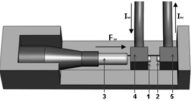
Figure 3. Schematic view of the welding device (Fw = welding force; Iw: welding current intensity; 1: end plug; 2: clad; 3: pneumatic jack; 4 and 5: electrodes).
The end plug (1) and the clad (2) to be welded are circled by two electrodes (4 and 5). The end plug and its electrodes are attached to the moving part of the device whereas the clad and its electrode are attached to the frame of the device and are motionless. The contact force is applied by means of a pneumatic jack (3) that put in contact the two pieces to be welded (1 and 2). Once the mechanical contact is established (the squeezing phase), the electrical device imposes the current through the two pieces by means of the electrodes.
The device is instrumented to measure the current intensity I(t), the axial position of the mobile part x(t), the electrical potential between the electrodes Uelec(t) and the force F(t) every 10 µs. From
these measurements, it is possible to compute two values:
The dissipated energy at the end of the process Eend represents the amount of electrical energy
dissipated in the welded pieces and the electrodes at the end of the welding process. This value is computed according to the following equation:
Figure 2.Schematic scenario of the resistance upset welding steps.
2.3. Experimental Device and Measurements
The experimental device has been developed for the considered geometry and is fabricated by the French company “TECHNAX industrie” (Saint-Priest, France). The device is composed of three parts:
• An electrical device: This part is composed of transformers and rectifiers delivering a rectified smoothed current with a frequency of 2 kHz;
• A control device: This part allows the setting of the process parameters (contact force Fw,
current intensity Iw, welding time tw);
• A welding device: A schematic view of this part is shown in Figure3.
by two electrodes. The length of the clad that is out of the electrode, called “clad stick-out” (Cs), is
considered as a process parameter as demonstrated in a previous paper [17] and observed by other authors on other materials [7,9]. During the squeezing phase, the two pieces to be welded are put and held in contact by a contact force Fw. The next step is the welding phase: a current with an intensity
Iw is imposed through the two pieces in contact for a duration tw. The Joule effect generates heat in
the materials, especially near the contact surfaces between the two pieces. Then, during the forging phase, the current is stopped and the contact force Fw is upheld until the cooling of the weldment is
complete.
Figure 2. Schematic scenario of the resistance upset welding steps. 2.3. Experimental Device and Measurements
The experimental device has been developed for the considered geometry and is fabricated by the French company “TECHNAX industrie” (Saint-Priest, France). The device is composed of three parts:
• An electrical device: This part is composed of transformers and rectifiers delivering a rectified smoothed current with a frequency of 2 kHz;
• A control device: This part allows the setting of the process parameters (contact force Fw, current
intensity Iw, welding time tw);
• A welding device: A schematic view of this part is shown in Figure 3.
Figure 3. Schematic view of the welding device (Fw = welding force; Iw: welding current intensity; 1: end plug; 2: clad; 3: pneumatic jack; 4 and 5: electrodes).
The end plug (1) and the clad (2) to be welded are circled by two electrodes (4 and 5). The end plug and its electrodes are attached to the moving part of the device whereas the clad and its electrode are attached to the frame of the device and are motionless. The contact force is applied by means of a pneumatic jack (3) that put in contact the two pieces to be welded (1 and 2). Once the mechanical contact is established (the squeezing phase), the electrical device imposes the current through the two pieces by means of the electrodes.
The device is instrumented to measure the current intensity I(t), the axial position of the mobile part x(t), the electrical potential between the electrodes Uelec(t) and the force F(t) every 10 µs. From
these measurements, it is possible to compute two values:
The dissipated energy at the end of the process Eend represents the amount of electrical energy
dissipated in the welded pieces and the electrodes at the end of the welding process. This value is computed according to the following equation:
Figure 3.Schematic view of the welding device (Fw= welding force; Iw: welding current intensity;
1: end plug; 2: clad; 3: pneumatic jack; 4 and 5: electrodes).
The end plug (1) and the clad (2) to be welded are circled by two electrodes (4 and 5). The end plug and its electrodes are attached to the moving part of the device whereas the clad and its electrode are attached to the frame of the device and are motionless. The contact force is applied by means of a pneumatic jack (3) that put in contact the two pieces to be welded (1 and 2). Once the mechanical contact is established (the squeezing phase), the electrical device imposes the current through the two pieces by means of the electrodes.
The device is instrumented to measure the current intensity I(t), the axial position of the mobile part x(t), the electrical potential between the electrodes Uelec(t) and the force F(t) every 10 µs.
Metals 2017, 7, 333 4 of 11
The dissipated energy at the end of the process Eendrepresents the amount of electrical energy
dissipated in the welded pieces and the electrodes at the end of the welding process. This value is computed according to the following equation:
Eend= t=tend
Z
t=0
Uelec(t) ×I(t) ×dt (1)
The collapse value is the length change of the pieces during the welding phase. 2.4. Sample Preparation and Observation
The welded pieces are cut along one diameter. Therefore, the weld can be observed in two locations, one face located at 180◦of the other. All welds are observed using an optical microscope (Zeiss, München, Germany) before and after a metallographic etch (20 s in 20 mL H2O–20 mL HCl–15 mL HNO3).
The yttrium dispersion is characterized (localization and quantification) using a CAMECA SX100 (CAMECA, Gennevilliers, France) microprobe at 20 kV with a step of 1 µm and a dwelling time of 7 ms. Therefore, only the modifications at a microscopic level are observed. Back Scattering Electron (BSE) observations have been conducted on some welds using the same device.
3. Results
In this study, we deliberately made different kinds of weld—from good quality weld to weld with obvious defects. The aim is to have a good understanding of the formation of the welds in order to avoid the defects. The process parameter range is listed in Table2. In the following, the process parameters will be quoted as a quadruplet (Fw; Iw; tw; Cs).
Table 2.Process parameter range.
Name Description Min. Max.
Fw Force (N) 1800 2200
Iw Current intensity (kA) 14 18
tw Welding time (ms) 10 15
Cs Clad stick-out (mm) 0.2 0.8
It has to be noted that some welds present a compactness defect on one of their faces due to material ejection. These material ejections are under investigation but their location seems to incriminate the electrode—clad electrical contact. The faces presenting these defects are not taken into account and are rejected from the metallurgical analysis.
3.1. Welding Mechanism on Typical Welds
Figure4shows a typical weld with good compactness, a continuous interface and no modification of the yttrium distribution except in the internal upset. The modifications in the upsets are supposed to have no importance in the mechanical properties of the weld due to their positions outside the welded joint. The observations in the end plug, “far” from the joint, are representative of the base material due to the low temperature and the negligible deformation reached in this part [17]. Cavities are due to the fabrication route.
Figure 4. Wavelength-dispersive spectroscopy (WDS) analysis of a welded zone with (Fw; Iw; tw; Cs) = (1800 N; 14 kA; 15 ms; 0.8 mm): (a) Back Scattering Electron (BSE) picture; (b) Corresponding yttrium distribution.
The thinness of the clad compared to the bulk end plug creates a thermal unbalance, leading to higher temperatures in the clad than in the plug. Therefore, the clad is always more deformed than the end plug. The electrode achieves both the cooling and the clamping of the clad and therefore the highest deformations are localized in the clad part that is not in contact with the electrode (clad part out of the electrode).
3.2. Typical Deformation
The typical deformation of the clad is highlighted in Figure 5 where an elongated grain can be used to observe the deformation. The shape of the outer upset shows that the clad is sliding along the 45° chamfer of the end plug. This upset will be removed for the SFR application. The sliding creates a high deformation area (with an S-shaped grain) near the contact between the clad and the electrode.
Figure 5. Evidence of the material deformation with the selected parameters (Fw; Iw; tw; Cs) = (2600 N; 14 kA; 10 ms; 0.8 mm).
In the internal side, the upset is composed of solidified grains due to expulsed molten materials during welding. Heated materials (below melting temperature) seem to have flown from the clad to the internal upset and are then trapped between the pieces. The deformation of the clad can be monitored by the measurement of the collapse value. The collapse value versus the dissipated energy
Figure 4.Wavelength-dispersive spectroscopy (WDS) analysis of a welded zone with (Fw; Iw; tw; Cs)
= (1800 N; 14 kA; 15 ms; 0.8 mm): (a) Back Scattering Electron (BSE) picture; (b) Corresponding yttrium distribution.
The thinness of the clad compared to the bulk end plug creates a thermal unbalance, leading to higher temperatures in the clad than in the plug. Therefore, the clad is always more deformed than the end plug. The electrode achieves both the cooling and the clamping of the clad and therefore the highest deformations are localized in the clad part that is not in contact with the electrode (clad part out of the electrode).
3.2. Typical Deformation
The typical deformation of the clad is highlighted in Figure5where an elongated grain can be used to observe the deformation. The shape of the outer upset shows that the clad is sliding along the 45◦chamfer of the end plug. This upset will be removed for the SFR application. The sliding creates a high deformation area (with an S-shaped grain) near the contact between the clad and the electrode.
Figure 4. Wavelength-dispersive spectroscopy (WDS) analysis of a welded zone with (Fw; Iw; tw; Cs) = (1800 N; 14 kA; 15 ms; 0.8 mm): (a) Back Scattering Electron (BSE) picture; (b) Corresponding yttrium distribution.
The thinness of the clad compared to the bulk end plug creates a thermal unbalance, leading to higher temperatures in the clad than in the plug. Therefore, the clad is always more deformed than the end plug. The electrode achieves both the cooling and the clamping of the clad and therefore the highest deformations are localized in the clad part that is not in contact with the electrode (clad part out of the electrode).
3.2. Typical Deformation
The typical deformation of the clad is highlighted in Figure 5 where an elongated grain can be used to observe the deformation. The shape of the outer upset shows that the clad is sliding along the 45° chamfer of the end plug. This upset will be removed for the SFR application. The sliding creates a high deformation area (with an S-shaped grain) near the contact between the clad and the electrode.
Figure 5. Evidence of the material deformation with the selected parameters (Fw; Iw; tw; Cs) = (2600 N; 14 kA; 10 ms; 0.8 mm).
In the internal side, the upset is composed of solidified grains due to expulsed molten materials during welding. Heated materials (below melting temperature) seem to have flown from the clad to the internal upset and are then trapped between the pieces. The deformation of the clad can be monitored by the measurement of the collapse value. The collapse value versus the dissipated energy
Figure 5.Evidence of the material deformation with the selected parameters (Fw; Iw; tw; Cs) = (2600 N;
14 kA; 10 ms; 0.8 mm).
In the internal side, the upset is composed of solidified grains due to expulsed molten materials during welding. Heated materials (below melting temperature) seem to have flown from the clad to the internal upset and are then trapped between the pieces. The deformation of the clad can be
Metals 2017, 7, 333 6 of 11
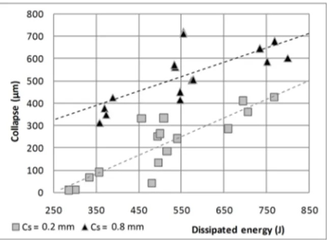
monitored by the measurement of the collapse value. The collapse value versus the dissipated energy for 32 experiments within the process parameter range is plotted in Figure6for two different clad stick-outs. The collapse (i.e., the deformation) increases when the dissipated energy increases for a given Csvalue. A high stick-out-value leads to a higher collapse value. It has to be noted that the
collapse can be higher than Csdue to an irregular hand-made chamfer on the electrode (cf. Figure2).
Metals 2017, 7, 333 6 of 11
for 32 experiments within the process parameter range is plotted in Figure 6 for two different clad stick-outs. The collapse (i.e., the deformation) increases when the dissipated energy increases for a given Cs value. A high stick-out-value leads to a higher collapse value. It has to be noted that the
collapse can be higher than Cs due to an irregular hand-made chamfer on the electrode (cf. Figure 2).
Figure 6. Collapse value as a function of the dissipated energy for 32 experiments. 3.3. Welds with a Low Dissipated Energy
A weld achieved with process parameters leading to a low dissipated energy (370 J) is shown in Figure 7. In the outer part of the weld joint, the faying surfaces are insufficiently joined. This spacing between the faying surfaces will be called a lack of joining in the following.
Figure 7. Example of a lack of joining (Mirror polish without etching) for a sample welded with the selected parameters (Fw; Iw; tw; Cs) = (2600 N; 14 kA; 10 ms; 0.8 mm).
For all the welds presenting a lack of joining, their localization is always in the outer part of the weld, roughly at the same place as shown in Figure 7. For each weld, two faces are observed and the length of this lack of joining can be measured.
The “not welded length” plotted in Figure 8 as a function of the dissipated energy is the average value of these two measures. It appears that an increase in the dissipated energy leads to a decrease of the not welded length. For a shorter clad stick-out, the dissipated energy required to achieve welds with no lack of joining on both sides is lower (450 J) than the dissipated energy required for a high value of clad stick-out (530 J).
Figure 6.Collapse value as a function of the dissipated energy for 32 experiments.
3.3. Welds with a Low Dissipated Energy
A weld achieved with process parameters leading to a low dissipated energy (370 J) is shown in Figure7. In the outer part of the weld joint, the faying surfaces are insufficiently joined. This spacing between the faying surfaces will be called a lack of joining in the following.
Metals 2017, 7, 333 6 of 11
for 32 experiments within the process parameter range is plotted in Figure 6 for two different clad stick-outs. The collapse (i.e., the deformation) increases when the dissipated energy increases for a given Cs value. A high stick-out-value leads to a higher collapse value. It has to be noted that the
collapse can be higher than Cs due to an irregular hand-made chamfer on the electrode (cf. Figure 2).
Figure 6. Collapse value as a function of the dissipated energy for 32 experiments. 3.3. Welds with a Low Dissipated Energy
A weld achieved with process parameters leading to a low dissipated energy (370 J) is shown in Figure 7. In the outer part of the weld joint, the faying surfaces are insufficiently joined. This spacing between the faying surfaces will be called a lack of joining in the following.
Figure 7. Example of a lack of joining (Mirror polish without etching) for a sample welded with the selected parameters (Fw; Iw; tw; Cs) = (2600 N; 14 kA; 10 ms; 0.8 mm).
For all the welds presenting a lack of joining, their localization is always in the outer part of the weld, roughly at the same place as shown in Figure 7. For each weld, two faces are observed and the length of this lack of joining can be measured.
The “not welded length” plotted in Figure 8 as a function of the dissipated energy is the average value of these two measures. It appears that an increase in the dissipated energy leads to a decrease of the not welded length. For a shorter clad stick-out, the dissipated energy required to achieve welds with no lack of joining on both sides is lower (450 J) than the dissipated energy required for a high value of clad stick-out (530 J).
Figure 7.Example of a lack of joining (Mirror polish without etching) for a sample welded with the selected parameters (Fw; Iw; tw; Cs) = (2600 N; 14 kA; 10 ms; 0.8 mm).
For all the welds presenting a lack of joining, their localization is always in the outer part of the weld, roughly at the same place as shown in Figure7. For each weld, two faces are observed and the length of this lack of joining can be measured.
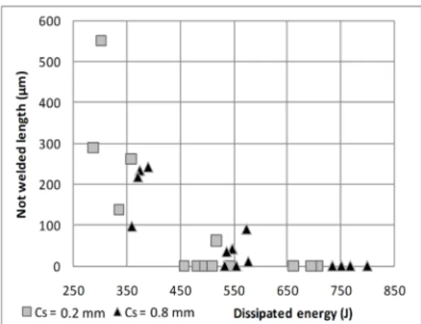
The “not welded length” plotted in Figure8as a function of the dissipated energy is the average value of these two measures. It appears that an increase in the dissipated energy leads to a decrease of the not welded length. For a shorter clad stick-out, the dissipated energy required to achieve welds with no lack of joining on both sides is lower (450 J) than the dissipated energy required for a high value of clad stick-out (530 J).
Figure 8. Not welded length as a function of the dissipated energy for 32 experiments. 3.4. Welds with a High Collapse
A weld achieved with process parameters leading to a high dissipated energy (537 J) is shown in Figure 9. Some modifications of the microstructure and of the yttrium dispersion are observed in the inner upset, at the interface and in the clad. The modified part in the clad starts from the electrode– clad contact area and extends to the joint. The black dots on the etched pictures correspond to a fine grain microstructure that is characteristic of a dynamical recrystallisation phenomenon. As shown in the yttrium distribution mapping, the modifications of the oxide dispersion occur specifically in the area where a recrystallisation phenomenon occurred. Clusters with a high density of yttrium surrounded by an area with a deficit in yttrium contents are noticeable.
Figure 9. Evidence of modification of the metallurgical state of the sample welded using the parameters (Fw; Iw; tw; Cs) = (2600 N; 18 kA; 10 ms; 0.8 mm). (a) Optical micrograph of an etched sample; (b) WDS Yttrium distribution.
It has to be noted that all the welds presenting a modification of the yttrium distribution at the interface also presented a modification near the electrode–clad contact. It shows that recrystallization may first take place at the electrode–clad contact and then spread to the interface and to the inner upset. As a result, in Table 3, the modified area has been ranged from 0 to 4 (arbitrary unit) according to its shape and its extent.
Figure 8.Not welded length as a function of the dissipated energy for 32 experiments.
3.4. Welds with a High Collapse
A weld achieved with process parameters leading to a high dissipated energy (537 J) is shown in Figure9. Some modifications of the microstructure and of the yttrium dispersion are observed in the inner upset, at the interface and in the clad. The modified part in the clad starts from the electrode–clad contact area and extends to the joint. The black dots on the etched pictures correspond to a fine grain microstructure that is characteristic of a dynamical recrystallisation phenomenon. As shown in the yttrium distribution mapping, the modifications of the oxide dispersion occur specifically in the area where a recrystallisation phenomenon occurred. Clusters with a high density of yttrium surrounded by an area with a deficit in yttrium contents are noticeable.
Figure 8. Not welded length as a function of the dissipated energy for 32 experiments. 3.4. Welds with a High Collapse
A weld achieved with process parameters leading to a high dissipated energy (537 J) is shown in Figure 9. Some modifications of the microstructure and of the yttrium dispersion are observed in the inner upset, at the interface and in the clad. The modified part in the clad starts from the electrode– clad contact area and extends to the joint. The black dots on the etched pictures correspond to a fine grain microstructure that is characteristic of a dynamical recrystallisation phenomenon. As shown in the yttrium distribution mapping, the modifications of the oxide dispersion occur specifically in the area where a recrystallisation phenomenon occurred. Clusters with a high density of yttrium surrounded by an area with a deficit in yttrium contents are noticeable.
Figure 9. Evidence of modification of the metallurgical state of the sample welded using the parameters (Fw; Iw; tw; Cs) = (2600 N; 18 kA; 10 ms; 0.8 mm). (a) Optical micrograph of an etched sample; (b) WDS Yttrium distribution.
It has to be noted that all the welds presenting a modification of the yttrium distribution at the interface also presented a modification near the electrode–clad contact. It shows that recrystallization may first take place at the electrode–clad contact and then spread to the interface and to the inner upset. As a result, in Table 3, the modified area has been ranged from 0 to 4 (arbitrary unit) according to its shape and its extent.
Figure 9.Evidence of modification of the metallurgical state of the sample welded using the parameters (Fw; Iw; tw; Cs) = (2600 N; 18 kA; 10 ms; 0.8 mm). (a) Optical micrograph of an etched sample; (b) WDS
Yttrium distribution.
It has to be noted that all the welds presenting a modification of the yttrium distribution at the interface also presented a modification near the electrode–clad contact. It shows that recrystallization may first take place at the electrode–clad contact and then spread to the interface and to the inner upset. As a result, in Table3, the modified area has been ranged from 0 to 4 (arbitrary unit) according to its shape and its extent.
Metals 2017, 7, 333 8 of 11
Table 3.Classification used for the yttrium distribution modification.
Arbitrary Unit Shape and Extent
0 No yttrium modifications
1 Modification localised in the outer part of the joint with possible extension to the outer upset 2 Modification in the clad near the electrode piece contact
3 2 + spreading to the interface
4 3 + spreading through the interface to the inner upset
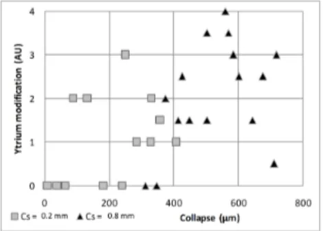
Two faces of the same weld are observed and two values are assigned. The “yttrium modification” plotted in Figure10as a function of the collapse value, is the average of these two values.
Metals 2017, 7, 333 8 of 11
Table 3. Classification used for the yttrium distribution modification.
Arbitrary Unit Shape and Extent
0 No yttrium modifications
1 Modification localised in the outer part of the joint with possible extension to the outer upset
2 Modification in the clad near the electrode piece contact
3 2 + spreading to the interface
4 3 + spreading through the interface to the inner upset
Two faces of the same weld are observed and two values are assigned. The “yttrium modification” plotted in Figure 10 as a function of the collapse value, is the average of these two values.
Figure 10. Yttrium modification (arbitrary unit defined in Table 3) as a function of collapse value.
It appears that the yttria modification is more important when the collapse increases. A short clad stick-out reduces the collapse and the welds with no yttrium modification are more numerous in this configuration
4. Discussion
The objective is to find a range of dissipated energy (i.e., process parameters) to achieve welds with no lack of joining between the pieces and no modification of the oxide dispersion.
4.1. Lack of Joining between the Pieces
A lack of joining can appear in the outer part of the joint due to two phenomena:
• An electro-thermal phenomenon: The current flow is constricted in the inner part of the weld joint because of the bulk end plug in contact with the thin clad. A higher current density in the internal part of the welded joint leads to a higher temperature in this part than in the outer part of the joint. This phenomenon has been simulated by Zirker [8] using electrothermal computation on tube-rod geometry but no experimental evidence was shown. The observations of the material flow on the inner part of the joint give credit to Zirker’s simulation.
• A thermo-mechanical phenomenon: The clad heats up faster than the end plug (due to the thermal unbalance) resulting in softening the part of the clad out of the electrode. The applied force and the 45° chamfer create a radial force, resulting in the sliding of the clad on the 45° chamfer. This sliding can open the contact in the outer part, preventing its welding.
The lack of joining can be avoided with an increase of the dissipated energy (Figure 8), leading to a higher collapse. Therefore, the end plug penetrates farther in the clad, closing the gap between the clad and the end plug created during the sliding of the clad. Moreover, increasing the energy increased the overall heat-up, resulting in a higher temperature in the outer part of the joint, preventing the defects.
Figure 10.Yttrium modification (arbitrary unit defined in Table3) as a function of collapse value.
It appears that the yttria modification is more important when the collapse increases. A short clad stick-out reduces the collapse and the welds with no yttrium modification are more numerous in this configuration.
4. Discussion
The objective is to find a range of dissipated energy (i.e., process parameters) to achieve welds with no lack of joining between the pieces and no modification of the oxide dispersion.
4.1. Lack of Joining between the Pieces
A lack of joining can appear in the outer part of the joint due to two phenomena:
• An electro-thermal phenomenon: The current flow is constricted in the inner part of the weld joint because of the bulk end plug in contact with the thin clad. A higher current density in the internal part of the welded joint leads to a higher temperature in this part than in the outer part of the joint. This phenomenon has been simulated by Zirker [8] using electrothermal computation on tube-rod geometry but no experimental evidence was shown. The observations of the material flow on the inner part of the joint give credit to Zirker’s simulation.
• A thermo-mechanical phenomenon: The clad heats up faster than the end plug (due to the thermal unbalance) resulting in softening the part of the clad out of the electrode. The applied force and the 45◦ chamfer create a radial force, resulting in the sliding of the clad on the 45◦ chamfer. This sliding can open the contact in the outer part, preventing its welding.
The lack of joining can be avoided with an increase of the dissipated energy (Figure8), leading to a higher collapse. Therefore, the end plug penetrates farther in the clad, closing the gap between the clad and the end plug created during the sliding of the clad. Moreover, increasing the energy increased the overall heat-up, resulting in a higher temperature in the outer part of the joint, preventing the defects.
A decrease in the clad stick-out reduces the not welded length. Decreasing the clad stick-out can increase the stiffness of the clad part out of the electrode and should prevent the opening of the contact by limiting the tube deformation and its sliding.
4.2. Yttrium Modifications
A modification of the yttrium dispersion can lead to a long-term failure of the weldment due to weakness points created by the lack of anchors to dislocation movement. The yttrium modification is observed in areas where recrystallization occurred.
An increase in the modification extent occurs when the collapse increases (Figure10). The collapse value is highly influenced by the clad stick-out and the dissipated energy (Figure6). As the collapse increases, the clad deformation increases which combined with a high temperature can trigger the dynamical recrystallization. Modified area localizations observed in Section3.4are consistent with the area of high deformation observed in Section3.2.
Some authors have proposed some mechanisms in order to correlate the recrystallization and the modification of the Yttrium. Zhang et al. [15] proposed an interaction mechanism between oxides and dislocations to explain the modification of the oxide dispersion during diffusion bonding of an ODS alloy. Based on the works of Yazawa et al. [18], Yamamoto et al. [19] proposed that the oxide dispersion can be modified during phase transformation of a 9% Cr ODS-alloy due to a modification in the matrix-oxide coherency. Both dislocation movement and modification of the grain orientations occur during dynamical recrystallization. Therefore, both hypotheses may explain the modification in the yttrium distribution where the dynamical recrystallization occurred.
4.3. Optimizing Resistance Upset Welding for ODS Steel Fuel Cladding
Two types of defects to avoid are identified: a lack of joining between the pieces and a significant modification of the Yttrium dispersion observable in WDS analyses.
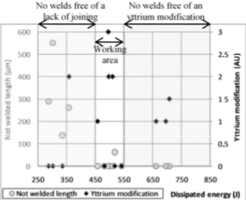
The lack of joining between the pieces can be avoided by increasing the dissipated energy. None of the welds below E = 450 J are free of this lack of joining (this value reached 530 J for Cs= 0.8 mm). Therefore, for Cs= 0.2 mm, the dissipated energy must be higher than 450 J.
The Yttrium modification can be avoided by decreasing the collapse. The collapse is mainly influenced by the dissipated energy and the clad stick-out. None of the welds above E = 550 J are free of the modification in the yttrium distribution (this value drops to 375 J for Cs= 0.8 mm). Therefore,
for Cs= 0.2 mm, the dissipated energy must be lower than 550 J. Below 550 J, some welds still present
a modification of the yttrium distribution and other parameters have to be adjusted to avoid all the defects in this area.
For a clad stick-out of 0.2 mm, a working area exists where welds free of both defects are produced. This working area does not exist for a clad stick-out of 0.8 mm.
The working area is illustrated in Figure11. The working area is located in a range of dissipated energy between 450 and 550 J. The energy range may be highly dependent on the process route.
Metals 2017, 7, 333 9 of 11
A decrease in the clad stick-out reduces the not welded length. Decreasing the clad stick-out can increase the stiffness of the clad part out of the electrode and should prevent the opening of the contact by limiting the tube deformation and its sliding.
4.2. Yttrium Modifications
A modification of the yttrium dispersion can lead to a long-term failure of the weldment due to weakness points created by the lack of anchors to dislocation movement. The yttrium modification is observed in areas where recrystallization occurred.
An increase in the modification extent occurs when the collapse increases (Figure 10). The collapse value is highly influenced by the clad stick-out and the dissipated energy (Figure 6). As the collapse increases, the clad deformation increases which combined with a high temperature can trigger the dynamical recrystallization. Modified area localizations observed in Section 3.4 are consistent with the area of high deformation observed in Section 3.2.
Some authors have proposed some mechanisms in order to correlate the recrystallization and the modification of the Yttrium. Zhang et al. [15] proposed an interaction mechanism between oxides and dislocations to explain the modification of the oxide dispersion during diffusion bonding of an ODS alloy. Based on the works of Yazawa et al. [18], Yamamoto et al. [19] proposed that the oxide dispersion can be modified during phase transformation of a 9% Cr ODS-alloy due to a modification in the matrix-oxide coherency. Both dislocation movement and modification of the grain orientations occur during dynamical recrystallization. Therefore, both hypotheses may explain the modification in the yttrium distribution where the dynamical recrystallization occurred.
4.3. Optimizing Resistance Upset Welding for ODS Steel Fuel Cladding
Two types of defects to avoid are identified: a lack of joining between the pieces and a significant modification of the Yttrium dispersion observable in WDS analyses.
The lack of joining between the pieces can be avoided by increasing the dissipated energy. None of the welds below E = 450 J are free of this lack of joining (this value reached 530 J for Cs = 0.8 mm).
Therefore, for Cs = 0.2 mm, the dissipated energy must be higher than 450 J.
The Yttrium modification can be avoided by decreasing the collapse. The collapse is mainly influenced by the dissipated energy and the clad stick-out. None of the welds above E = 550 J are free of the modification in the yttrium distribution (this value drops to 375 J for Cs = 0.8 mm). Therefore,
for Cs = 0.2 mm, the dissipated energy must be lower than 550 J. Below 550 J, some welds still present
a modification of the yttrium distribution and other parameters have to be adjusted to avoid all the defects in this area.
For a clad stick-out of 0.2 mm, a working area exists where welds free of both defects are produced. This working area does not exist for a clad stick-out of 0.8 mm.
The working area is illustrated in Figure 11. The working area is located in a range of dissipated energy between 450 and 550 J. The energy range may be highly dependent on the process route.
Figure 11.Range of the allowable dissipated energy to achieve welds with no lack of joining and no yttrium modifications (Cs= 0.2 mm).
Metals 2017, 7, 333 10 of 11
However, some welds in the working area present an yttrium modification and/or a lack of joining due to other process parameters that should be optimized as well. A weld produced in this range and free of both defects is presented in Figure12. After optimization, the reproducibility of the process for the optimized process routes is observed.
Metals 2017, 7, 333 10 of 11
Figure 11. Range of the allowable dissipated energy to achieve welds with no lack of joining and no yttrium modifications (Cs = 0.2 mm).
However, some welds in the working area present an yttrium modification and/or a lack of joining due to other process parameters that should be optimized as well. A weld produced in this range and free of both defects is presented in Figure 12. After optimization, the reproducibility of the process for the optimized process routes is observed.
Figure 12. WDS yttrium distribution for a weld within the working area with the selected parameters (Fw; Iw; tw; Cs) = (2400 N; 14 kA; 15 ms; 0.2 mm).
5. Conclusions
Resistance upset welding has been applied with success to the ODS steel PM2000 (20% Cr) for the SFR fuel cladding application. For the given process parameters range, welds with different qualities have been produced. The main conclusions are:
• The clad part out of the electrode is highly deformed during the process due to thermal unbalance between the clad and the plug.
• For a high dissipated energy and a high collapse, the deformation of the clad can generate recrystallization phenomena associated with a modification of the yttria distribution.
• For a low dissipated energy, the faying surfaces can be insufficiently joined on the outer part of the join.
• For a clad stick-out of 0.2 mm, a range of dissipated energies exists where weldments with no significant yttria distribution modification and no lack of joining between pieces can be produced.
Other process parameters, such as the geometry of the contact surfaces, could be optimized in order to limit the deformation and avoid the lack of joining between pieces. The mechanical properties of the modified area should also be studied because a given amount of yttrium modification may be acceptable, rising the upper limit of the dissipated energy.
Acknowledgments: This work is part of PhD between the Institut de Chimie de la Matière Condensée de Bordeaux (ICMCB) and the Commissariat à l’énergie atomique et aux énergies alternatives (CEA-Saclay). The PhD is part of a research program for materials suitable for Sodium Fast Reactor (SFR) financed by CEA, Areva NP (Areva Nuclear Power) and EDF (Électricité De France).
Author Contributions: Fabien Corpace is the Ph.D. student. He wrote the paper, Arnaud Monnier, Jean-Pierre Manaud and Angeline Poulon-Quintin directed his work. Michel Lahaye performed the WDS experiments; Jacques Grall contributed to sample preparation.
Figure 12.WDS yttrium distribution for a weld within the working area with the selected parameters (Fw; Iw; tw; Cs) = (2400 N; 14 kA; 15 ms; 0.2 mm).
5. Conclusions
Resistance upset welding has been applied with success to the ODS steel PM2000 (20% Cr) for the SFR fuel cladding application. For the given process parameters range, welds with different qualities have been produced. The main conclusions are:
• The clad part out of the electrode is highly deformed during the process due to thermal unbalance between the clad and the plug.
• For a high dissipated energy and a high collapse, the deformation of the clad can generate recrystallization phenomena associated with a modification of the yttria distribution.
• For a low dissipated energy, the faying surfaces can be insufficiently joined on the outer part of the join.
• For a clad stick-out of 0.2 mm, a range of dissipated energies exists where weldments with no significant yttria distribution modification and no lack of joining between pieces can be produced. Other process parameters, such as the geometry of the contact surfaces, could be optimized in order to limit the deformation and avoid the lack of joining between pieces. The mechanical properties of the modified area should also be studied because a given amount of yttrium modification may be acceptable, rising the upper limit of the dissipated energy.
Acknowledgments:This work is part of PhD between the Institut de Chimie de la Matière Condensée de Bordeaux (ICMCB) and the Commissariat à l’énergie atomique et aux énergies alternatives (CEA-Saclay). The PhD is part of a research program for materials suitable for Sodium Fast Reactor (SFR) financed by CEA, Areva NP (Areva Nuclear Power) and EDF (Électricité De France).
Author Contributions:Fabien Corpace is the Ph.D. student. He wrote the paper, Arnaud Monnier, Jean-Pierre Manaud and Angeline Poulon-Quintin directed his work. Michel Lahaye performed the WDS experiments; Jacques Grall contributed to sample preparation.
References
1. Dubuisson, P.; de Carlan, Y.; Garat, V.; Blat, M. ODS Ferritic/martensitic alloys for Sodium Fast Reactor fuel pin cladding. J. Nucl. Mater. 2012, 428, 6–12. [CrossRef]
2. Yvon, P.; Le Flem, M.; Cabet, C.; Seran, J.L. Structural materials for next generation nuclear systems: Challenges and the path forward. Nucl. Eng. Des. 2015, 294, 161–169. [CrossRef]
3. Hedrich, H.D. Joining of ODS-superalloys. In High Temperature Materials for Power Engineering Part 1; Bachelet, E., Ed.; Kluwer Academic Publishers: Liège, Belgium, 1990; pp. 789–799, ISBN 0-7923-0925-1. 4. Wright, I.; Tatlock, G.; Badairy, H.; Chen, C. Summary of Prior Work on Joining of Oxide Dispersion-Strengthened
Alloys, Task 8; Oak Ridge National Laboratory (ORNL): Oak Ridge, TN, USA, 2009. Available online: https://digital.library.unt.edu/ark:/67531/metadc932605/(accessed on 8 August 2017).
5. Seki, M.; Hirako, K.; Kono, S.; Kihara, Y.; Kaito, T.; Ukai, S. Pressurized resistance welding technology development in 9Cr-ODS martensitic steels. J. Nucl. Mater. 2004, 329–333, 1534–1538. [CrossRef]
6. Ukai, S.; Kaito, T.; Seki, M.; Mayorshin, A.A.; Shishalov, O.V. Oxide Dispersion Strengthened (ODS) Fuel Pins Fabrication for BOR-60 Irradiation Test. J. Nucl. Sci. Technol. 2005, 42, 109–122. [CrossRef]
7. Zirker, L.; Bottcher, J.; Shikakura, S.; Tsai, C.; Hamilton, M. Fabrication of Oxide Dispersion Strengthened Ferritic Clad Fuel Pins. In Proceedings of the International Conference on Fast Reactors and Related Fuel Cycles, Kyoto, Japan, 28–31 October 1991.
8. Zirker, L.; Tyler, C. Pressure Resistance Welding of High Temperature Metallic Materials. In Proceedings of the ANS Decomissioning, Decontamination & Reutilization Conference, Idaho Falls, ID, USA, 29 August–2 September 2010. 9. De Burbure, S. Resistance Butt Welding of Dispersion-Hardened Ferritic Steels. In Proceedings of the Advances in Welding Processes 3rd International Conference, Harrogate, UK, 7–9 May 1974; pp. 216–228. 10. De Burbure, S. Resistance welding of pressurized capsules for in-pile creep experiments. Weld. J. 1978, 57, 23–30. 11. Shinozaki, K.; Kang, C.Y.; Kim, Y.C.; Aritoshi, M.; North, T.H.; Nakao, Y. The metallurgical and mechanical
properties of ODS alloy MA 956 friction welds. Weld. J. 1997, 76, S289–S299.
12. Chen, C.L.; Wang, P.; Tatlock, G.J. Phase transformations in yttrium–aluminium oxides in friction stir welded and recrystallised PM2000 alloys. Mater. High Temp. 2009, 26, 299–303. [CrossRef]
13. Mathon, M.H.; Klosek, V.; de Carlan, Y.; Forest, L. Study of PM2000 microstructure evolution following FSW process. J. Nucl. Mater. 2009, 386–388, 475–478. [CrossRef]
14. Legendre, F.; Poissonnet, S.; Bonnaillie, P.; Boulanger, L.; Forest, L. Microstructural Characterizations in Friction Stir Welded Oxide Dispersion Strengthened Ferritic Steel Alloy. J. Nucl. Mater. 2009, 386–388, 537–539. [CrossRef]
15. Zhang, G.; Chandel, R.S.; Seow, H.P.; Hng, H.H. Microstructural Features of Solid State Diffusion Bonded Incoloy MA 956. Mater. Manuf. Process. 2003, 18, 599–608. [CrossRef]
16. Zhang, H.; Senkara, J. Resistance Welding: Fundamentals and Applications, 2nd ed.; CRC/Taylor & Francis: Boca Raton, FL, USA, 2006; p. 53, ISBN 978-1-4398-5371-9.
17. Corpace, F.; Monnier, A.; Poulon-Quintin, A.; Manaud, J.-P. Simulation of Resistance Upset Welding for ODS Steel Fuel Cladding. In Proceedings of the Conference Proceeding-JOM16/ICEW-7, Tisvildeleje, Denmark, 10–13 May 2011.
18. Yazawa, Y.; Furuhara, T.; Maki, T. Effect of matrix recrystallization on morphology, crystallography and coarsening behavior of vanadium carbide in austenite. Acta Mater. 2004, 52, 3727–3736. [CrossRef]
19. Yamamoto, M.; Ukai, S.; Hayashi, S.; Kaito, T.; Ohtsuka, S. Reverse Phase Transformation from α to γ in 9Cr-ODS Ferritic Steels. J. Nucl. Mater. 2011, 417, 237–240. [CrossRef]
© 2017 by the authors. Licensee MDPI, Basel, Switzerland. This article is an open access article distributed under the terms and conditions of the Creative Commons Attribution (CC BY) license (http://creativecommons.org/licenses/by/4.0/).