HAL Id: hal-02433897
https://hal.archives-ouvertes.fr/hal-02433897
Submitted on 9 Jan 2020
HAL is a multi-disciplinary open access
archive for the deposit and dissemination of
sci-entific research documents, whether they are
pub-lished or not. The documents may come from
teaching and research institutions in France or
L’archive ouverte pluridisciplinaire HAL, est
destinée au dépôt et à la diffusion de documents
scientifiques de niveau recherche, publiés ou non,
émanant des établissements d’enseignement et de
recherche français ou étrangers, des laboratoires
I. Guenot-Delahaie, J. Sercombe, T. Helfer, P. Goldbronn, E. Federici, T.
Lejolu, A. Parrot, C. Delafoy, C. Bernaudat
To cite this version:
I. Guenot-Delahaie, J. Sercombe, T. Helfer, P. Goldbronn, E. Federici, et al.. simulation of ria
transients on uo2-m5 fuel rodswith alcyone v1.4 fuel performance code. WRFPM 2017 Water Reactor
Fuel Performance Meeting, Sep 2017, Jeju Island, South Korea. �hal-02433897�
SIMULATION OF RIA TRANSIENTS ON UO2-M5® FUEL RODS WITH ALCYONE V1.4 FUEL PERFORMANCE CODE
I. Guénot-Delahaie1*, J. Sercombe1, T. Helfer1, P. Goldbronn1, É. Fédérici1, T. Le Jolu2, A. Parrot3, C. Delafoy4, C. Bernaudat5
1FrenchAlternativeEnergies and AtomicEnergy Commission (CEA),DEN/Cadarache/DEC
F- 13108 St-Paul-lez-Durance, France
2FrenchAlternativeEnergies and AtomicEnergy Commission (CEA),DEN/Saclay/DMN
F- 91191 Gif-sur-Yvette, France
3EDFR&D,Materials and Mechanics of Components Department (MMC)
F- 77818 Moret-sur-Loing Cedex, France
4AREVANP, F- 69456 Lyon, France
5EDFSEPTENNuclear Engineering Division,F- 69628 Villeurbanne Cedex, France
1* Tel: +33 4 42 25 75 73, email: isabelle.guenot-delahaie@cea.fr
ABSTRACT: The ALCYONE multidimensional fuel performance code co-developed by the CEA, EDF and AREVA NP
within the PLEIADES software environment models the behavior of fuel rods during irradiation in commercial Pressurized Water Reactors (PWRs), power ramps in experimental reactors or accidental conditions such as Loss Of Coolant Accidents (LOCAs) or Reactivity-Initiated Accidents (RIAs). As regards the latter case of transient in particular, ALCYONE is intended to predictively simulate the response of a fuel rod by taking account of mechanisms as close to physics as possible, encompassing all possible stages of the transient as well as various fuel/cladding material types and irradiation conditions of interest. On the way to complying with these objectives, its development and validation shall include tests on PWR-UO2 fuel
rods with advanced claddings such as M5® under “low pressure-low temperature” or “high pressure-high temperature” water coolant conditions.
This paper first presents the ALCYONE V1.4 RIA-related features and modeling. It especially focuses on recent developments dedicated on the one hand to non steady water heat and mass transport and on the other hand to the modeling of grain boundary cracking-induced fission gas release and swelling. This paper then compares some simulations of RIA transients performed on UO2-M5® fuel rods in flowing sodium or stagnant water coolant conditions to the relevant experimental results
gained from tests performed in either the French CABRI or the Japanese NSRR nuclear transient reactor facilities. It shows in particular to what extent ALCYONE – starting from base irradiation conditions it itself computes – is currently able to handle both the first stage of the transient, namely the Pellet Cladding Mechanical Interaction (PCMI) phase, and the second stage of the transient, should the boiling crisis occur.
Areas of improvement are finally discussed with a view to simulating and analyzing further tests to be performed under prototypical PWR conditions within the CABRI International Program.
M5® is a trademark or a registered trademark of AREVA NP in the USA or other countries.
KEYWORDS: PWR, nuclear fuel, UO2, M5®, RIA, ALCYONE code.
I.INTRODUCTION
ALCYONE is a multi-dimensional finite element-based nuclear fuel performance code co-developed within the PLEIADES software environment by the CEA, EDF and AREVA NP. Dedicated to pressurized water reactor (PWR) fuel rod behavior, it solves fully-coupled equations of thermo-mechanics and chemical-physics under irradiation for three different
schemes: a 1.5D scheme to model the complete fuel rod, a 3D scheme to model the behavior of a pellet fragment with the overlying cladding, a 2D(r,θ) scheme to model the mid-pellet plane of a pellet fragment.1
ALCYONE is capable of steady state and transient fuel performance modeling.2 The simulation of reactivity-initiated accident (RIA) experiments falls in particular within its scope and has been given increasing interest and resources in recent years.2,3 As regards this case of transient, ALCYONE is intended to predictively simulate the response of a fuel rod by taking account of mechanisms as close to physics as possible, encompassing all possible stages of the transient (for details on this aspect and more globally, the reader is referred to the comprehensive NEA state-of-the-art report4) as well as various fuel/cladding material types and irradiation conditions of interest. On the way to complying with these objectives, its development and validation shall include PWR-UO2 fuel rods with advanced claddings such as M5® ones under “low
pressure-low temperature” or “high pressure-high temperature” water coolant conditions.
M5® (Zr-1.0%Nb) pertains to zirconium alloys developed with a view to better resistance to water corrosion and hydriding required in the framework of high duty reactor operation.5 The objective of the CABRI REPNa-11 and CIP0-2 as well as the NSRR RH-1 and RH-2 integral tests was in particular to characterize the behavior of high burnup UO2-M5® fuel
rods under RIA conditions. With these CABRI tests performed in the former sodium loop facility, only the first stage of the transient, namely the pellet cladding mechanical interaction phase (PCMI), can be grasped. NSRR tests with water coolant conditions will be taken as a basis for addressing the second stage of the transient, should the boiling crisis occur.
Main M5® rodlet features, test characteristics, such as pulse power, coolant, initial temperature and pressure, and test results are shown in table I.
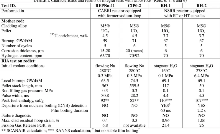
TABLE I. Characteristics and results of integral tests with M5® rods (Refs. 6, 7, 8 and 9)
Test ID. REPNa-11 CIP0-2 RH-1 RH-2
Performed in CABRI reactor equipped
with former sodium-loop
NSRR reactor equipped with RT or HT capsules Mother rod: Cladding alloy Pellet 235U enrichment, wt% Burnup, GWd/tM Number of cycles Corrosion thickness, µm Hydrogen content, ppm M5® UO2 4.5 59 5 15-20 65/70 M5® UO2 4.5 71 6 20 (mean) 70/92 M5® UO2 3.7 67 5 6 70 M5® UO2 3.7 67 5 6 70
RIA test on rodlet:
Initial coolant conditions
Local burnup, GWd/tM Pellet stack length, mm Rod filling gas pressure, MPa Pulse width, ms
Peak fuel enthalpy, cal/g
Departure from nucleate boiling (DNB) detection Film boiling duration Failure diagnosis
Max. clad residual hoop strain, % Fission Gas Release FGR, %
flowing Na 280°C 0.3 MPa 63.5 563 0.3 30.8 92** NO NO 0.4 6.8 flowing Na 280°C 0.3 MPa 74.5 559.5 0.3 28.2 82** NO NO 0.3 not available stagnant H2O 16°C 0.1 MPa 69.1 117 0.1 4.4 110*** YES‡ 60 ms NO 0.96 21.4 stagnant H2O 278°C 6.4 MPa 69.1 50 0.1 4.5 107*** YES 2.2 s NO 1.06 26 ** SCANAIR calculation; *** RANNS calculation; ‡ but no stable film boiling7
RT: Room Temperature; HT: High Temperature
In this paper, ALCYONE V1.4 RIA-related features and [UO2-M5®]-oriented specific modeling are presented first.
integral tests are then shown and compared to relevant available experimental results with a view to the validation of this modeling. Interestingly, this set of four tests allows to study the differences related to the coolant type, its initial temperature and the pulse width.
II.ALCYONE V1.4 RIA-RELATED FEATURES II.A.Main modeling assumptions and capabilities
As regards material behavior modeling and laws, ALCYONE code modeling incorporates in particular fuel pellet creep and cracking (along with dish filling) and, as regards the cladding, gives the possibility to account for, alternatively or in combination when relevant:
• some temperature and flux-dependent yield stress models such as the one available for irradiated Zy4 (Ref. 10) derived from the PROMETRA program (Refs. 11, 12, 13) dedicated to the study of zirconium alloys under RIA loading conditions,
• some high temperature creep models such as the one derived from the database of EDGAR tests (Ref. 14) for M5® under LOCA conditions, which contribution is activated beyond a limit temperature.
Most of models in ALCYONE code are implemented using the open source MFront code generator developed by the CEA in the framework of the mechanical behaviors and material knowledge management strategy of the PLEIADES platform.15 MFront provides a set of domain specific languages handling material properties, mechanical behaviors and simple material models.
The ALCYONE fission gas model CARACAS (Ref. 16) deals with the fission gas creation and evolution at the grain scale. ALCYONE pulse-irradiation simulations clearly take advantage of starting from base irradiation conditions this code itself computes. With no need for any user-dependent specific initialization of the variables prior to pulse-irradiation simulations, the precise and relevant knowledge of the initial fuel rod state and spatial distribution – inter- or intragranular, in bubbles or dissolved – of fission gases is automatically ensured. Nevertheless, being not relevant for RIA conditions yet, the fission gas model calculates a negligible FGR contrary to experimental evidence.
ALCYONE pulse-irradiation simulation capability is based upon:
• the solving of the thermal heat balance equation for the pellet-gap-cladding system in non steady state conditions, • the solving of the thermal and mass balance equations for sodium coolant in non steady state conditions,
• the same for water coolant,
• the incorporation of a material law describing the non linear mechanical behavior of irradiated M5® submitted to RIA loading conditions,
• the addition, to fuel pellet creep and cracking, of grain boundary cracking modeling,
• the use of a specific hypothesis as regards the release of fission gases of the High Burnup Structure (HBS) zone. The first two points have been detailed elsewhere.1 Last four points are discussed hereafter.
II.B.Recent developments
II.B.1.Non steady water heat and mass transport
Solving the heat and mass balance equations requires the estimation of the linear heat rate received by the water coolant from the fuel rod, based upon the heat exchange between the cladding outer surface and the water which involves the clad-to-water coolant heat transfer coefficient (HTC) in particular. The HTC is either given together with the coolant bulk temperature or calculated using ALCYONE built-in thermal hydraulics models.17
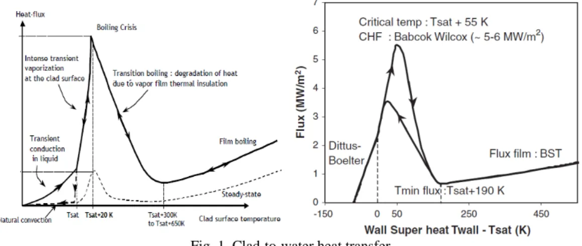
The HTC calculation is based upon the water physical properties issued from the CATHARE thermal hydraulics system code18 developed by the CEA, and clad-to-coolant heat flux derived from correlations for different regions of the boiling curve (i.e. heat flux versus clad temperature) as proposed and described in Refs 19 and 20 for PWR (150 bar, 280°C, 4 m/s) and NSRR (1 bar, room temperature, stagnant liquid water) conditions respectively. The influence thereupon of the high heating rate involved in RIA is taken into account, which renders the heat flux somewhat different from the one in
steady-state cases by impacting how boiling can develop and evolve along the clad (as shown on figure 1-left). The transient boiling curve based on PWR correlations is illustrated on figure 1-right.
Fig. 1. Clad-to-water heat transfer
left: phenomenology in RIA and steady state conditions respectively (from Ref. 21) right: modeling adopted in ALCYONE – PWR case (from Ref. 19)
The correlations for stagnant liquid water conditions were derived by Bessiron from inverse analyses of NSRR tests with the SCANAIR code.20 The transient boiling curve includes four different regimes:
• heat conduction in the stagnant liquid water up to the critical temperature (Tsat + 20 K),
• vaporization of a 30 µm thick layer of water at constant temperature (Tsat + 20 K). This semi-empirical model was introduced to account for the impact of the energy deposition rate on the CHF,
• transition and film boiling regime are simulated with a heat transfer coefficient that decreases exponentially with the clad temperature up to Tsat + 450 K and then asymptotically tends to the film boiling heat transfer coefficient estimated by Sakurai,
• the rewetting phase is activated when the temperature of the minimum heat flux is reached (Tsat + 450 K). The heat flux is calculated according to the same three previous correlations.
In practice, the heat flux derived from the different correlations is prescribed in the thermal calculation. An explicit time integration scheme is used with a strong constraint on the time step, in particular when the CHF is reached.
These developments have been tested successfully during the recent NEA RIA benchmark Phase II.22
II.B.2.A suitable constitutive law for M5®
Loading conditions during a RIA are quite peculiar, especially in terms of clad temperature and strain rates. A suitable constitutive law developed for M5® (see formulation in Ref. 23), supplementing the one already available for irradiated Zy4 (Ref. 10) and applicable to fast transient conditions and high temperatures representative of RIA spectrum, has been incorporated in ALCYONE. More precisely, this constitutive law aims at describing the anisotropic mechanical behavior of the irradiated M5® (fluence from 23.1024 n.m-2 up to 150.1024 n.m-2, i.e. 1 to 6 annual cycles) within large temperature (from 280°C up to 820°C) and strain rate ranges (from 3.10-6 s-1 to 5 s-1). It basically consists in a unified viscoplastic formulation (only one type of inelastic deformation) with no stress threshold between the elastic and viscoplastic regimes. The texture-induced plastic anisotropy of M5® is described by a Hill’s quadratic criterion
σ σ
σ = : M: (1)
where the equivalent stress σ is linked with the stress tensor σ via the Hill’s tensor M .
= ( , ) 1 ) , ( ). , ( φ φ φ σ εvp nT mT p T K & (2) where
m is a parameter describing the strain rate sensitivity, K is the strength coefficient (independent on p), n is the strain hardening exponent,
T and φ denote the temperature and the fluence respectively.
The Hill’s coefficients were identified on the basis of test results available for recrystallized Zy4. The m, K and n parameters were adjusted on a database of around 40 laboratory test results (hoop tensile tests mainly, a few axial tensile tests and closed-end internal pressurization tests) mainly obtained from the PROMETRA program.11,12,13 The model is able to account precisely for the impact of temperature, strain rate, and irradiation damage on the ultimate stress, on the strain hardening exponent (up to uniform elongation) and on the plastic anisotropy of the material. It is suitable for simulations of unfailed UO2-M5® rods.
The assumed isotropic elastic deformation is described by Hooke’s law assuming a temperature-dependent Young’s modulus.
II.B.3.A suitable constitutive law for the UO2 fuel
The model proposed by Salvo24,25 to describe the behavior of uranium dioxide within a range of temperatures (1100– 1700 °C) and strain rates (10-4–10-1/s) representative of RIA loading conditions was implemented in the ALCYONE code. This model consists of a hyperbolic sine model for the creep strain rate with a clear dependency on porosity, completed by a Drucker–Prager yield criterion with associated plastic flow to account for the porosity increase induced by grain boundary cracking. The yield criterion is a temperature-dependent function identified from the compression tests performed at high strain rates and high temperatures that showed significant development of grain boundary cracking. In this case, the samples’ porosity and diameter were found to increase significantly showing that grain boundary cracking proceeds with pore volume increase. The latter is described in the model by the so-called “plastic” porosity.
The creep and grain boundary cracking models are completed by a smeared crack model to describe pellet cracking in tension. The resulting constitutive law is particularly relevant for RIA loading conditions where biaxial compression and tensile stress states are commonly encountered.
II.C.Ongoing improvement related to grain boundary cracking and FGR
As stated earlier, the fission gas model used in ALCYONE (CARACAS, Ref. 16) is so far not able to reproduce the FGR under RIA conditions. As this phenomenon has been evidenced as able, especially for high burnup fuels, to contribute to clad straining during RIAs26,27, in particular through rod internal pressure increase potentially leading to clad ballooning, ALCYONE related improvement is underway. It aims at relating the FGR to grain boundary cracking and thus to the local mechanical damage of the oxide fuel generated by excessive compressive stresses.
This coupling is based upon following assumptions:
• Grain boundary cracking in the calculation is associated to the Drucker–Prager yield criterion mentioned in section II.B.3. When the associated plastic porosity exceeds a given threshold, the grain boundary is considered open. This information is then used by the fission gas model CARACAS to release instantaneously all the intergranular gas (i.e. at the grain boundaries) contained in the fuel pellet rings where the criterion is met.
• In case of high burnup fuel where a HBS (characterized by an extremely fine grained structure and an increased quantity of gases at the grain boundaries) has developed during nominal irradiation in the peripheral regions of the pellet, a temperature threshold is added to the mechanical criterion to be consistent with annealing tests which showed FGR from the HBS at temperatures as low as 900 K (Ref. 28). In case the temperature threshold is reached, all the fission gas content of the HBS (inter- and intragranular gas) is released instantaneously. The gas contained in the grains (i.e. intragranular) of the HBS is assumed to be released instantaneously because the grain size is too small for diffusion to be rate-limiting.
• The plastic porosity which models the dilatancy induced by grain boundary cracking is added to the strains in the thermo-mechanical computation scheme of ALCYONE and contributes therefore to the clad loading.
As stated in Ref. 25, the parameters of the grain boundary cracking model have so far been identified on few tests and their values cannot be considered as definite. Nevertheless, the proposed coupling approach takes advantage of its simplicity, based on only three parameters with a sound physical meaning: a grain boundary opening criterion which triggers intergranular FGR and can be deduced from Vickers indentation tests, a temperature criterion for the release of all the gas inventory from the HBS that comes from annealing test results, a dilatancy associated to grain boundary cracking which might be identified from porosity measurements.
The application of this approach to the UO2-M5® tests considered so far in this paper is shown below (cf. section III.C).
It aims at illustrating how well the discrepancies in terms of grain boundary cracking-induced FGR and clad deformation are simulated.
III.ALCYONE V1.4 SIMULATIONS OF THE CABRI AND NSRR TESTS ON UO2-M5® FUEL RODLETS – SELECTED RESULTS AND DISCUSSION
The CABRI REPNa-11 and CIP0-2 tests and the NSRR RH-1 and RH-2 tests were performed on reconditioned rodlets from full-length commercial UO2-M5® fuel rods (with very high burnup fuel in the CIP0-2 test case). The main
characteristics of these tests are recalled in table I.
A preliminary 1.5D simulation of the respective mother rods base irradiation prior to each one of these pulse tests was first performed with ALCYONE. And then came the simulation of the pulse tests, still with ALCYONE, the fuel column of each rodlet being simulated with ten axial slices of equal height. Unless otherwise stated, the results presented in the following figures are relative to the slice situated at the maximum linear heat rate.
Despite having no detailed data and information about the power history and axial profile of the RH-1 and RH-2 tests, some virtual cases have been shaped as follows with a view to nonetheless proceeding to simulations of (pseudo)RH-1 and (pseudo)RH-2 tests:
• the first four cycles of the base irradiation history of the CABRI CIP0-2 mother rod have been considered consistently with the 67 GWd/t burnup reached prior RH-1 and RH-2 tests;
• it has furthermore been taken profit from similarities between RH-1/RH-2 tests characteristics and those, detailed, of VA-1/VA-3 tests which were available among the specifications of the 2013 phase I NEA benchmark29;
• as the linear power is almost uniform along the pellet stack and the coolant is stagnant, the one-slice approximation was finally adopted in the ALCYONE analysis.
All these assumptions are to be kept in mind during the analysis of the results.
The selected 1.5D and 2D simulation results presented hereafter are mainly discussed in view of the variability these four tests present between one another pertaining to the pulse width (slow or fast pulse) and the test coolant initial temperature (RT or HT).
III.A. Coolant and outer clad surface maximum temperature
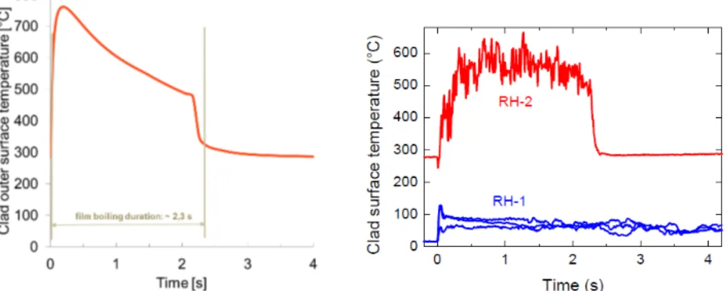
The instrumentation device of the CABRI and the NSRR tests included thermocouples (TC) placed at several axial and azimuthal locations which were used to assess the quality of the heat radial and axial transfer in the fuel pellet - cladding - coolant system. Data of measured outer clad surface temperature are provided in Refs. 7 and 21. As shown on figure 2, the coolant (REPNa-11 and CIP0-2, at 3 TC axial levels) or outer clad surface (RH-1 and RH-2) maximum temperature and its time of occurrence during the pulse are quite well reproduced by ALCYONE. The discrepancy on (pseudo)RH-2 case is obviously related to the outer clad surface temperature being badly measured during the film boiling due to some thermocouple fin effect. In particular, the temperature drop due to heat conduction along the thermocouple wire in the measurement of cladding surface maximum temperature has been shown to reach 200 – 300 K (Refs. 30 and 31). Therefore the measured clad surface maximum temperature and its occurrence time would not be representative of the pulse, explaining the difference calculation versus measurement shown on figure 3. The ALCYONE result compares well with the SCANAIR calculated one (978 K at 0.2 s).21 The boiling phase and rewetting are furthermore well simulated with a film boiling duration of 2.3 s fully consistent with the measured one (cf. figure 3).
Fig. 2. Calculated versus measured value of
left: maximum sodium (CABRI) or outer clad surface (NSRR) temperature ; right: occurrence time of this maximum
Fig. 3. (pseudo)RH-2 case – Clad outer surface temperature evolution with time left: ALCYONE-calculation result; right: measurement (from Ref. 7)
III.B.Temperature and stress radial profiles in the fuel pellet
Figure 4 shows the fuel pellet temperature radial profile evolution during the pulse-irradiation for the four pulse tests considered. Radial profiles are plotted at following times: (t1) before the beginning of the pulse; (t2) during the power rise; (t3) at peak power; (t4) during the power descent; (t5) at the end of the power descent; (t6) after the pulse, just before return to cold state ; (t7) last calculation time step.
Commonly, during the whole short transient power period, the fuel temperature increases in a quasi-adiabatic way resulting in an almost flat radial profile with a maximum localized in an outer ring close to the pellet periphery, consistently with the plutonium content radial distribution. The closer to the end of this period, the higher the mean temperature and the larger the outer ring. The temperature at the fuel pellet centerline typically increases by about 1200 K. Then heat exchanges between the fuel rod and the coolant take place leading to a parabolic temperature profile in the fuel pellet.
The lower the coolant initial temperature (and the higher the ALCYONE calculated energy deposition), the higher the maximum temperature achieved in the pellet and the sharper the temperature profile near the pellet periphery. As expected, a slower pulse with a similar energy deposition, as in the case in ALCYONE calculations of REPNa-11 versus (pseudo)RH-2, leads to a quasi-disappearance of the peripheral temperature peak.
Fig. 4. (Peak Power axial Level PPL) Temperature radial profile evolution during pulse-irradiation above: illustration of the plotting times considered
top left: CIP0-2 case; top right: REPNa-11 case; bottom left: (pseudo)RH-1 case; bottom right: (pseudo)RH-2 Figure 5 shows the fuel pellet axial and circumferential stress radial profile evolution during the pulse-irradiation for the four pulse tests considered. Radial profiles are plotted at the same abovementioned times as for the temperature profiles. The pulse power-induced sharp temperature rise in the outer ring of the pellet generates thermal stress that puts it in a markedly bi-axial (along axial and circumferential directions) compressive stress state, as illustrated on figure 5, with maximum stress level in the [-500 MPa; -350 MPa] range. While decreasing, the compressive stress state progressively spreads radially towards the pellet center.
Fig. 5. Stress radial profile evolution during pulse-irradiation
left: axial stress; right: circumferential stress
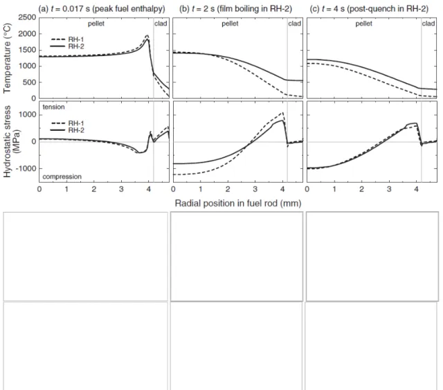
Some code-to-code comparison between RANNS and ALCYONE-calculation results is illustrated on figure 6 for both RH-1 and RH-2 cases on the basis of RANNS results reported by Sugiyama.7 ALCYONE results are here limited to the fuel pellet.
Fig. 6. RH-1 and RH-2 cases – Comparison of radial profile evolution during pulse-irradiation of the temperature and the hydrostatic stress: (top two lines) RANNS results (Ref.7), (bottom two lines) present ALCYONE results
As regards temperature, ALCYONE results are globally similar to RANNS ones, even if the RH-1 centerline temperature is somewhat lower in ALCYONE calculation. As regards the hydrostatic stress, discrepancies are not surprising as the RANNS calculation did not assume pellet crack generation whereas the ALCYONE calculation does. Compressive stresses are thus relaxed so that the minimal hydrostatic stress at the pellet periphery may remain balanced.
III.C.Zones of grain boundary cracking and FGR
Figure 7 shows the radial profile evolution with time over the pulse-irradiation of the plastic porosity (with the threshold mentioned in section II.C upon which exceedance the grain boundary is considered open). Figure 8 shows a synthesis before/after pulse-irradiation of calculated gas-related quantities. Lastly, figure 9 evidences the intergranular gas and gas release fraction kinetics versus the pulse time evolution.
Fig. 7. Plastic porosity radial profile evolution during pulse-irradiation
top left: CIP0-2 case; top right: REPNa-11 case; bottom left: (pseudo)RH-1 case; bottom right: (pseudo)RH-2 The plastic porosity level in the pellet outer periphery clearly depends on whether the pulse is slow or fast. The lower the pulse initial temperature, the more extended the inward radial progression of the plastic porosity in the pellet and the higher its maximum level. Globally no grain boundary opening is predicted for slow pulses: even if the quite high temperature level inside the pellet allows the inward radial progression of the plastification (and the maximum inward radial progression at the end of the pulse may be similar between slow and fast pulses in case of similar injected energy), the latter remains at a too low level to trigger any grain boundary cracking. The modeling thus reproduces the fact that the grain boundary cracking does not solely depend on the burnup and consequently the grain boundary gas content. The plastic porosity localisation does match the experimental area where grain boundaries decohesion was detected through posttest examinations (in fact no decohesion in CIP0-2 and REPNa-11 case; cf. observation results of RH-1 and RH-2 rod circular cross sections reported in Ref. 7).
Fig. 8. Gas concentration radial profile evolution during pulse-irradiation left: before pulse; right: after pulse
Fig. 9. Power, intergranular gas fraction and gas release fraction time evolution
top left: CIP0-2 case; top right: REPNa-11 case; bottom left: (pseudo)RH-1 case; bottom right: (pseudo)RH-2 FGR occurs only in the outmost zone of the pellet (r/r0 > 55%), during the transient power period and not solely after the pulse peak. It is completed before the end of the pulse itself and is mainly composed of intergranular gas.
III.D.Further discussion
This discussion on FGR and clad deformation is largely driven by related considerations by Sugiyama and Georgenthum.7,21 Key elements of their analyses are recalled as a preamble and then discussed in the light of the present results synthetized on figure 10. The maximum clad residual hoop strains plotted here are ALCYONE 2D-calculation results at mid-pellet level (the reference length is the pre-test cladding diameter and not the as-manufactured one).
III.D.1.Discussion on FGR
Sugiyama statements7 – Trying to explain the enhanced release in the RH-2 test versus the RH-1 one, Sugiyama emitted
several assumptions. Having no consistent explanation related to the stress state in the pellet outer region, he suggested the higher gas release fraction in the test RH-2 could be explained by the weaker compressive stress at the pellet center, which could allow thermal expansion of the inter- and intragranular gas bubbles when the center temperature was high, should there be proved that new linkages of the gas release paths at the pellet center during the film boiling be created. Some complementary assumption related to the end pellets highly fragmented state evidenced by radiographs reported in Ref. 7 has been emitted.
Fig. 10. Calculated versus measured values of the: left: FGR; right: maximum clad residual hoop strain
With the present approach, not based on any thermal expansion of the gas bubbles assumption, the discrepancy among the pulses is well reproduced. The FGR of 6.8% measured for REPNa-11 seems low when compared to 8.3% measured for REPNa-4.4 Both tests are indeed slow pulses with similar high burnup ([31 ms | 60 GWd/t] for REPNa-11 case versus [76 ms | 62 GWd/t] for REPNa-4) and the REPNa-4 measured value is quite consistent with the posttest examinations of the rim structure and the REPNa-4 value (7.5%) calculated with the proposed approach. The FGR of 17.5% calculated for (pseudo)RH-2 is quite consistent with the measured one (15%) for the REPNa-5 pulse test.1 Both tests are indeed fast pulses with similar burnup and injected energy levels ([4.4 ms | 67 GWd/t | ~110 cal/g] for (pseudo)RH-2 case versus [9.5 ms | 64.4 GWd/t | 105 cal/g] for REPNa-5). Not to mention that the coupling parameters still need to be finely fitted (cf. section II.C), the underestimation of high FGR is however noticeable and may have two origins. The first one could be the fragmentation state of end pellets as suggested by Sugiyama and the ALCYONE-calculated FGR simply corrected as follows: assuming these end pellets would have released all their intergranular gas (amounting to 21%) and the intragranular gas of the around 305 µm-thick rim zone (amounting to 4.1%), and all other pellets (12 and 2 for (pseudo)RH-1 and (pseudo)RH-2 respectively) would each contribute with the ALCYONE-calculated FGR, the ratio of the average of the total gas release weighted by the number of pellets would be closer to the ratio between the measured values (19.1/21.2 versus 21.4/26). The second origin may be sought in some uncertainty in the base irradiation power level which could have a significant effect on the calculated before pulse initial gas balance.32
III.D.2.Discussion on clad residual deformation
Sugiyama and Georgenthum statements7,21 – In the RH-2 case, almost all the permanent hoop strain of the cladding was
predicted to occur by PCMI, i.e. predominated by the fuel solid thermal expansion, the gas-induced cladding deformation being negligible owing to too low the rod internal pressure level related to the measured FGR (26%).
With the present approach, the calculated values are in quite good agreement with experimental results and taking account of the grain boundary cracking-induced swelling allows a better prediction of the maximum residual clad hoop strain. The grain boundary cracking-induced swelling may clearly be a relevant driving force for the clad strain in addition to the PCMI due to the fuel solid thermal expansion. The underestimation (by around 0.3%) of higher hoop strains is however noticeable. As regards (pseudo)RH-2 specifically, given the computed thermal conditions of the cladding as shown in figure 3, taking legitimately account of high temperature creep of the clad material did not help to reduce it. It may have two origins. The first one might be here again the current lack of fine fitting of the coupling parameters. The second one might be sought in experimental posttest results reported in Ref. 7: experimental barrel-shaped posttest profiles of the fuel pellets were obtained where the barrel-shaped effect resulted in a maximum discrepancy of about absolute 0.4% between residual hoop
strain at mid- and inter-pellet level respectively. Indeed, ALCYONE 1D modeling deals with mean-pellet level intermediary between mid- and inter-pellet one.
A 3D multi-pellet scheme-based17 ALCYONE calculation is pending which may help to analyze the origin of the rather severe fragmentation of the RH-1 and RH-2 end pellets and to quantify the induced FGR. This additional release could increase the rod internal pressure to a level and local conditions that, together with local hot spots (where the critical heat flux is reached), might be conducive to higher clad straining and ballooning.
IV.CONCLUSIONS
In this paper, some 1.5D (and 2D) ALCYONE simulations of RIA transients performed on UO2-M5® fuel rods in
flowing sodium or stagnant water coolant conditions have been compared to the relevant experimental results gained from REPNa-11 / CIP0-2 and RH-1 / RH-2 tests performed in respectively the French CABRI and the Japanese NSRR facilities. The recent and ongoing developments of ALCYONE for RIA conditions aiming at handling both the PCMI first stage and the second stage, should the boiling crisis occur, of the transient have first been briefly described, including the integration of suitable constitutive models for irradiated M5® and UO2 as well as the coupling between the grain boundary cracking and
FGR and clad deformation. The discussion of the results presented evidenced in particular the impact of the pulse width and the initial coolant temperature. With the proposed approach adopted in ALCYONE code, which differs from RANNS and SCANAIR ones, the discrepancy among the pulses is well reproduced in terms of both FGR which kinetics can furthermore be grasped and clad hoop strain even if some further improvement is needed in this latter case. The grain boundary cracking-induced swelling may clearly be a relevant driving force for the clad strain in addition to the PCMI due to the fuel solid thermal expansion.
With a view to simulating and analyzing further tests to be performed under prototypical PWR conditions within the CABRI International Program with the ALCYONE code, some further work and improvement is required first as regards the proposed modeling of grain boundary cracking and coupling with FGR and clad deformation: the parameters need to be refined for UO2 fuel and the approach is to be adapted to MOX fuel. Furthermore, the development of gas axial flow
modeling has been undertaken with a view to especially calculating whole PWR rods and not only reconditioned rodlets. In parallel, uncertainty analysis capabilities shall be improved and based upon towards a comprehensive work.
ACKNOWLEDGMENTS
The authors would like to thank AREVA and EDF for the financial and technical support to this work.
REFERENCES
1. J. SERCOMBE et al., “1D and 3D modeling of PCMI during a RIA with ALCYONE V1.1”, Proc. of TopFuel
Conference, Orlando, Florida, USA (2010).
2. B. MICHEL et al., “Modeling of pellet cladding interaction”, in: Compr. Nucl. Mater., pp. 677-712, R. KONINGS, Ed, Elsevier Ltd (2012).
3. J. SERCOMBE et al., “2D simulation of hydride blister cracking during a RIA transient with the fuel code ALCYONE”,
EPJ Nuclear Sci. Technol., 2, 22 (2016).
4. “Nuclear fuel behaviour under reactivity-initiated accident (RIA) conditions: state-of-the-art report”, NEA/CSNI/R(2010)1, Nuclear Energy Agency, Organisation for Economic Co-operation and Development (2010). 5. V. GARAT et al., “M5® fulfills the new requirements by regulators”, Proc. of TopFuel Conference, Charlotte, North
Carolina, USA (2013).
6. J. PAPIN et al., “IRSN R&D studies on high burn-up fuel behaviour under RIA and LOCA conditions”, Proc. of
TopFuel Conference, Salamanca, Spain (2006).
7. T. SUGIYAMA et al., “Evaluation of initial temperature effect on transient fuel behavior under simulated reactivity-initiated accident conditions”, J. Nucl. Sci. Technol., 47[5], 439 (2010).
8. J. PAPIN et al., “Summary and interpretation of the CABRI REP-Na program”, Nucl. Technol., 157, 230 (2007).
9. T. SUGIYAMA et al., “Applicability of NSRR room/high temperature test results to fuel safety evaluation under power reactor conditions”, Proc. of Nuclear Fuel Behavior during Reactivity Initiated Accidents, Paris, France (2009), NEA/CSNI/R(2010)1, Nuclear Energy Agency, Organisation for Economic Co-operation and Development (2010).
10. M. LE SAUX et al., “A model to describe the anisotropic viscoplastic mechanical behavior of fresh and irradiated Zircaloy-4 fuel claddings under RIA loading conditions”, J. Nucl. Mater., 378, 60 (2008).
11. B. CAZALIS et al., “The PROMETRA program: Fuel cladding mechanical behavior under high strain rate”, Nucl.
Technol., 157, 215 (2007).
12. B. CAZALIS et al., “The PROMETRA program: a reliable material database for highly irradiated zircaloy-4, ZIRLOTM and M5TM fuel claddings”, Proc. of International Conference on Structural Mechanics in Reactor Technology (SMiRT), Beijing, China (2005).
13. B. CAZALIS et al., “The PROMETRA Program: Plane Strain Tests on Fresh and Highly Irradiated Zircaloy-4, ZIRLO® and M5TM Fuel Claddings”, Proc. of Water Reactor Fuel Performance Meeting/TopFuel Conference, Boise, Idaho, USA (2016).
14. T. FORGERON et al., “Experiment and modeling of advanced fuel rod cladding behavior under LOCA conditions: alpha/beta phase transformation kinetics and EDGAR methodology”, in: Zirconium in the nuclear industry: Twelfth
International Symposium. ASTM STP 1354, Toronto, Canada (1998).
15. T. HELFER et al., “Introducing the open-source mfront code generator: Application to mechanical behaviours and material knowledge management within the PLEIADES fuel element modelling platform”, Comput. Math. Appl., 70, 994 (2015).
16. G. JOMARD et al., “CARACAS: An industrial model for description of fission gas behavior in LWR-UO2 fuel”, Proc. of
Water Reactor Fuel Performance Meeting/TopFuel Conference, Sendai, Japan (2014).
17. P. GOLDBRONN et al., “Avancées de la simulation du comportement du combustible nucléaire en 3D et en transitoire rapide ”, Congrès français de mécanique, Bordeaux, France (2013).
18. G. GEFFRAYE et al., “CATHARE 2 V2.5.2: A single version for various applications”, Nucl. Eng. Des., 241, 4456 (2011).
19. V. BESSIRON, “Modelling of clad-to-coolant heat transfer for RIA applications”, J. Nucl. Sci. Technol., 44[2], 211 (2007).
20. V. BESSIRON et al., “Clad-to-coolant heat transfer in NSRR experiments”, J. Nucl. Sci. Technol., 44[2], 723 (2007). 21. V. GEORGENTHUM, T. SUGIYAMA, “Influence of initial conditions on rod behavior during boiling crisis phase
following a reactivity initiated accident”, Proc. of Nuclear Fuel Behavior during Reactivity Initiated Accidents, Paris, France (2009).
22. NEA/CSNI/R(2010)1, Nuclear Energy Agency, Organisation for Economic Co-operation and Development (2010). “Reactivity initiated accident (RIA) fuel codes benchmark Phase-II, Report – Volume 1, Simplified cases results, Summary and analysis”, NEA/CSNI/R(2016)6/VOL1, Nuclear Energy Agency, Organisation for Economic Co-operation and Development (2016).
23. A. MOAL et al., “SCANAIR: a transient fuel performance code – part one: general modelling description”, Nucl. Eng.
Des., 280, 150 (2014).
24. M. SALVO et al., “Experimental characterization and modeling of UO2 behavior at high temperatures and high strain rates”, J. Nucl. Mater., 456, 54 (2015).
25. M. SALVO et al., “Experimental characterization and modeling of UO2 grain boundary cracking at high temperatures and high strain rates”, J. Nucl. Mater., 460, 184 (2015).
26. J. PAPIN et al., “Main outcomes from the CABRI test results”, NEA CSNI topical meeting on RIA fuel safety criteria, Aix-en-Provence, France (2002), OECD Nuclear Energy Agency, NEA/CSNI/R(2003)8, Vol.2, 61-81, (2003).
27. F. LEMOINE, “High burnup fuel behavior related to fission gas effects under reactivity initiated accidents (RIA) conditions”, J. Nucl. Mater., 248, 238 (1997).
28. J.-P. HIERNAUT et al., “Fission product release and microstructure changes during laboratory annealing of a very high burn-up fuel specimen”, J. Nucl. Mater., 377, 313 (2008).
29. “RIA fuel codes benchmark – Volume 1”, NEA/CSNI/R(2013)7, Nuclear Energy Agency, Organisation for Economic Co-operation and Development (2013).
30. T. TSURUTA, T. FUJISHIRO, “Evaluation of thermocouple fin effect in cladding surface temperature measurement during film boiling”, J. Nucl. Sci. Technol., 21[7], 515 (1984).
31. P. RUYER, “Clad to coolant heat transfer during RIA in PWR conditions”, Proc. of Water Reactor Fuel Performance
Meeting/TopFuel Conference, Boise, Idaho, USA (2016).
32. A. BOULORÉ, Pending communication, UAM-11 Workshop, Nuclear Energy Agency, Organisation for Economic Co-operation and Development, Erlangen, Germany (2017).