HAL Id: cea-02457110
https://hal-cea.archives-ouvertes.fr/cea-02457110
Submitted on 27 Jan 2020
HAL is a multi-disciplinary open access
archive for the deposit and dissemination of
sci-entific research documents, whether they are
pub-lished or not. The documents may come from
teaching and research institutions in France or
abroad, or from public or private research centers.
L’archive ouverte pluridisciplinaire HAL, est
destinée au dépôt et à la diffusion de documents
scientifiques de niveau recherche, publiés ou non,
émanant des établissements d’enseignement et de
recherche français ou étrangers, des laboratoires
publics ou privés.
Traveling wave array for DEMO with proof of principle
on WEST
R. Ragona, A. Messiaen, Jean-Michel Bernard, E. Delchambre, R. Dumont, F.
Durodié, Julien Hillairet, J. Ongena, D. van Eester, M. van Schoor
To cite this version:
R. Ragona, A. Messiaen, Jean-Michel Bernard, E. Delchambre, R. Dumont, et al.. Traveling wave
array for DEMO with proof of principle on WEST. Fusion Engineering and Design, Elsevier, 2019,
146, pp.854-857. �10.1016/j.fusengdes.2019.01.097�. �cea-02457110�
_______________________________________________________________________________ author’s email: riccardo.ragona@rma.ac.be
Traveling Wave Array for DEMO with proof of principle on
WEST
R. Ragona
a,b, A. Messiaen
a, JM. Bernard
c, E. Delchambre
c, R. Dumont
c, F. Durodié
a, J. Hillairet
c, J.
Ongena
a, D. Van Eester
a, M. Van Schoor
aaLaboratory for Plasma Physics LPP-ERM/KMS, B-1000 Brussels, Belgium bApplied Physics Department, Ghent University, B-9000 Gent, Belgium
cIRFM, CEA, F-13108 Saint Paul-lez-Durance, France
To decrease the power density and associated high voltages, a distributed antenna system is proposed as ICRH system for the DEMO reactor. Among the different solutions, a layout made from a set of travelling wave array (TWA) sections is considered as the most promising [1, 2]. It optimizes coupling to the plasma, is load resilient and avoids large values for the VSWR in the feeding lines. The total radiated power scales as the number of independently fed sections such that high reliability can be expected. The TWA concept for ICRH is innovative and very different from the traditional IC antennas. A test on WEST should provide a proof of principle of the validity of the TWA approach together with a comparison with the existing WEST IC antennas. The chosen geometry of the TWA section is compatible with one unit of the complete set designed for a future reactor [3].
The paper describes the progress made in the preparation of a test on WEST along with the extrapolation for a future reactor like DEMO. A comparative modeling with the present antennas is also discussed and a preliminary RAMI analysis is introduced showing the promising positive impact of the TWA design on the RAMI scores. Keywords: ICRF, TWA, DEMO, WEST
1. Introduction
An Ion Cyclotron Range of Frequency (ICRF) system can provide power for a number of tasks, experimentally verified on present machines: heating and current drive, first wall conditioning, plasma startup, removing of impurities from the core, controlling sawteeth and current ramp down assist. The system has a high plug-to-power efficiency and most of the components external to the machine are sturdy, with industrial steady state capability. Traditional ICRF antenna systems are often characterized by a high operating voltage and high power density. Low power density and low voltage however provides a bonus in terms of reliability. Therefore, travelling wave type antennas have been proposed [1,2]. They can be integrated in the blanket and use only a limited number of feeders. The k// spectrum is
peaked and the dominant k// value can be optimized for
coupling and bulk absorption, while avoiding the generation of coaxial modes in the edge. Assuming the ITER-2010-low density profile, 50 MW can be easily coupled with a voltage on the antenna components of about 15 kV [3,4].
This contribution briefly describes the progress made in the preparation of a test on the WEST device and a comparative modeling with the present WEST antennas is also discussed. Some preliminary results of a RAMI analysis of the TWA are reported here and extrapolated to the DEMO reactor.
2. Traveling Wave Array system
An ICRF system based on traveling wave arrays is proposed for DEMO [2,3]. It consists of 16 sections of 2 superposed TWA. All sections are independent and toroidally isolated from each other. For this reason, one single section could be tested on WEST giving experimental results that can be extrapolated to the complete DEMO system. It consists of a double poloidal array of 8 straps, as shown in Fig.1. The strap configuration is of the L-type, i.e. grounded at one end. Each array is fed by a resonant ring circuit, as shown in Fig.2. The tuning of the system is made by two actuators
, i.e. line stretchers (LS), labeled LSR (for resonance tuning) and LSC (for coupling tuning). They allow cancelling the power that goes into the dummy load, maximizing the power delivered to the TWA and then radiated to the plasma. Differently from the classical antenna design, the lines used to feed and recirculate the power to/from a TWA are intrinsically matched, thus operated at VSWR = 1. This minimizes the power dissipation and the risks of breakdown.
Fig. 1. A possible configuration for the WEST TWA. It consists of two independent superposed L sections of 8 straps.
Fig. 2.Schematic of one TWA system with the resonant ring feeding circuit made by the LSR line stretcher and the variable coupler made with 2 hybrid (-3 dB) couplers and the line stretcher LSC. All components except the TWA are outside the machine.
The nominal power level for the IC antennas in WEST is 3MW-30s for the high power short pulse scenario and 1MW-1000s for the long pulse “steady state” scenario [5]. Each TWA system is designed to comply with those specifications, i.e. 1.5MW-30s and 500kW-1000s per section. The main limitation to the operation at high power comes from the power limit of the vacuum feedthrough (VF). Experimental tests [6] showed that the installed VF can be safely operated at 1.75MW for 50s before exceeding a critical temperature. In the resonant ring TWA system, part of the power is re-circulated back to the input and summed up with the power launched by the generator. The amount of input power delivered to the TWA, which depends on the coupling to the plasma, should not exceed that critical power level. A first assessment of the coupling property of the TWA system is made with the ANTITER-II code. The model layout is shown in Fig.3 with the relevant dimensions. The density profile in front of the TWA is a WEST profile characterized by a Linear Averaged Density (LAD) of
6x10!" m!![5]. The separatrix/antenna distance is set to
10 cm. At the nominal frequency 𝑓 = 55 MHz, the input power required to couple 500 kW is 𝑃in≈ 570 kW from
which 70 kW are re-circulated. When the power is raised up to 1.5 MW, 𝑃in≈ 1.71 MW with a re-circulated
fraction of approximately 210 kW. Those input powers do not exceed the limits imposed by the VF and by the transmission lines [5,6]. Moreover, the considered profile represents a low coupling case. If the linear average density is increased or if the separatrix/antenna distance is decreased, the input power will decrease, remaining safely under the limits. An evaluation of the corresponding strap voltages for the two power cases is presented in Fig. 4. The two sections are displaced poloidally by 13 cm. The coupling between the two sections is evaluated by a new feature of the ANTITER-II code [7] and it is shown in Fig.5 where the imaginary part of the full-system impedance matrix is presented. The elements on the main diagonal are the self-impedance of each strap. The matrix is formed by four 8x8 sub-matrices. The two on the main diagonal
correspond to the individual sections while the two on the anti-diagonal represent the mutual coupling between the two sections. In-phase operation presents no problem of inter-coupling between the generators and it is considered as reference configuration. A more detailed analysis of the effect of the coupling will be published elsewhere.
Fig. 3. Double TWA layout, as in Fig.1. Dimensions in mm.
Fig. 4. Strap voltage for the TWA sections at the two nominal
power levels: 3MW-30s and 1MW-1000s. The plasma profile
is characterized by a Linear Averaged Density (LAD) of
6x10!" m!! and 10 cm separatrix/antenna distance.
Fig. 5. Imaginary part of the arrays impedance matrix. The two TWA sections are coupled together as shown by the antidiagonal submatrices.
The TWA system is compared to the classical antenna already installed in WEST evaluating the power absorption in the plasma by means of the EVE code[ref]The scenario used is minority heating D(H)5% [8]
with the density and temperature profile described in the previous section. The results show the fundamentally different behavior of the two designs. The TWA concentrates more power into desired toroidal number while the response of the classical antenna is broader. This is shown in Fig.6 where the spectra of the two designs are compared.
Fig. 6. Spectra computed by the EVE code for the TWA and the classical antenna. The TWA shows a higher directionality.
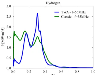
The absorbed power density vs the flux surface labeling parameter is presented in Fig.7. It reveals the impact of the enhanced directionality of the TWA w.r.t. the classic antenna: the power is spread over a less wide region. At 𝑓 = 55MHz, the maximum absorption does not occur in the core (rho=0) but slightly off-axis, more focused around the location of the resonance layer; the spreading in the deposition is due to the Doppler shift caused by the finite temperature and k//. The classical antenna has a
larger spread in k//, which results in a less localized
power deposition.
Fig. 7. Power absorption vs magnetic surface label computed by EVE for the classical antenna compared to the TWA at the nominal frequency 𝑓 = 55MHz.
The 2D power absorption profiles depicted in Fig.8a,b correspond to the curve shown in Fig.7. The broader deposition of the classic antenna occurs between the magnetic axis and the resonance layer while the more localized deposition of the TWA concentrates closer to the resonance layer, an advantage that could be exploited. In case this is needed, to remain in the good confinement region (the width of this region depending on the plasma current) [8], the driver frequency can be adapted slightly. An example of the effect on the power deposition for different frequencies is shown in Fig.9 (lowering the frequency shifts the resonance layer towards the antenna). 𝑓 = 52.5MHz yields a very peaked deposition close to the magnetic axis. The corresponding 2D power absorption is depicted in Fig.8c. This frequency is already in the nominal band of the WEST IC power plant [5] and the hybrid of the resonant ring could be designed to cover a suitable band [9], e.g. 51MHz ÷ 56MHz, allowing different configurations in the experimental phase. The TWA can be easily optimized to have a bandwidth of ~10MHz, covering the above mentioned band.
Fig. 8. (a) 2D power absorption computed by EVE for the classical antenna compared to (b) the TWA at the nominal frequency 𝑓 = 55.5MHz and (c) at the optimized frequency 𝑓 = 52.5MHz.
Fig. 9. Power absorption vs magnetic surface label computed by EVE for the TWA at different frequencies.
4. RAMI analysis
Whereas ITER is primarily a physics device, DEMO is different in that it will be a technology-oriented device that must validate both the technological basis and the economic viability. In that context, availability is a primary measure of the effectiveness; it directly affects the cost of generated electricity. Therefore adopting a Reliability Availability Maintainability and Inspectability (RAMI) approach is of key importance during the engineering design phase of Fusion Power Plant (FPP) sub-systems. A preliminary RAMI analysis is performed for both the classical antenna and a TWA. When projected on long time-scale, the results show that the simplicity of the TWA system allows a better scoring with respect to a classical antenna.
Results show that for the TWA antenna design concept, the functions that need to be fulfilled are within reach using simple transmission lines, no tunable components and no motorization system under vacuum. This reduces significantly the potential anomalies and failures during operation. Moreover, the new design implies mainly out-vessel components (the resonant ring: line stretcher, hybrid couplers and dummy loads) which improve the overall maintainability and inspectability of the system. In a reactor, those components could be placed outside the bioshield in a less critical environment. Taking into account the type and number of components for each design, duty cycle, Mean Time Between Failure, Mean Time To Repair and assuming spares onsite during operation, the expected availability after a year of campaign has been assessed for the main, intermediate and basic functions of both designs. The main function “to provide 3MW of plasma heating” is improved by ~10% with the TWA design in comparison with the current availability calculated on the concept used in the WEST ICRH system. Projected on the long time scale of operation for a reactor, this improvement is significant. Due to lack of space, an extended analysis will be published elsewhere with a detailed description of all the aspects of the RAMI scores for the TWA and its extrapolation to a reactor like DEMO.
5. Summary and conclusions
The preliminary RF design of a TWA system that allows a direct extrapolation to the presented DEMO design is assessed. Two L-type sections, equivalent to a single DEMO sector, can be installed on WEST in replacement of one existing antenna while complying with the ICRF power requirements and limitations. Each of both sections is designed for 1.5MW-30s & 0.5MW-1000s
and the resonant ring is designed not to exceed the vacuum feedthrough power limit of 1.75MW-50s. A power absorption computation showed the more focused deposition around the resonance layer compared to the presently installed antenna. This is due to the TWA’s enhanced directivity. The absorption can be peaked on the magnetic axis when the frequency is moved to 𝑓 = 52.5MHz. This frequency is inside the band of the TWA (centered on 𝑓 = 55MHz and with a bandwidth of ~10MHz). The hybrid, part of the resonant ring, will be adapted to cover the same bandwidth. The mechanical and thermal compatibility of the system are the topic of the next phase of this project. A test of the RF strap configuration at high power is also under preparation. It will exploit the TITAN facility located in CEA-Cadarache [10].
The preliminary RAMI analysis shows a better scoring (10%/year more availability, improved maintainability and inspectability) for the TWA mainly due to the simplicity of its design when compared to the classical one. Regarding in-vessel components, such as strap sections allocated inside the blanket in the case of the TWA, some uncertainties on failure modes, their occurrence and severity remain. For this reason a test in WEST of these components under different plasma conditions is of primarily interests. Moreover, it allows studying their possible maintenance strategy in a FPP such as DEMO. An extended RAMI analysis is strongly recommended in view of the DEMO conceptual design.
References
[1] R. Ragona and A. Messiaen 2017 EPJ Web of Conferences 157, 03033
https://doi.org/10.1051/epjconf/201715703044
[2] A. Messiaen and R. Ragona 2017 EPJ Web of Conferences
157, 03033 https://doi.org/10.1051/epjconf/201715703033
[3] J-M. Noterdaeme et al., Giardini Naxos, Italy, September 16-21. Proceedings of the 30th Symposium on Fusion Technology (SOFT-30) 2019.
[4] A. Messiaen and R. Ragona 2016 43rd EPS conference on Plasma Physics Vol.40A, 4-8 July Leuven BE.
http://ocs.ciemat.es/EPS2016PAP/pdf/P2.066
[5] J.Hillairet et al., 2015 AIP Conference Proceedings 1689, 070005. https://doi.org/10.1063/1.4936512
[6] G. Agarici, CEA internal report CH/NTT-2006.035 [7] A Messiaen and R Ragona 2019 Plasma Phys. Control.
Fusion 61 044004
https://doi.org/10.1088/1361-6587/aaf8bd
[8] C. Bourdelle et al., 2015 Nucl. Fusion 55, 063017
https://doi.org/10.1088/0029-5515/55/6/063017
[9] H. J. Kim et al., 2012 Appl. Phys. Lett. 100, 263506
https://doi.org/10.1063/1.4731241
[10] J.M. Bernard et al., Fus. Eng. and Design 86 (2011) 876–