HAL Id: hal-02932308
https://hal.archives-ouvertes.fr/hal-02932308
Submitted on 7 Sep 2020
HAL is a multi-disciplinary open access
archive for the deposit and dissemination of
sci-entific research documents, whether they are
pub-lished or not. The documents may come from
teaching and research institutions in France or
abroad, or from public or private research centers.
L’archive ouverte pluridisciplinaire HAL, est
destinée au dépôt et à la diffusion de documents
scientifiques de niveau recherche, publiés ou non,
émanant des établissements d’enseignement et de
recherche français ou étrangers, des laboratoires
publics ou privés.
Off-axis parabolas super polished under stress: the case
of the Roman Space Telescope Coronagraphic
instrument mirrors
Melanie Roulet, Emmanuel Hugot, Carolyn Atkins, Michel Marcos, Simona
Lombardo, Anne Bonnefoi, Amandine Caillat, Marc Ferrari
To cite this version:
Melanie Roulet, Emmanuel Hugot, Carolyn Atkins, Michel Marcos, Simona Lombardo, et al.. Off-axis
parabolas super polished under stress: the case of the Roman Space Telescope Coronagraphic
instru-ment mirrors. Optics Express, Optical Society of America - OSA Publishing, 2020. �hal-02932308�
Off-axis parabolas super polished under stress:
the case of the Roman Space Telescope
Coronagraphic instrument mirrors
M
ELANIER
OULET,
1,*E
MMANUELH
UGOT,
1, C
AROLYNA
TKINS2,
M
ICHELM
ARCOS 1, S
IMONAL
OMBARDO 1, A
NNEB
ONNEFOI 1,
A
MANDINEC
AILLAT1, M
ARCF
ERRARI11Aix Marseille Univ, CNRS, CNES, LAM, Marseille, France
2UK Astronomy Technology Centre, Royal Observatory, Edinburgh, EH9 3HJ, UK *melanie.roulet@lam.fr
Abstract:
Direct imaging of exoplanets requires high contrast imaging techniques that demand tight tolerances on the optical surface error. The Nancy Grace Roman Space Telescope (RST) (previously named WFIRST) aims to perform direct imaging of SuperEarth-like exoplanets through its active coronographic instrument (CGI). Eight off-axis parabola (OAP) mirrors are utilised within the CGI to create a compact instrument and to ensure access to the pupil and focal planes. The surface form error and surface roughness of these relay optics directly impact the quality of the dark hole, and therfore the observable location for exoplanets. A new fabrication process for OAP manufacture via stressed mirror polishing (SMP) is presented in this paper. First, the design of the mirror substrate is investigated to create an innovative thickness distribution capable of producing the OAP geometry with a simple warping harness composed by two micrometer screws. Second, the novel design is implemented on a 60 mm diameter OAP prototype in Zerodur; a description of the fabrication process chain and the characterisation of the optical surface over all spatial frequencies are presented. Results from this first prototype demonstrated that the surface form error deviates from < 1 nm root means square (RMS) from the simulations and with a surface roughness of 2.1 ˚𝐴 Ra.
© 2020 Optical Society of America under the terms of theOSA Open Access Publishing Agreement
1. Introduction
1.1. Exoplanet imagery techniques
Earth-like exoplanets detection is one of the key science goals for the next generation of astronomical instrumentation. To distinguish the faint Earth-like planet from its host star requires high contrast imagining and low angular resolution. Since the 1990s, coronagraphic instruments have been combined with Adaptive Optics (AO) system to achieve this sensitivity [1]. Current ground-based systems, such as the Spectro Polarimetric High-Contrast Exoplanet Research SPHERE [2] on the Very Large Telescope VLT and the Planet Imager GPI on the GEMINI telescope [3] can achieve up to 10−6contrast and have demonstrated direct imaging of Jupiter-sized exoplanets.
Looking to the future, the NASA led Nancy Grace Roman Space Telescope (RST), previously named Wide Field Infrared Survey Telescope (WFIRST), will incorporate the first space-based active coronagraphic instrument (CGI) for direct imaging of exoplanets [4]. The CGI will be able to characterise the atmospheres of super-Earth planets and Neptune-like planets around nearby Sun-like stars, reaching detectable planet and star contrast ratios of 10−9, after post-processing at angular separations > 0.2 arcseconds [4].
whereas, the RST AO will correct the fabrication form errors within the optics and drifts incurred by either thermal or dynamic effects [7]. A combination of two deformable mirrors (DM) are utilised to correct both amplitude and phase of the wavefront errors. A dedicated Low Order Wavefront Sensing and Control (LOWFS/C) system, inspired by ground-based instrumentation, corrects the first 11 Zernike modes, which are mainly produced by long duration thermal drifts [8]. Higher order modes, called mid-spatial frequency, are controlled via focal plane wavefront correction with the DMs to create the dark hole and maintain its high-contrast [9]. The high-spatial frequencies are defined outside the correction circle of the AO and are mainly caused by inaccuracies in the coronagraph masks and surface roughness errors on the optics. The Lyot coronagraphic technique used in CGI, is sensitive to the high frequencies overlapping, which directly impacts the dark hole, hiding the faint Earth-like planet signal within the noise. Compensation can be implemented in the focal plane to limit the impact of these quasi-static aberrations, but it is preferable to limit the high frequency errors from the source: during optical fabrication. It has been demonstrated that the point spread function post coronagraphy is equal to the Power Spectral Density (PSD) of the instrument [10]. Therefore minimising PSD of optics is essential to reduce residual speckles in coronagraphic instrument. In this study, the optics are characterised by computing the PSD and are compared to the final image specification.
In the case of the RST CGI, off-axis parabolas (OAPs) have been used within the optical design as relay optics [7], this creates a compact instrument, which fits within a limited space and ensures access to the different pupil and focal planes. The OAPs are not located in the focal plane, thus their surface form errors and roughness cannot be compensated by the DMs, therefore, the OAP optical quality is crucial because it is directly transmitted to the Fourier plane and the error is double due to the reflection.
1.2. OAP fabrication and difficulties
OAPs are challenging to manufacture and measure. Often OAPs are manufactured by creating a large on-axis parabola and cutting out the required optical geometry. This technique requires large machinery for a small work piece, leads to significant waste material, and typically results in low to mid spatial frequency errors [11]. An alternative approach is single point diamond turning (SPDT) with computer numerical control (CNC). This technique requires a complex and very accurate positioning of the OAP with respect to the machine, which is possible via adaptive tools and results in freeform optics that can be manufactured with < 5 nm RMS surface roughness [12]. However, the SPDT approach produces tool marks, ripples, which significantly contribute to the high frequencies errors [13]. In a similar approach, Computer-controlled optical surfacing (CCOS) can be employed that uses an automated arm to move a polishing tool slowly upon the substrate surface [14]. CCOS is suited for large OAP workpieces, as demonstrated by R. Jones et al. (1994) [15] and Kim et al. (2016) [16] by reaching < 1 nm roughness on a large off-axis aspheric mirror. Coupling CCOS with a non-linear fluid and a predictable tool influence function provides similar roughness < 1 nm [17], this method has been applied to the giant magellan telescope (GMT) 8.4 m off-axis primary mirror segments.
Likewise, finishing techniques have been developed to improve the surface quality of these complex shape mirrors. MagnetoRheological Finishing (MRF) shows impressive results by eliminating damage from polishing and can smooth the RMS roughness to < 1 nm [18] [19]. MRF uses a magnetically-stiffened abrasive fluid to remove damage on the surface; however, this process takes a significant duration to converge to the required surface quality. Ion beam figuring (IBF) is another deterministic method, which involves removing matter from optical surface with a stable beam of accelerated particles. Experiments show that this technique can remove surface forms errors while maintaining a very low roughness [20] [21].
1.3. Stress polishing apply to OAP fabrication
An alternative technique for OAP fabrication is Stressed Mirror Polishing (SMP): a process first developed in the 1930s by the German astronomer Bernhard Schmidt [22]. This technique applies a pressure on a mirror substrate during polishing to obtain the desired optical surface figure. Several experiments and prototypes have been undertaken, such as adapting the method using vacuum to apply the pressure to the mirror to create aspherisation plate with single zone method as E. Everhart et al. (1966) [23], or double zone method developed by G. Lemaitre et al. (1972) [24]. Later, the generation of single aberration modes by SMP with a minimum number of actuators is investigated by Lemaitre et al [25] using a novel thickness distribution at the back of the mirror and new pressure devices, such as actuators.
The investigations undertaken by G. Lemaitre have led to the development of toric mirrors at Laboratoire d’Astrophysique de Marseille (LAM) via the SMP method. In this case, forces are applied through a warping harness using only one actuator. The substrate is then polished by hand via spherical polishing and utilising a tool size with the same dimensions as the substrate to minimise surface form errors. The deformation induced by the warping harness is then imprinted upon the surface during polishing. SMP is ideally suited for high contrast imaging, as demonstrated by the three toric mirrors manufactured by LAM for the SPHERE instrument where surface roughness values between 0.2 nm RMS and 0.9 nm RMS were realised [26]. A further example of a LAM SMP toric mirror was for the Hi-CAT project, where the final roughness was <1 nm RMS [27].
To generate an OAP via SMP, Lubliner and Nelson (1980) [28] showed that an OAP geometry can be decomposed using Zernike polynomials and this led to the realisation of the 10 m diameter segmented primary mirror of Keck telescopes. The hexagonal OAP segments, 1.8 m in diameter, were fabricated using SMP by Nelson et al. (1980) [29]; however, twenty-four radial arms were needed to apply the deformation. In this paper, a solution to adapt the LAM toric mirror SMP technique to fabricate the RST OAPs, whilst ensuring simplicity of manufacture, is presented. This paper will outline the OAP SMP methodology and includes: the RST CGI design requirements (Section 2), the warping harness design study to generate the OAP profile (Section 3), and the prototyping phase to validate the OAP warping harness design (Section 4).
2. Concept and requirements
2.1. Requirements
The RST CGI is a Lyot coronagraph composed of eight OAPs; the optical design is presented in Fig. 1. The beam arriving from the telescope, located at FSM in Fig. 1, is relayed and magnified to the two DMs by OAP1 and OAP2. Then OAP3 and OAP4 relay the pupil beam to the reflective masks wheel (SPM). OAP5 focus the light at the focal plane masks (FPM) also mounted on a wheel. The reflected light is then injected to the LOWFS camera, while the transmitted light is collimated on the Lyot stop by OAP6. Then OAP7 focuses the beam on the field stop. Finally OAP8 collimates the light to the pupil plane of the colour filter. The beam finishes its course into the spectograph camera IFScam [30]. Table 1 presents the geometrical specifications of the eight OAPs, including physical diameter, off-axis distance, parent radius and effective focal length.
From the sag of the conic surface, we can compute the asphericity coefficients 𝛼𝑖 , 𝑗 and thus express the sag in its local coordinates (𝜌, 𝜃) [28] [29]. The coefficients lead to the Zernike coefficients and reveal that an OAP is primarily composed of the third order aberrations astigmatism 3x and coma 3x, as shown in Fig. 2. Trefoil 5x and higher terms are negligible in comparison and are not taken into account within the specifications. Using the parameters in Table 1, the Zernike coefficients have been computed for the eight OAPs on their clear aperture (Table 2). The local radius of curvature of the mirror, which is used during the polishing, is defined as twice the effective focal length and termed radius of polishing (RoP).
Fig. 1. Optical design of the RST CGI. Credit: F. Zhao (2017) [30].
Parameters [mm] OAP1 OAP2 OAP3 OAP4 OAP5 OAP6 OAP7 OAP8
Diameter 𝑑 60 60 60 60 60 60 60 30
Off axis distance 160.0 184.1 290.5 106.6 133.0 133.0 152.0 60.1
Parent radius 980.6 1128.3 2399.4 881.0 1080.0 1080.0 1400.0 410.0 Effective focal length 503.3 579.2 1217.3 446.9 548.2 548.2 708.3 211
Table 1. The geometrical OAP requirements for the RST CGI
Fig. 2. Illustration of the OAP shape decomposition into Noll Zernike polynomials. Zernike coefficients OAP1 OAP2 OAP3 OAP4 OAP5 OAP6 OAP7 OAP8 Astig 3x RMS [𝜇m] -1.288 -1.447 -0.381 -0.201 -0.170 -0.170 -0.102 -0.174 Coma 3x RMS [𝜇m] -0.099 -0.110 -0.019 -0.012 -0.008 -0.008 -0.004 -0.007 Trefoil 5x RMS [𝜇m] +0.003 +0.002 0 0 0 0 0 0 Clear aperture [mm] 44 50 50 22 22 22 22 10 RoP [mm] 1006.6 1158.0 2434.6 893.8 1096.4 1096.4 1416.6 422.0 𝑅𝐶 𝑜𝑚𝑎/ 𝐴𝑠𝑡𝑖𝑔[%] 7.70 7.60 5.00 5.97 4.71 4.71 3.92 4.02
In this study, the Zernike polynomials are described using the convention by R.J. Noll et al. [31]. The surface is decomposed using the first 21 polynomials. The surface form error (SFE) requirements are split into two domains. The low spatial frequency domain (LoF) SFE, defined for frequencies lower than 3 cycles per pupil (c/p), has a requirement of 5 nm RMS. The mid spatial frequency (MidF) SFE for frequencies above 3 c/p and below the AO correcting circle radius at 30 c/p, has a requirement of 2 nm RMS. The errors above 30 c/p are considered as roughness and are limited to 5 ˚𝐴 RMS. The polishing radius of curvature has a tolerance of +/- 1 mm.
2.2. Error budget
The total error budget for OAP SMP is carefully considered along the simulation and experimental chains to respect the OAP and SFE requirements. The total error budget can be expressed as :
𝜎2 𝑡 𝑜𝑡 𝑎𝑙= 𝜎 2 𝑠𝑖 𝑚𝑢𝑙 𝑎𝑡 𝑖 𝑜𝑛+ 𝜎 2 𝑎 𝑠 𝑠𝑒𝑚𝑏𝑙 𝑦+ 𝜎 2 𝑝 𝑜𝑙𝑖 𝑠 ℎ𝑖 𝑛𝑔+ 𝜎 2 𝑚𝑒 𝑎 𝑠𝑢𝑟 𝑒𝑚𝑒𝑛𝑡. (1) 𝜎𝑠𝑖 𝑚𝑢𝑙 𝑎𝑡 𝑖 𝑜𝑛and 𝜎𝑚𝑒 𝑎 𝑠𝑢𝑟 𝑒𝑚𝑒𝑛𝑡arise from an irregular mesh used in the Finite Element Analysis (FEA) simulation [32] [33] and the discrepancy in the interferometric phase map measurement respectively. The simulation errors are avoided by interpolating the surface shape displacement onto a Cartesian grid before the Zernike decomposition. Regarding the measurement errors, the interferometric phase map acquisitions are undertaken by a M ¥𝑜ller-Wedel V-100 interferometer in a ISO 5 clean room environment and the final phase map is an average of 36 consecutive measurements. Following this method, the random component of uncertainty is removed and the remaining errors corresponding to the systematic errors are < 1 nm.
SMP employs spherical polishing and matches the tool diameter with that of the mirror, which avoids high frequency errors and offers a high quality surface. From in-house experience, 𝜎𝑝 𝑜𝑙𝑖 𝑠 ℎ𝑖 𝑛𝑔represents < 5 nm in the error budget.
𝜎𝑎 𝑠 𝑠𝑒𝑚𝑏𝑙 𝑦 is the dominant and critical error, producing initially 1 𝜇m error. It includes errors due to the warping harness described in Section 4.1 and in particular the force positioning, the gluing interface and the screw precision. To reduce it, the warping harness was designed to absorb part of the deformation, which results in more precision via the micrometer screws on the surface errors, reducing 𝜎𝑎 𝑠 𝑠𝑒𝑚𝑏𝑙 𝑦 to < 2 nm. Positioning tools and interfaces have been designed to facilitate the assembly and minimise errors. Finally, by combining the errors as per Equation 1, the total error budget 𝜎𝑡 𝑜𝑡 𝑎𝑙is estimated at ∼5.4 nm.
One fundamental condition to respect while using SMP is to not exceed the elastic yield point of the material during the deformation. This condition can be ensured during the simulations by computing the von Mises stress, which should be below 10 MPa, the Zerodur safe design bending strength [34].
3. Methods
Generating the astigmatism 3x deformation via SMP has been demonstrated via the fabrication of toric mirrors for SPHERE [26] and Hi-CAT [27]. The astigmatic form is created using a combination of forces applied on the back of the mirror: two pairs of opposite forces as shown in Fig. 3 left, which is simple to implement with a one actuator system or two screws. The back side of the toric mirror design, developed by Hugot et al. (2011) [26], is defined as a ring with a variable thickness distribution to avoid astigmatism 5x generation. Figure 3 middle shows a simplified model with a constant ring inspired from toric mirror design, which is used as a reference in this study. The part is made out a single piece of material and is defined in two sections; the dark grey corresponding to the optical mirror substrate and the light grey corresponding to the ring thickness distribution, in this case a uniform ring. The system generates astigmatism 3x as shown on the simulated displacement fringes of the optical surface in Fig. 3
Fig. 3. Schematics of the combination of forces apply on the mirror to generate astigmatism 3x (left). 3D view of the mirror from CAD software with the force location in red (middle). Displacement fringes after FEA on the optical surface (right).
Simulations of the deformation are performed using the FEA software PATRAN/NASTRAN. We used a tetrahedral mesh with a minimum of 80000 elements to have an accurate simulated deformation. Zerodur is modelled with a Young’s modulus of 90.6 GPa, a density of 2.53 g/cm3 and Poisson ratio of 0.24 [35]. The model is constrained in its centre along the z-axis, in the 3 translational degrees of freedom and forces are applied on a square area on the back surface external border (Fig. 3 middle).
To generate the additional coma 3x we need to break the symmetry of the deformation process, while keeping the same combination of forces to generate the astigmatism 3x (Fig. 3 left). The ring structure on the back of the mirror is studied in terms of ring dimensions and thickness distribution to generate both coma and astigmatism components, this part is represented in light grey in Fig. 3 middle. The ring thickness distribution of the mirror is characterised by a combination of uneven radial Zernike polynomials presented in Equation 2. They have been carefully chosen to break the axisymmetry of the actual design of the toric mirrors and so generate coma 3x. With 𝑡0being the initial thickness of the ring and (𝜌, 𝜃) the local coordinates of the mirror, 𝑡 the thickness distribution of the ring can be expressed as:
𝑡( 𝜌, 𝜃) = 𝑡0+ 𝑡11𝜌cos 𝜃 + 𝑡31(3𝜌2−2)𝜌 cos 𝜃 + 𝑡33𝜌3cos 3𝜃 + 𝑡55𝜌5cos 5𝜃 + ... (2) To evaluate the suitability of the different models we defined three ratios: 𝑅𝐶 𝑜𝑚𝑎/ 𝐴𝑠𝑡𝑖𝑔, 𝑅𝑅𝑒𝑠𝑖 𝑑𝑢 𝑎𝑙 𝑠and 𝑅𝑇 𝑟 𝑒 𝑓 𝑜𝑖𝑙/ 𝐴𝑠𝑡𝑖𝑔, which represent the magnitude of coma 3x, residuals and trefoil 5x all normalised by astigmatism 3x respectively. 𝑅𝑅𝑒𝑠𝑖 𝑑𝑢 𝑎𝑙 𝑠 combines the first 21 Zernike coefficients except piston, tip, tilt, astigmatism 3x and coma 3x. Trefoil 5x is not desired in the OAP design, but it is readily generated within the simulations and in an amplitude comparable to that of the required coma 3x. In this parametric study, the reference is the diameter of the mirror 𝑑, all the additional parameters and results are expressed as a fraction of 𝑑. The deformation behaviour is linear assuming that the elastic limit of the Zerodur is not exceeded. The models can be enlarged or shrunk by homothety while maintaining the same deformation behaviour. 3.1. Pre-selection of possible shape
Starting from the reference mirror design in Fig. 3, we incorporated different thickness distributions based on the Equation 2 to the ring. The first uneven Zernike polynomial, tilt, was trialled, but it did not generate acceptable deformation. In Fig. 4, the three following uneven Zernike polynomials thickness distributions are presented: coma, trefoil and pentafoil, and for each distribution the thickness amplitude 𝑆 (Fig. 5) varies, from 0 to 3𝑑/30. The geometrical description of the thickness distribution is calculated externally [36] and then imported within the computer aided design (CAD) software. The objective is to maximise 𝑅𝐶 𝑜𝑚𝑎/ 𝐴𝑠𝑡𝑖𝑔to cover the set of requirements presented in Table 2, while minimising 𝑅𝑅𝑒𝑠𝑖 𝑑𝑢 𝑎𝑙 𝑠and 𝑅𝑇 𝑟 𝑒 𝑓 𝑜𝑖𝑙/ 𝐴𝑠𝑡𝑖𝑔. The amplitude 𝑆 = 0 represents the reference design in Fig. 3 middle, with the thickness of the
Fig. 4. Top: side view of the CAD models for thickness distributions described by Zernike aberrations coma (left), trefoil (middle) and pentafoil (right) with amplitude 𝑆=2𝑑/30. Bottom: variation of 𝑅𝐶 𝑜𝑚𝑎/ 𝐴𝑠𝑡𝑖𝑔, 𝑅𝑇 𝑟 𝑒 𝑓 𝑜𝑖𝑙/ 𝐴𝑠𝑡𝑖𝑔and 𝑅𝑅𝑒𝑠𝑖 𝑑𝑢 𝑎𝑙 𝑠as a function of S, for each thickness distribution.
dark and light grey part both at 3𝑑/30. The width of the light grey ring is fixed at 10d/30. The trend of the ratios is dependent upon the thickness distribution, as shown in Fig. 4. The coma and pentafoil distributions do not generate the required coma 3x, but increase the contribution of the residuals and trefoil 5x. These distributions were chosen to break the symmetry of the warping harness, but they have not generated the desired magnitude of coma 3x.
The trefoil distribution shows promising results. The 𝑅𝐶 𝑜𝑚𝑎/ 𝐴𝑠𝑡𝑖𝑔 increases linearly with the amplitude up to 6.7%, and with a steeper gradient in comparison to the 𝑅𝑅𝑒𝑠𝑖 𝑑𝑢 𝑎𝑙 𝑠and 𝑅𝑇 𝑟 𝑒 𝑓 𝑜𝑖𝑙/ 𝐴𝑠𝑡𝑖𝑔. However, the magnitudes of the 𝑅𝑅𝑒𝑠𝑖 𝑑𝑢 𝑎𝑙 𝑠and 𝑅𝑇 𝑟 𝑒 𝑓 𝑜𝑖𝑙/ 𝐴𝑠𝑡𝑖𝑔are not negligible, and therefore, further design iterations are required to optimise the trefoil distribution.
3.2. Optimisation of the selected design
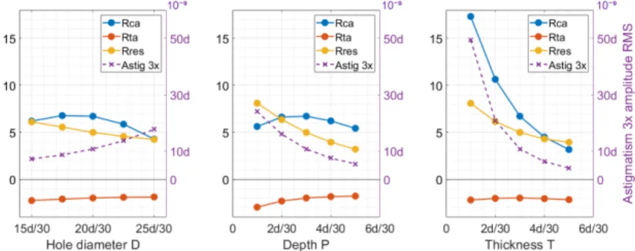
To iterate upon the initial trefoil thickness distribution, additional design parameters are investi-gated to minimise the unwanted aberrations and increase the magnitude of coma 3x in the warping function. Figure 5 is a 3D representation of the design with a trefoil thickness distribution, a cross section in the xz plan is performed to highlight the different parameters used in the study. Three parameters describe the ring: 𝑃 the depth of the central hole, 𝐷 the diameter of the hole and 𝑆 the amplitude of the thickness distribution. 𝑇 is central thickness of the mirror substrate. The amplitude of the thickness distribution 𝑆 is fixed at 3𝑑/30 as it generates the higher 𝑅𝐶 𝑜𝑚𝑎/ 𝐴𝑠𝑡𝑖𝑔in the first investigation, presented in Fig. 4 middle. Figure 6 highlights the change in ratios with diameter 𝐷 (left), depth 𝑃 (middle), and thickness 𝑇 (right). The magnitude of astigmatism 3x generated in the deformation is added as an indicator of the force required to reach the desired magnitude. A low magnitude of astigmatism 3x corresponds to a greater force required by the actuators, which is not desired due to the constraint of the elastic limit. Each of the plots demonstrate that the effect of 𝑅𝑇 𝑟 𝑒 𝑓 𝑜𝑖𝑙/ 𝐴𝑠𝑡𝑖𝑔is approximately invariant with increasing diameter, depth, or thickness.
Figure 6 left shows the variation of the hole 𝐷, from 𝐷 = 15𝑑/30 to 𝐷 = 25𝑑/30. A hole diameter of 17.5𝑑/30 generates the highest 𝑅𝐶 𝑜𝑚𝑎/ 𝐴𝑠𝑡𝑖𝑔; however, with 𝐷 = 20𝑑/30 the 𝑅𝑅𝑒𝑠𝑖 𝑑𝑢 𝑎𝑙 𝑠is reduced and the magnitude of astigmatism 3x increases for a similar 𝑅𝐶 𝑜𝑚𝑎/ 𝐴𝑠𝑡𝑖𝑔, as such the parameter 𝐷 was fixed to 20𝑑/30 for the remaining studies (Fig. 6 middle and Fig. 6
Fig. 5. 3D representation of the trefoil thickness distribution design, with a cross section in the xz plan in grey, highlighting the design parameters of the study: 𝑆,𝑇,𝑃 and 𝐷. 𝑡𝑒
is the minimum border thickness. The design configuration is taken with 𝑃 > 𝑆 in this example.
Fig. 6. Evolution of 𝑅𝐶 𝑜𝑚𝑎/ 𝐴𝑠𝑡𝑖𝑔, 𝑅𝑇 𝑟 𝑒 𝑓 𝑜𝑖𝑙/ 𝐴𝑠𝑡𝑖𝑔and 𝑅𝑅𝑒𝑠𝑖 𝑑𝑢 𝑎𝑙 𝑠as a function of
𝐷(left), 𝑃 (middle) and 𝑇 (right). The evolution of the astigmatism 3x is emphasised by the dashed line and with a dedicated axis on the right hand-side of the plots. right).
In Fig. 6 middle, the depth variation shows a maximum 𝑅𝐶 𝑜𝑚𝑎/ 𝐴𝑠𝑡𝑖𝑔when 𝑃 = 𝑆. When 𝑃 < 𝑆, the thickness distribution merges with the central thickness 𝑇, meaning that the minimum thickness at the border 𝑡𝑒is less than 𝑇. As a result, the warping function is then affected as we can see with the decrease of 𝑅𝐶 𝑜𝑚𝑎/ 𝐴𝑠𝑡𝑖𝑔when 𝑃 < 𝑆 . By increasing the depth (𝑃 > 𝑆), the residuals are dampened by the thickness of the hole and less present upon the optical surface; however, the amount of astigmatism 3x also decreases, which means that more force is needed to reach the desired magnitude.
Different trends are observed in the ratios as a function of mirror thickness 𝑇. Both 𝑅𝐶 𝑜𝑚𝑎/ 𝐴𝑠𝑡𝑖𝑔 and astigmatism 3x increase sharply for decreasing 𝑇, 𝑅𝑅𝑒𝑠𝑖 𝑑𝑢 𝑎𝑙 𝑠also increases but at a slower rate. However, having a high central thickness 𝑇 dampens the warping function, resulting in a loss of astigmatism 3x amplitude and a higher 𝑅𝑅𝑒𝑠𝑖 𝑑𝑢 𝑎𝑙 𝑠ratio than the desired 𝑅𝐶 𝑜𝑚𝑎/ 𝐴𝑠𝑡𝑖𝑔. From these observations, the optimal model should have a low 𝑇, to maximise 𝑅𝐶 𝑜𝑚𝑎/ 𝐴𝑠𝑡𝑖𝑔and the amplitude of astigmatism 3x, and a high 𝑃 to minimise the residuals.
3.3. Design constraint due to stress
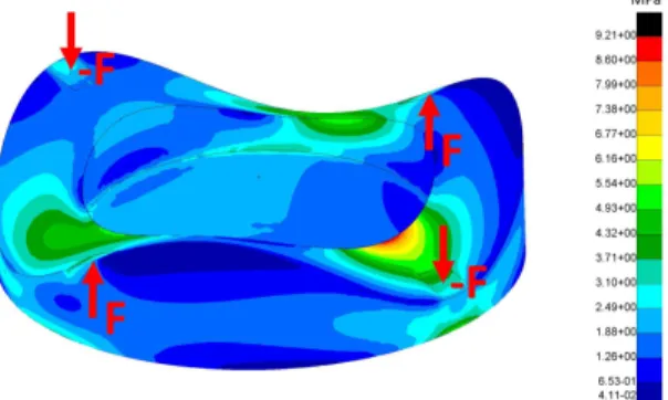
However, there are manufacturing considerations that negate the benefit of a low central thickness when considering the deformation required by SMP. For example, in Fig. 7, the von Mises stress fringes are mapped upon the mirror design with 𝑇 = 2𝑑/30, where 𝑑 = 30 mm and with a realistic force application of 20N. The maximum stress is located at the internal diameter of the ring where a force is applied on the minimal thickness border 𝑡𝑒. In this model the maximum von Mises stress is 9.21 MPa, which is below the safe design strength of Zerodur (10 MPa). In this case, decreasing the central thickness will increase the astigmatism amplitude, but exceed the safe design strength of Zerodur. Respecting the constraint on the allowable von Mises stress provides a boundary in the design of the mirror and therefore, the minimal central thickness recommended is 𝑇= 2𝑑/30.
Fig. 7. Von Mises stress computed on the model 𝑑=30 mm, 𝑆=3 mm, 𝑇=2 mm, 𝑃=3 mm with total load of 20 N on each force application surface, resulting in 627 nm RMS astigmatism displacement.
3.4. Final designs
From the described design investigations, the solutions to generate the OAP geometry via SMP are adapted to the RST CGI OAP requirements. CGI OAP diameters are larger than the example model, therefore the designs are scaled appropriately. In the configuration where 𝑑 = 60 mm, the optimal design becomes 𝑇 = 4 mm, 𝑃 = 6 mm, and 𝑆 = 6 mm, this model generates a 𝑅𝐶 𝑜𝑚𝑎/ 𝐴𝑠𝑡𝑖𝑔 = 4.51% on the clear aperture, corresponding to a deformation between the OAP6 and the OAP7 requirement (Table 2). Starting with OAP7 requirements as a baseline, the design was adjusted to ensure the correct 𝑅𝐶 𝑜𝑚𝑎/ 𝐴𝑠𝑡𝑖𝑔and amplitude of astigmatism 3x on the 22 mm clear aperture, which gave the final 𝑆, 𝑇, and 𝑃 values of 7 mm, 5 mm, and 7 mm respectively. The final design is presented in Fig. 8 left with the thickness distribution in light grey and the mirror substrate in dark grey; the displacement fringes on the optical surface after FEA deformation are presented in Fig. 8 right.
From the baseline design of OAP7 in Fig. 8 left, similar adjustments of the model were implemented to match the specifications of the entire set of OAPs. In many cases, the design stayed in configuration 𝑃 = 𝑆. However, in the case of larger clear aperture, 𝑃 was increased with respect to 𝑆, taking the advantage of 𝑃 reducing the residuals while maintaining a constant 𝑅𝐶 𝑜𝑚𝑎/ 𝐴𝑠𝑡𝑖𝑔. Table 3 summarises the performance reached for each OAPs with their optimised 𝑆, 𝑇 and 𝑃 parameters.
The majority of the OAPs are in the specification for the RST CGI; however, OAP1 and OAP2 show higher residuals due to their larger clear aperture and the border effect of the warping function. Further investigations are on-going, for example: using the shape optimisation method developed by S.Lemared et al. (2020) [37] that aims to improve the thickness distribution;
Fig. 8. OAP7 CAD representation (left). Displacement fringes upon the optical surface after FEA deformation in mm (right).
Design parameters OAP1 OAP2 OAP3 OAP4 OAP5 OAP6 OAP7 OAP8
S [mm] 4 3 4.5 6.5 6.5 6.5 7 3 T [mm] 3 2.5 6 3.1 4 4 5 2 P [mm] 7.5 7.5 6 7 6.5 6.5 7 3 Zernike coefficients Astig 3x RMS [nm] 1288 1447 381 201 170 170 102 174 Coma 3x RMS [nm] 102.2 108.8 19.1 12.0 8.1 8.1 3.9 7.0 𝑅𝐶 𝑜𝑚𝑎/ 𝐴𝑠𝑡𝑖𝑔[%] 7.92 7.52 5.02 5.94 4.72 4.72 3.82 3.99 𝑅𝐶 𝑜𝑚𝑎/ 𝐴𝑠𝑡𝑖𝑔Spec [%] 7.70 7.60 5.00 5.97 4.71 4.71 3.92 4.02 Residuals RMS [nm] 28.1 31.9 10.6 3.7 2.5 2.5 1.5 1.6
Table 3. Zernike aberrations obtained by FEA for each OAP of the RST CGI computed on the respective clear aperture with the calculated design parameters.
accommodating the RST CGI optical design to incorporate the surface errors; or, taking the advantage of finishing techniques, such as MRF and IBF to remove surface errors.
4. Experimental methodology and polishing
The parameters of OAP7 were selected for the first prototype because it was the most advanced design ready for manufacturing and it was considered low risk due to exhibiting the minimal value of astigmatism 3x for the CGI OAP set. The Zerodur substrate was made by SCHOTT from the design shown in Fig. 8 left, the thickness distribution was created by milling the shape into the Zerodur blank. A chamfer of ∼1 mm was added and polished on to the edge of the 60 mm physical diameter to prevent micro-cracks during polishing.
First, the substrate is polished spherically to obtain the required radius of polishing (Table 2) and to remove the machining defects upon the substrate surface. During this first step, significant material is removed; the central thickness of the OAP7 𝑇 is reduced to 4.43 mm and a new simulation is performed to verify the deformation function in Table 4: simulation. The material removal at the spherical polishing stage must be considered upstream in the design process. Figure 9 left highlights the OAP7 after spherical polishing, the resulting reflective surface is
suitable for direct interferometric measurement at 𝜆= 633 nm.
The warping harness is assembled on the back side of the mirror in Fig. 9 right. The interfacing components where force is applied have to be precisely mounted; 3D printed counter-form tools help to locate the gluing zones. The pushing forces are realised by pads glued upon the thickness distribution and topped by two micrometer screws. The pulling forces are achieved by wires glued both on the thickness distribution and the ring, the wires ensure a normal force. To apply the deformation the screws are turned, which deforms the ring and pulls upon the wires.
The substrate and its warping harness are placed front of an interferometer to start the deformation function. The prototype is mounted to allow access to the screws and to prevent constraints upon the mirror during the measurement. The warping harness is adjusted in front of the interferometer to produce the correct fringe pattern and then the substrate is left to settle under constraint for 12 hours to stabilise the warping function. The deformation obtained is shown in Table 4: deformation.
Fig. 9. OAP7 after unwarped spherical polishing phase, giving a reflective optical surface (left). OAP7 optical face down, assembled with its warping harness composed by a ring, two micrometer screws for the pushing forces and two wires for the pulling forces (right).
Zernike coefficients Specification Simulation Deformation Astig 3x RMS [nm] 102 102 99.6
Coma 3x RMS [nm] 4 4.5 4.42
𝑅𝐶 𝑜𝑚𝑎/ 𝐴𝑠𝑡𝑖𝑔 3.92% 4.39% 4.43%
Í𝑅 𝑒 𝑠𝑖 𝑑 𝑢 𝑎𝑙 𝑠RMS [nm] ≤5 1.8
-Table 4. A comparison of the Zernike aberrations for OAP7 with a clear aperture of 22 mm at design specification, simulation and experimentation. The residuals of the deformation are not recorded as they include contributions from an unstable measurement environment and interferometric errors.
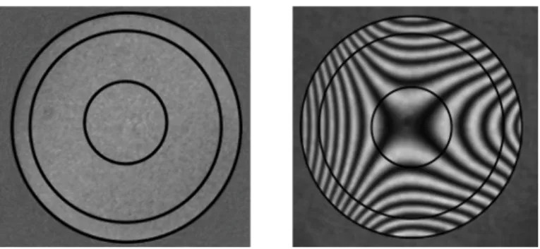
After the validation of the deformation, the substrate is polished under stress to imprint the warping function upon the reflective surface. The warping harness requires adjustments during polishing as vibrations slightly alter the stability of the warping function. Thus, several iterations of interferometric measurements and polishing phases allow convergence upon a flat interferogram, which confirms the perfect sphere and indicates the polishing completion, as shown in Fig. 10 left. In the final stage, forces are removed and final interferometric measurement is performed to validate the OAP surface shape as shown in Fig. 10 right.
Fig. 10. Flat interferogram at the end of the stress polishing (left) and the final Interferogram with the force released (right). Black circles correspond to the diameters 22 mm, 50 mm and 58 mm.
5. Results
A complete characterisation of the prototype surface is performed; the optical quality of the mirror is characterised in the three spatial frequency domains, as described in Section 2.1. The assessment of the LoF SFE and MidF SFE is validated with the phase map acquisition from interferometric measurement performed on the complete polished surface of 58 mm in diameter, the number of pixels on this diameter is 870. Figure 11 shows the phase maps at 50 mm and 22 mm diameter computed with the Intelliwave software from the interferometric fringe image (Fig. 10 right). The measurement on the 50 mm diameter is added to provide an insight on how the process is expected to scale for the larger clear aperture diameter OAPs. On the clear aperture of 22 mm, the number of pixels is 330 corresponding to a maximal spatial frequency of 165 c/p, which covers the LoF and MidF domains.
Fig. 11. Phase map of the final surface computed by Intelliwave software from fringe acquisitions taken with a M ¥𝑜ller-Wedel V-100 interferometer combined with a spherical reference surface of diameter 100 mm at F/6, resulting in a spatial resolution of 80 𝜇m. The surface maps are in nm for both the 50 mm diameter (left) and 22 mm diameter
(right).
The MidF SFE is evaluated with the PSD calculation from the surface phase map obtained by the interferometry in Fig. 11. Figure 12 left shows the phase maps computed after removing the first 36 Zernike polynomials (corresponding to the LoF SFE below 3 c/p) on five different zones to characterise the entire mirror surface; the central zone corresponds to the clear aperture of the mirror, and four additional zones on the border of the mirror are termed East, West, North and South. The PSDs obtained are then compared to the theoretical requirement, defined by the function 31/ 𝑓2.5, in Fig. 12 right. All the measured zones show a better quality than the theoretical function and particularly for the highest spatial frequencies.
Fig. 12. Phase map computed after removing the first 36 Zernike polynomials on the five zones: Centre, East, West, North and South (left); PSDs for each of the five zones, superimposed with the specification function defined as 31/ 𝑓2.5(right).
Roughness is evaluated using a microscope interferometer (WYKO NT9100). Five zones are measured on the surface: the centre, and at 11 mm and 25 mm from the centre along the x and y axes, as shown in Fig. 13 left. For each location a Mirau objective X50 is used with two magnifications giving 62 × 47 𝜇m2 and 126 × 94 𝜇m2of surface area measured with spatial resolution of 100 nm and 200 nm. 25 measurements are averaged and tip, tilt and piston are subtracted. Figure 13 right shows the roughness obtained for each zone at the two magnifications. Roughness is computed using the arithmetic average of the profile deviation Ra; on the 22 mm clear aperture and the 50 mm measurement aperture the average Ra in both instances is 2.1 ˚𝐴 to 1 decimal place.
Fig. 13. Sketch of the measurement roughness location upon the optical surface (left). Results of the roughness for each location and magnification after averaging the 25 measurements (right).
Further to the results on the 22 mm diameter, the measurements on the 50 mm diameter were also analysed to explore scaling to larger clear aperture diameter OAPs. On the 50 mm diameter the LoF SFE demonstrated 21 nm RMS, which includes a 19 nm RMS contribution from pentafoil and this represents the border effect simulated for the large clear aperture OAPs. As discussed in Section 3.4, it is anticipated that the border effect can be removed using additional manufacturing steps. The MidF SFE at 50 mm, calculated from the phase map in Fig. 11 left, already meets the CGI OAP requirements.
The results obtained on the surface quality in terms of LoF SFE, MidF SFE and roughness for both diameters, are summarised in Table 5. The results meet the requirements on the 22mm aperture for OAP7 and correspond to the FEA simulations. The very low roughness confirms the super-polishing on the mirror surface.
Requirement Specification Final Results Final Results Clear aperture [mm] 22.0 22.0 50.0 Polishing Roc [mm] 1416.6 +/-1 1417.4 +/-0.1 1417.4 +/-0.1 Astig 3x RMS [nm] 102.0 102.4 533 Coma 3x RMS [nm] 4.0 3.9 58 𝑅𝐶 𝑜𝑚𝑎/ 𝐴𝑠𝑡𝑖𝑔[%] 3.92 3.81 10.9 LoF SFE RMS [nm] 5 1.5 21 MidF SFE RMS [nm] 2 1.4 +/-0.3 1.7 Roughness [ ˚𝐴] 5 RMS 2.1 Ra 2.1 Ra
Table 5. Summarised final specifications as built of the OAP7 compared to the requirement, on the clear aperture at 22 mm and on a larger diameter at 50 mm.
6. Conclusion
In this paper we detail a new manufacturing process for OAP mirror fabrication, which broadens the range optical geometries manufacturable via the SMP technique. Investigating the design of the mirror substrate, we created an innovative thickness distribution composed of trefoil, which is capable of producing the OAP geometry while maintaining a simple warping harness system. The key design parameters to adapt the thickness distribution to a wide range of OAP geometries were highlighted and demonstrate the versatility of the approach. A prototype corresponding to the OAP7 model of the Roman Space Telescope CGI is manufactured in Zerodur and tested. The experimental results confirm the suitability of SMP for high contrast imaging: the optical quality of the OAP7 prototype is within the specifications, with a surface form error deviating from the simulation by < 1 nm RMS and an average surface roughness of 2.1 ˚𝐴 Ra. Further investigations to attenuate the border effect in the case of large clear aperture OAPs and to implement the technique on more complex shapes, such as freeforms, are under study.
Acknowledgements
The authors would like to acknowledge the European commission for funding this work through the Program H2020-ERC-STG-2015 - 678777 of the European Research Council. The authors also would like to acknowledge the JPL team for their support in this project.
Disclosures
The authors declare no conflicts of interest.
References
1. J. Angel, “Ground-based imaging of extrasolar planets using adaptive optics,” Nature 368, 203–207 (1994). 2. Beuzit, J.-L., Vigan, A., Mouillet, D., Dohlen, K., Gratton, R., Boccaletti, A., Sauvage, J.-F., Schmid, H. M., Langlois,
M., Petit, C., Baruffolo, A., Feldt, M., Milli, J., Wahhaj, Z., Abe, L., Anselmi, U., Antichi, J., Barette, R., Baudrand, J., Baudoz, P., Bazzon, A., Bernardi, P., Blanchard, P., Brast, R., Bruno, P., Buey, T., Carbillet, M., Carle, M., Cascone, E., Chapron, F., Charton, J., Chauvin, G., Claudi, R., Costille, A., De Caprio, V., de Boer, J., Delboulbé, A., Desidera, S., Dominik, C., Downing, M., Dupuis, O., Fabron, C., Fantinel, D., Farisato, G., Feautrier, P., Fedrigo, E., Fusco, T., Gigan, P., Ginski, C., Girard, J., Giro, E., Gisler, D., Gluck, L., Gry, C., Henning, T., Hubin, N., Hugot, E., Incorvaia, S., Jaquet, M., Kasper, M., Lagadec, E., Lagrange, A.-M., Le Coroller, H., Le Mignant, D., Le Ruyet, B., Lessio, G., Lizon, J.-L., Llored, M., Lundin, L., Madec, F., Magnard, Y., Marteaud, M., Martinez, P., Maurel, D., Ménard, F., Mesa, D., Möller-Nilsson, O., Moulin, T., Moutou, C., Origné, A., Parisot, J., Pavlov, A., Perret, D., Pragt, J.,
Puget, P., Rabou, P., Ramos, J., Reess, J.-M., Rigal, F., Rochat, S., Roelfsema, R., Rousset, G., Roux, A., Saisse, M., Salasnich, B., Santambrogio, E., Scuderi, S., Segransan, D., Sevin, A., Siebenmorgen, R., Soenke, C., Stadler, E., Suarez, M., Tiphène, D., Turatto, M., Udry, S., Vakili, F., Waters, L. B. F. M., Weber, L., Wildi, F., Zins, G., and Zurlo, A., “Sphere: the exoplanet imager for the very large telescope,” A@AND@A 631, A155 (2019).
3. B. Macintosh, J. R. Graham, P. Ingraham, Q. Konopacky, C. Marois, M. Perrin, L. Poyneer, B. Bauman, T. Barman, A. S. Burrows, A. Cardwell, J. Chilcote, R. J. De Rosa, D. Dillon, R. Doyon, J. Dunn, D. Erikson, M. P. Fitzgerald, D. Gavel, S. Goodsell, M. Hartung, P. Hibon, P. Kalas, J. Larkin, J. Maire, F. Marchis, M. S. Marley, J. McBride, M. Millar-Blanchaer, K. Morzinski, A. Norton, B. R. Oppenheimer, D. Palmer, J. Patience, L. Pueyo, F. Rantakyro, N. Sadakuni, L. Saddlemyer, D. Savransky, A. Serio, R. Soummer, A. Sivaramakrishnan, I. Song, S. Thomas, J. K. Wallace, S. Wiktorowicz, and S. Wolff, “First light of the gemini planet imager,” Proc. Natl. Acad. Sci. 111, 12661–12666 (2014).
4. D. Spergel, N. Gehrels, C. Baltay, D. Bennett, J. Breckinridge, M. Donahue, A. Dressler, B. S. Gaudi, T. Greene, O. Guyon, C. Hirata, J. Kalirai, N. J. Kasdin, B. Macintosh, W. Moos, S. Perlmutter, M. Postman, B. Rauscher, J. Rhodes, Y. Wang, D. Weinberg, D. Benford, M. Hudson, W. S. Jeong, Y. Mellier, W. Traub, T. Yamada, P. Capak, J. Colbert, D. Masters, M. Penny, D. Savransky, D. Stern, N. Zimmerman, R. Barry, L. Bartusek, K. Carpenter, E. Cheng, D. Content, F. Dekens, R. Demers, K. Grady, C. Jackson, G. Kuan, J. Kruk, M. Melton, B. Nemati, B. Parvin, I. Poberezhskiy, C. Peddie, J. Ruffa, J. K. Wallace, A. Whipple, E. Wollack, and F. Zhao, “Wide-field infrarred survey telescope-astrophysics focused telescope assets wfirst-afta 2015 report,” (2015).
5. T. Fusco, G. Rousset, J.-F. Sauvage, C. Petit, J.-L. Beuzit, K. Dohlen, D. Mouillet, J. Charton, M. Nicolle, M. Kasper, P. Baudoz, and P. Puget, “High-order adaptive optics requirements for direct detection of extrasolar planets: Application to the sphere instrument,” Opt. Express 14, 7515–7534 (2006).
6. R. Soummer, A. Ferrari, C. Aime, and L. Jolissaint, “Speckle noise and dynamic range in coronagraphic images,” The Astrophys. J. 669, 642–656 (2007).
7. M. C. Noecker, F. Zhao, R. Demers, J. Trauger, O. Guyon, and N. J. Kasdin, “Coronagraph instrument for WFIRST-AFTA,” J. Astron. Telesc. Instruments, Syst. 2, 1 – 6 (2016).
8. V. P. Bailey, M. Bottom, E. Cady, F. Cantalloube, J. de Boer, T. Groff, J. Krist, M. A. Millar-Blanchaer, A. Vigan, J. Chilcote, E. Choquet, R. J. D. Rosa, J. H. Girard, O. Guyon, B. Kern, A.-M. Lagrange, B. Macintosh, J. R. Males, C. Marois, T. Meshkat, J. Milli, M. N’Diaye, H. Ngo, E. L. Nielsen, J. Rhodes, G. Ruane, R. G. van Holstein, J. J. Wang, and W. Xuan, “Lessons for WFIRST CGI from ground-based high-contrast systems,” in Space Telescopes and Instrumentation 2018: Optical, Infrared, and Millimeter Wave,vol. 10698 M. Lystrup, H. A. MacEwen, G. G. Fazio, N. Batalha, N. Siegler, and E. C. Tong, eds., International Society for Optics and Photonics (SPIE, 2018), pp. 1913 – 1925.
9. L. Pogorelyuk and N. J. Kasdin, “Dark hole maintenance and a posteriori intensity estimation in the presence of speckle drift in a high-contrast space coronagraph,” The Astrophys. J. 873, 95 (2019).
10. K. Dohlen, A. Vigan, D. Mouillet, F. Wildi, J.-F. Sauvage, T. Fusco, J.-L. Beuzit, P. Puget, D. L. Mignant, R. Roelfsema, J. Pragt, H. M. Schmid, R. Gratton, D. Mesa, R. Claudi, M. Langlois, A. Costille, E. Hugot, J. O’Neil, J. C. Guerra, M. N’Diaye, J. Girard, D. Mawet, and G. Zins, “SPHERE on-sky performance compared with budget predictions,” in Ground-based and Airborne Instrumentation for Astronomy VI, vol. 9908 C. J. Evans, L. Simard, and H. Takami, eds., International Society for Optics and Photonics (SPIE, 2016), pp. 1089 – 1099.
11. T. Magner, J. Zaniewski, S. Rice, and C. Fleetwood, “Fabrication and testing of off-axis parabolic mirrors,” Opt. & Laser Technol. 19, 91 – 96 (1987).
12. D. Wang, Y. Sui, H. Yang, and D. Li, “Adaptive spiral tool path generation for diamond turning of large aperture freeform optics,” Materials 12 (2019).
13. H. L. Gerth, R. E. Sladky, M. J. Bezik, and C. A. Washington, “Fabrication of Off-Axis Parabolic Mirrors,” Opt. Eng. 17, 588 – 594 (1978).
14. R. A. Jones, “Computer-Controlled Optical Surfacing With Orbital Tool Motion,” Opt. Eng. 25, 785 – 790 (1986). 15. R. A. Jones, “Fabrication of a large, thin, off-axis aspheric mirror,” Opt. Eng. 33, 4067 – 4075 (1994).
16. D. W. Kim, C.-j. Oh, A. Lowman, G. A. Smith, M. Aftab, and J. H. Burge, “Manufacturing of super-polished large aspheric/freeform optics,” in Advances in Optical and Mechanical Technologies for Telescopes and Instrumentation II,vol. 9912 (International Society for Optics and Photonics, 2016), p. 99120F.
17. D. W. Kim and J. H. Burge, “Rigid conformal polishing tool using non-linear visco-elastic effect,” Opt. express 18, 2242–2257 (2010).
18. D. Golini, W. I. Kordonski, P. Dumas, and S. J. Hogan, “Magnetorheological finishing (MRF) in commercial precision optics manufacturing,” in Optical Manufacturing and Testing III, vol. 3782 H. P. Stahl, ed., International Society for Optics and Photonics (SPIE, 1999), pp. 80 – 91.
19. C. Supranowitz, C. Hall, P. Dumas, and B. Hallock, “Improving surface figure and microroughness of IR materials and diamond turned surfaces with magnetorheological finishing (MRF),” in Window and Dome Technologies and Materials X,vol. 6545 R. W. Tustison, ed., International Society for Optics and Photonics (SPIE, 2007), pp. 208 – 218.
20. L. N. Allen, J. J. Hannon, and R. W. W. Jr., “Final surface error correction of an off-axis aspheric petal by ion figuring,” in Active and Adaptive Optical Components, vol. 1543 M. A. Ealey, ed., International Society for Optics and Photonics (SPIE, 1992), pp. 190 – 200.
Eng. 34, 3565 – 3571 (1995).
22. B. Schmidt, “A coma-free telescope,” Mitt. Hamburg Sternv 7, 15 (1932).
23. E. Everhart, “Making corrector plates by schmidt’s vacuum method,” Appl. Opt. 5, 713–715 (1966). 24. G. Lemaître, “New procedure for making schmidt corrector plates,” Appl. Opt. 11, 1630–1636 (1972). 25. G. R. Lemaitre, “Active optics with a minimum number of actuators,” Adv. Opt. Technol. 3, 223 – 249 (2014). 26. Hugot, E., Ferrari, M., El Hadi, K., Costille, A., Dohlen, K., Rabou, P., Puget, P., and Beuzit, J. L., “Active
optics methods for exoplanet direct imaging - stress polishing of supersmooth aspherics for vlt-sphere planet finder,” A@AND@A 538, A139 (2012).
27. M. N’Diaye, E. Choquet, S. Egron, L. Pueyo, L. Leboulleux, O. Levecq, M. D. Perrin, E. Elliot, J. K. Wallace, E. Hugot, M. Marcos, M. Ferrari, C. A. Long, R. Anderson, A. DiFelice, and R. Soummer, “High-contrast Imager for Complex Aperture Telescopes (HICAT): II. Design overview and first light results,” in Space Telescopes and Instrumentation 2014: Optical, Infrared, and Millimeter Wave,vol. 9143 J. M. O. Jr., M. Clampin, G. G. Fazio, and H. A. MacEwen, eds., International Society for Optics and Photonics (SPIE, 2014), pp. 644 – 654.
28. J. Lubliner and J. E. Nelson, “Stressed mirror polishing. 1: A technique for producing nonaxisymmetric mirrors,” Appl. Opt. 19, 2332–2340 (1980).
29. J. E. Nelson, G. Gabor, L. K. Hunt, J. Lubliner, and T. S. Mast, “Stressed mirror polishing. 2: Fabrication of an off-axis section of a paraboloid,” Appl. Opt. 19, 2341–2352 (1980).
30. H. Tang, R. Demers, J. Krist, J. McGuire, M. Rud, and F. Zhao, “The WFIRST coronagraph instrument optical design update,” in Techniques and Instrumentation for Detection of Exoplanets VIII, vol. 10400 S. Shaklan, ed., International Society for Optics and Photonics (SPIE, 2017), pp. 1 – 8.
31. R. J. Noll, “Zernike polynomials and atmospheric turbulence∗,” J. Opt. Soc. Am. 66, 207–211 (1976).
32. D. Ramos-López, M. Sánchez-Granero, M. Fernández-Martínez, and A. Martínez–Finkelshtein, “Optimal sampling patterns for zernike polynomials,” Appl. Math. Comput. 274, 247 – 257 (2016).
33. R. Navarro and J. Arines, “Complete modal representation with discrete zernike polynomials - critical sampling in non redundant grids,” in Numerical Simulations of Physical and Engineering Processes, J. Awrejcewicz, ed. (IntechOpen, Rijeka, 2011), chap. 10.
34. P. Hartmann, “Zerodur®: deterministic approach for strength design,” Opt. Eng. 51, 124002 (2012). 35. SCHOTT, “Zerodur®: Zero expansion glass ceramic - catalogue,” Tech. rep., SCHOTT (2011). 36. P. Fricker, “Zernike polynomials,” MATLAB Central File Exchange (2020). Retrieved March 3, 2020.
37. S. Lemared, M. Ferrari, C. D. Jeu, T. Dufour, N. Soulier, and E. Hugot, “Stress mirror polishing for future large lightweight mirrors: design using shape optimization,” Opt. Express 28, 14055–14071 (2020).