HAL Id: hal-01100737
https://hal.inria.fr/hal-01100737
Submitted on 6 Jan 2015
HAL is a multi-disciplinary open access
archive for the deposit and dissemination of
sci-entific research documents, whether they are
pub-lished or not. The documents may come from
teaching and research institutions in France or
abroad, or from public or private research centers.
L’archive ouverte pluridisciplinaire HAL, est
destinée au dépôt et à la diffusion de documents
scientifiques de niveau recherche, publiés ou non,
émanant des établissements d’enseignement et de
recherche français ou étrangers, des laboratoires
publics ou privés.
Bridging the Gap: Automated Steady Scaffoldings for
3D Printing
Jérémie Dumas, Jean Hergel, Sylvain Lefebvre
To cite this version:
Jérémie Dumas, Jean Hergel, Sylvain Lefebvre. Bridging the Gap: Automated Steady Scaffoldings
for 3D Printing. ACM Transactions on Graphics, Association for Computing Machinery, 2014, ACM
Transactions on Graphics (TOG) - Proceedings of ACM SIGGRAPH 2014, 33 (4), pp.98:1 - 98:10.
�10.1145/2601097.2601153�. �hal-01100737�
Bridging the Gap: Automated Steady Scaffoldings for 3D Printing
Jérémie DumasUniversité de Lorraine, INRIA
Jean Hergel
INRIA, Université de Lorraine
Sylvain Lefebvre INRIA, Université de Lorraine
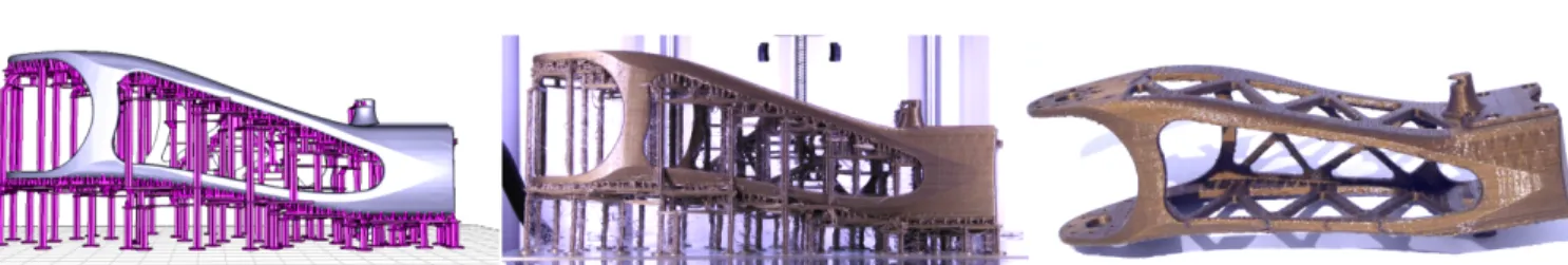
Figure 1: The upper leg of the Poppy robot (www.poppy-project.org) cannot be 3D printed on low cost FDM printers without support. Our technique automatically generates scaffoldings made of horizontal bridges supported by vertical pillars, shown in purple. The print is shown in the middle and on the right after clean up. Bridges are strong and stable, increasing the print reliability while having a low material usage.
Abstract
Fused Filament Fabrication (FFF) is the process of 3D printing ob-jects from melted plastic filament. The hot plastic exits a nozzle and fuses with the part just below, adding a layer of material to the ob-ject being formed. However, filament can only be deposited on top of an existing surface. Therefore, overhangs require a disposable support structureto be printed, temporarily supporting the threads of plastic that would otherwise hang in empty space.
Existing techniques for support generation fall into two categories: The first allow for very reliable prints by enclosing the bottom of the object in a dense structure, at the expense of increased material usage and build times. The second generate thin hierarchical struc-tures connecting to the surface in a sparse number of points. This uses less material, at the expense of reliability: the part might be-come unstable, the structure itself may bebe-come difficult to print, the bottom surface quality degrades. The user therefore has to correct the structure and its parameters for each new object.
We propose to exploit the ability of FFF printers to print bridges across gaps. Since bridges are always supported by pillars at their extremities, they are both stronger and more stable than hierarchical tree structures. Our technique first selects the points to support based on overhang and part stability during the entire print process. It then optimizes for a printable scaffolding composed of bridges and vertical pillars, supporting all points. The result is an automated support generation technique using little material while ensuring fine surface quality and stability during the printing process. CR Categories: I.3.5 [Computer Graphics]: Computational Geom-etry and Object Modeling; I.3.8 [Computer Graphics]: Applications Keywords: FDM, FFF, 3D Printing, Scaffoldings, Supports
Links: DL PDF
1
Introduction
Fused filament fabrication (FFF) is a popular technique for turning 3D models into real, tangible objects. A hot filament is melted through a heated nozzle and fuses with the part just below, adding a layer of material to the object being formed. Advantages are the low cost of both printers and filaments, the relative ease of use requiring few manual steps before and after printing, and the wide availability of printers which can be bought from a variety of manufacturers, e.g. Ultimaker, RepRapPro, 3D Systems, Stratasys.
A major drawback of the process, however, is that filament can only be deposited on top of an existing surface. Therefore, overhangs require a disposable structure to be printed, temporarily supporting the threads of plastic that would otherwise hang in empty space. Most of the existing approaches build very reliable support struc-tures that unfortunately incur a large increase in used material and print time. Other approaches produce small support structures but rely on the user to fix an initial, incomplete automated solution. This trial-and-error process often requires multiple test prints. We discuss previous work Section 2.
We design our supports to answer two main criteria: 1) supporting plastic threads wherever necessary, while being easy to remove and 2) minimizing used material, while printing reliably. Material usage and reliability are contradictory goals: as the size of the support is decreased it becomes more delicate to print and mechanically fragile. In particular the weight of the object and the friction of the printing nozzle start to endanger the integrity of the structure. Support generation techniques focus on the issue of overhangs. This is, however, not the only situation in which support is required. Many objects are printed in a fragile equilibrium, or will have sub-parts in fragile equilibrium at a stage of the printing process. When support is required this issue propagates throughout the entire sup-port structure: a thin supsup-port has to be strong enough to supsup-port the weight imbalance of the subparts being printed above it. Our supports ensure that not only all overhangs are properly supported, but also that at all stages of the print process the already printed subparts of the object are maintained in a stable position.
Our structures are inspired from the scaffoldings used in construction. In particular, we exploit bridges — horizontal bars printed between mostly vertical pillars. Such bridges can be printed reli-ably by FFF printers over gaps of several centime-ters. These bridges exhibit good mechanical prop-erties and can support other layers of scaffolding.
— this particular scaffolding is made of the same geometry as the scaffoldings we use to support our prints. Despite bridges that are only two threads wide (0.8mm) and two layers thick (0.4mm), it withstands the 83 grams of a coffee cup — the rough equivalent of 35 meters of 1.75mm ABS plastic filament — most objects use less than 10 meters of filament and are supported by several bridges. The scaffolding weights 0.5g. These good mechanical properties led us to a scheme where we only consider the topology of the struc-ture: in all practical cases we encountered and despite printing at the smallest thicknesses ensuring reliability, our bridge structures proved sturdy enough.
Contributions. Our first contribution, described Section 4, is a novel way to select points to be supported based not only on over-hangs but also on the stability of the printed model throughout the entire build process. Our second contribution, described Section 5, is an efficient algorithm to build bridge scaffoldings that support a given sets of points in space. The structure itself preserves the balance of the print, while using little material. A major difficulty in computing the structure stems from the constraints ensuring that the result is printable: A bridge may only be printed if it is supported by a pillar in each of its extremities.
2
Related Work
Determining support requirements. Support generation algo-rithms start by a determination of the surfaces in need for support. A first family of approaches consider the down-facing facets of the input mesh having an angle too steep to print correctly (e.g. [Allen and Dutta 1995; Alexander et al. 1998]). A second family of ap-proaches consist in performing a boolean difference between two successive slices (e.g. [Allison et al. 1988; Chalasani et al. 1995; Huang et al. 2009a]). This generally leads to a compact set of points to be supported. Eggers and Renap [2007] select a subset by down-sampling. We follow a similar approach to Chalasani et al. [1995], considering whether the plastic deposition paths are correctly sup-ported by the layers beneath.
Support geometry. Once the surfaces requiring support are de-termined, the support geometry is computed. The main approach consists in extruding the mesh facets requiring support downward, thus defining a support volume. The support volume is usually printed with a weak infill pattern (KISSlicer, Makerware, [Strano et al. 2013]). The support is manually removed by breaking it apart from the object. Soluble material can also be used on multiple ma-terial printers [Kritchman et al. 2008]. Printing the support volume uses a significant amount of material and print time, but is very reli-able: the support typically has a large area of contact with both the part and the print bed, ensuring the print stability in most cases. The volume is large enough to print without difficulty.
A number of approaches modify the support volume to reduce its size. Huang et al. [2009b] use sloped walls instead of straight walls for the sides, shrinking the support volumes in their middle sections. Heide [2011] also reduces the support volume by decreasing its size and complexity as the distance below the supported model increases. Several approaches have been proposed to find a model orientation reducing the size of the support volume [Frank and Fadel 1995; Allen and Dutta 1995; Cheng et al. 1995; Alexander et al. 1998; Majhi et al. 1999]. We do not consider this issue in our work, and assume that the part orientation has been fixed by the user consider-ing other criteria (steppconsider-ing error, mechanical robustness, aesthetics of filament orientation).
MeshMixerby Autodesk deviates from the support volume and in-stead builds a thin structure supporting the part in a sparse, limited
number of points. MeshMixer automatically generates an initial support resembling a tree. The precise algorithm is, to our knowl-edge, undisclosed. This work elegantly shows that a very sparse structure can effectively serve as a support. MeshMixer however of-ten requires the user to fix up the initial structure (see comments on Thingiverse, thing 131054), and the slanted trees sometimes suffer from print reliability issues (see Figure 17). In contrast, our bridges offer similar grouping properties as a tree but print more reliably. Wang et al. [2013] optimize truss structures for the primary purpose of strengthening 3D printed objects, and extend their approach for support generation. Support beams are added by tracing rays down-wards, within a tolerance cone ensuring that the result is printable. The beams are not grouped, missing an opportunity to reduce print time and material usage.
Eggers and Renap [2007] propose to form a support structure by starting from a regular rhombus mesh filling the print bed. The 3D model is subtracted from the initial structure, removing intersected mesh edges. Points requiring support are attached to the mesh by downward angled beams. A number of heuristics are proposed to reduce the number of beams in the support structure. This approach, however, has to ensure that large enough columns are formed so that the support mesh remains printable. In contrast we optimize for thin elongated bridges that are guaranteed to remain printable. Our approach does not suffer from the orientation bias resulting from canceling edges in a pre-existing mesh.
Adobe Photoshop CC, released on January 16th 2014, includes sup-port generation for 3D printing. Available screenshots reveal that square-section pillars are grown from the ground with a hierarchical tree structure to connect to the surface.
Topology and truss optimization. Truss optimization tech-niques select and deform the edges of an over-complete initial truss mesh [Smith et al. 2002; Wang et al. 2013]. While we initially con-sidered a similar formulation, it is difficult to ensure that the result remains printable: the topological optimization is free to remove pillars that are in fact necessary to print the horizontal bridges. This issue also applies to other techniques for topology optimization [Al-laire 2006] which — preformance concerns apart — cannot easily guarantee that the result can be fabricated.
Stability during printing. Parts may topple during printing, ei-ther due to weight imbalance [Chalasani et al. 1995] or under the friction forces of the printing head. To the best of our knowledge, no approach considers the automatic construction of a support structure ensuring that the printed parts remain stable at all stages of the print-ing process. Indeed, an object may be balanced once printed, but its — possibly disconnected — subparts may not be stable before all layers are completed. Our approach adds a small set of support points ensuring stability during printing.
A number of other techniques consider geometry and mechanical properties of objects in the context of 3D printing. Stava et al. [2012] add struts to reinforce objects but do not consider support generation nor overhang constraints. Prevost et al. [2013] deform and carve objects to obtained balanced objects after fabrication.
3
Our Method
We discuss in Section 3.1 our choice of using vertical pillars for the main structure, and compare it with trees. Section 3.2 discusses the printing of bridges on FDM printers. Section 4 describes the se-lection of the points required for supporting the printed model. Our selection ensures both that deposited filament is properly supported, but also that the printed parts remain stable at all times, throughout
the printing process. Section 5 introduces our bridge construction algorithm: the generation of the geometry of the support structure once the required support points have been determined. We con-clude with results and comparisons in Section 6.
3.1 Analysis
An appealing option when designing support structures is to rely on hierarchical tree-like structures. This is a choice worth considering since the support pillars quickly regroup before reaching the printing bed. Therefore, one can expect less material to be used and a smaller print time.
However, this incurs several difficulties. First, printing slanted pil-lars is generally less reliable than printing vertical pilpil-lars. The slope induces a smaller bonding area between layers and an uneven warp-ing durwarp-ing cool down. The reliability varies upon the room tem-perature, the plastic filament quality, and the layer height settings. Printing vertical pillars is much less sensitive to these factors. Sec-ond, even when the structure prints properly, the supported weight and the forces applied by the print head on the upper levels generate torque on the base pillar(s). This bends the structure, and resulting deformations can lead to print failures. In contrast our scaffoldings are stable by construction: the pillars on each side of the bridges prevent the bending of the structure.
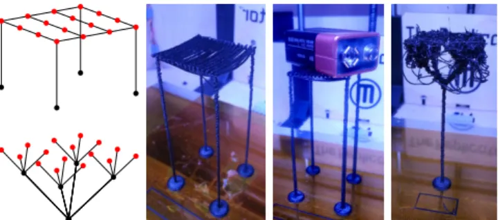
One might expect the tree structure to use less material than a bridge structure, thanks to the hierarchical grouping. But as we now dis-cuss, and perhaps somewhat counter-intuitively, bridge structures are in fact comparable to tree-structures. Let us consider a grid of 2k× 2k
points spaced evenly by one unit (millimeters) on a same horizontal plane. An example is shown Figure 2 for k = 2. The grid side length is2k− 1 mm. We consider the case of a tree-structure with pillars at45 degrees. Grouping all points down to a single pillar requires a total pillar length of Lt(k) = 2k(2k+1− 2). The tree then has a height of 2k√−1
2 . A bridge structure for the same points at the same height requires a total pillar length of Lb(k) = 2(2k − 1)(1 +
√
2 + 2k−1). It can be seen that for k >= 3 the bridge is more efficient than the tree. However, as the height further increases the tree grows a single pillar while the bridge grows four. We consider the height at which a tree-structure and a bridge-structure use the same pillar length as a function of k; that is h such that Lt(k) + h = Lb(k) + 4h. For instance, for supporting16×16 points (k = 4) spaced by 1 mm the tree becomes interesting again after56 mm. By this time we reach the configura-tion shown Figure 2 where the tree fails to print properly. In contrast, the four pillars stabilize the bridge structure, making it more reliable to print at higher heights and able to support significant weights.
3.2 Bridge Printing Reliability
Our bridges are two layers thick and two threads wide, with a small spacing (0.4 mm) in between both threads. To print bridges at rel-atively high speeds (60 mm/sec) we force the extrusion of a small amount of plastic prior to printing horizontal bridge segments (0.1 mm of filament). Our bridges are designed to print quickly, which negatively impacts their appearance — in particular, the first printed threads often sag. This has however little impact on the quality of the top of the bridge, as detailed in Figure 3. While all results shown in the paper are printed on a Makerbot Replicator 1 with ABS plas-tic, we also tested our bridges successfully on an Ultimaker 2 with PLA plastic, using same parameters. Our scaffolding algorithm is independent from the exact geometry used to print bridges. The bridges are mechanically robust despite their small size (see Section 1). Two 30 mm bridges can for instance support the entire Minotaur model of Figure 17 with little deflection (< 0.3 mm).
Figure 2: Left, top: A bridge structure supporting a grid of4 × 4 points.Left, bottom: Corresponding tree structure. Pictures, from left to right: A bridge structure 78mm tall, the same structure supporting a 9 volt battery, the equivalent tree (same amount of filament). The tree cannot support such weight without toppling. In addition, the top of the tree failed to properly print due to extruder friction.Printed at 60mm/sec on a Replicator 1 Dual with ABS plastic.
Figure 3: We printed bridges of 30 mm length in batches, along the X, Y axis and at a 45 degree angle. All the bridges printed successfully with a flat top surface. However, the first threads of plastic often sag, resulting in an uneven underside. We measure the deflection to be 0.8 mm on average. In 12% of the cases a first thread failed to connect and was dangling from the bridge.Printed at 60mm/sec on a Replicator 1 Dual with ABS plastic extruded at 220◦C.
4
Support Points
The first step of our approach is to determine a set of points that require support. There are two aspects to this process: supporting filament and ensuring part stability. We start by determining where filament needs support: these points are required regardless of sta-bility, whereas the stability analysis of the overall part depends upon the already placed support points.
4.1 Supporting Filament
Our approach starts by slicing the model without any support, deter-mining the full set of print paths. Each print path is a sequence of segments along which plastic has to be deposited. The print paths are of two types: the perimeters which follow the outer boundary of the surface and the infills which fill the interior of the volume. Our algorithm walks along each print path and checks whether each segment endpoint is properly supported by the layer just below. The test considers the coverage of a disk having for diameter the size of the print nozzle (0.4mm in our setup). If more than 50% of the disk lies outside the object on the layer below, we consider the endpoint unsupported — this threshold was determined experimentally to ensure good surface quality. In practice, we implement the test using images of the layers with 0.05mm pixel resolution. We only check segment end points since the segments themselves form bridges if their extremities are supported. However, in order to ensure a good quality for bottom surfaces, we restrict the longest segment length.
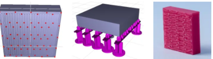
Figure 4: Cube hanging in space. Left: Set of points requiring sup-port.Middle: Generated scaffold. Right: Bottom surface quality.
Algorithm 1: Select support points
Input: Array of paths P, stored as array of points, ordered by Z %. Output: Set of points S to be supported.
1 foreach perimeter perim ∈ P do 2 foreach u ∈ perim do 3 if isUnsupported(u) then
4 if @v ∈ S s.t. v ∈ perim and C(u, v) < τ then
5 S ← S ∪ {u}
6 foreach non perimeter path ∈ P do 7 foreach u ∈ path do
8 if isUnsupported(u) then
9 if @v ∈ S s.t. z(v) 6 z(u) and ||u − v|| < τ then
10 S ← S ∪ {u}
11 return S
This is done by re-sampling any segment whose length exceeds a threshold (5mm in our implementation).
This simple analysis does not take into account the fact that when a point is supported, a whole length of filament around it can be considered supported as well — the cooling filament having a non negligible rigidity. This is the case on perimeters. This effect turns into a surface support when filaments are deposited side by side, for instance when filling an area with a tight infill pattern (see [Cha-lasani et al. 1995] for a nomenclature of such cases). We therefore select only a subset of the detected points. Pseudo code is given by Algorithm 1. C(u, v) denotes the curvilinear distance between two points u and v on a same print path; τ is the canceling distance (2mm in our implementation); isUnsupported tests the disk cov-erage test using the layer directly below the point. Figure 4 shows the result for a box hanging in empty space.
4.2 Ensuring Part Stability
Once the points required for supporting filament are determined, we consider the stability of the printed part. When printed layer by layer an object made of a single component often starts as discon-nected subparts which regroup at higher heights (see Figure 5). At an intermediate stage, each of the disconnected sub-parts may be subject to instabilities and topple, leading to a print failure. Our analysis algorithm therefore proceeds in a bottom-up manner, ana-lyzing layer after layer the stability of each subpart independently until they regroup.
We assume next that there is no gluing force between the bed and the printed object — a conservative assumption since any existing gluing force only improves stability. We also assume that the part is rigid when checking for equilibrium and stability.
Stability conditions. Verifying whether a rigid body lying on a surface is under static equilibrium involves two main concepts: the
Figure 5: Left: A stable object. Right: At an earlier stage of print-ing the object is made of four disconnected components. The center of mass (red dot) of the full object (left) projects onto the ground (green dot) within the base of support (orange polygon). At an ear-lier stage of printing (right) the object is made of four disconnected components which are unstable and may topple if unsupported. As can be seen the projected CoM lies outside of the BoS.
center of mass(CoM) of the object as well as its base of support (BoS). For an object of volumeΩ of homogeneous density ρ the center of mass is defined as Com(Ω) = ρ
R
Ωxdx. In the case of FDM printed object, the volumeΩ to consider is not the volume defined by the mesh, but instead the volume resulting from the ac-cumulation of plastic filament — this is especially important when sparse infill patterns are used within the object interior. The BoS is the convex hull of the points of the printed part in contact with the print bed. Our goal is to increase the BoS to ensure stability, through the addition of support points and bridges.
A rigid body lies in static equilibrium on a plane orthogonal to grav-ity if its CoM projects into the BoS (e.g. [Prévost et al. 2013]). This equilibrium might however be unstable if small perturbations — for instance due to the print head — make the object topple. We take these perturbations into account by verifying whether a disk of ra-dius r around the projected CoM lies entirely within the base of support. This is an approximation, and we choose for radius a con-servative estimate of 3mm in our implementation. A more elaborate scheme would change the radius depending of the distribution of mass around the CoM and the distance to the BoS; we did not find this necessary.
When a subpart is detected as unstable we add support points to increase its base of support. This is only possible because the base of support of our scaffoldings always contains all the projected support points: the bridges are always supported by vertical pillars at their extremities.
Algorithm. Our algorithm sweeps through layers from bottom to top. At each layer, we render an image of the print paths (one pixel per0.05 mm) and use it to keep track of the 3D connected components. Note that this only requires the images of the current layer and the layer directly below. An example of layer image is shown in Figure 6, right.
We compute the CoM of each component by summing the coordi-nates of the pixels belonging to it — each pixel represents a small volume of matter having a same unit mass. Using the image of the print paths properly accounts for infill patterns within the object. While sweeping through layers we keep track of the current BoS of each 3D component (Figure 6, right, green polygons). A BoS is a convex hull and therefore its geometric complexity remains small. Each BoS is initialized at the first layer, where the filament is in direct contact with the print bed: we add all the pixel coordinates belonging to a component to its BoS. At each layer, we include in the BoS the support points detected for the filament. We then check whether the disk of radius r centered on the projected CoM is entirely within the BoS (Figure 6, right, orange circles). If that is the case for all components we continue to the next layer.
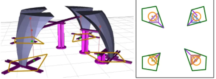
Figure 6: Left: Bridge structure stabilizing the part: the projected CoMs are now within the BoSs. Right: Image of a layer created during stability analysis. The print paths are color-coded with the ID of their 3D connected component. The orange circle are the CoM disks, the green polygons the current BoS of each component. The purple segments are the added stabilizing bridges at this stage. They maintain the orange CoM circle within the green BoS polygon. If the CoM disk leaves its BoS new support points have to be added. During the sweep we keep track of candidate points for each com-ponent: these are points on the bottom surface of the object that are not projecting in the component BoS. By supporting these points we have an opportunity to enlarge the BoS of the component. We do not consider the candidate point directly but a circle of points around it. The radius is the same as for the CoM disk. This guarantees that we can always enlarge a BoS to cover the CoM disk.
To enlarge a BoS we iteratively add points until the CoM disk is fully covered. At each iteration we add the candidate enlarging the BoS with the largest coverage of the CoM disk. Due to the arbitrary insertion order, some points added in the first iterations may no longer contribute to the final BoS. We remove these and tag the selected points as requiring support. The added points may not be in contact with the surface, in which case we add a small bridge between the candidate point and the surface point (Figure 6, right, purple segments). This bridge is given as an input to the scaffolding algorithm.
Figure 6, left illustrates the bridge structure resulting from the stabil-ity analysis only. Note in particular how the BoS has been enlarged by adding bridges at the first layer, providing an automated raft feature for small contact surfaces with the bed. Timings for this algorithm are summarized in Table 1.
5
Scaffolding
We now describe how the geometry of our support structure is gen-erated, given the set of points to be supported. We seek to generate a structure so that:
- the structure is formed by vertical pillars and horizontal bridges, - all required points are properly supported by vertical pillars, - the vertical pillars connect either to the print bed, to horizontal
bridges located below, or to the object itself.
- all horizontal bridges are supported at their extremities, by ver-tical pillars, by other bridges, or by connecting to the object. This last point guarantees that the structure is printable on an FDM printer. We search for a structure using a small amount of plastic while enforcing these constraints.
Our initial attempts at formulating an integer problem in a regular grid, capturing the constraints between horizontal bridges and ver-tical pillars resulted in impracver-tical computation times — it did not terminate but for the simplest examples. This formulation is de-scribed in the supplemental material. We therefore propose a greedy optimization algorithm.
We design our algorithm with the ability to create bridges in several directions in the XY plane. This is important since a strong
direc-tional bias — such as axis aligned bridges only — would generate a larger number of pillars when supporting features at an angle. We also note that while thin slanted pillars become less reliable as their length increases, they can print reliably on short distances. This is particularly useful when trying to support several points with a rectilinear bridge: perfect alignments are unlikely. Our algorithm therefore has the ability to connect vertical pillars to other elements by adding a small slanted connector at their top.
5.1 Bridge Gain and Score
Our algorithm enumerates and selects new bridges that improve the current solution. It therefore requires a function to estimate the benefit of a new bridge. We approximate the bridge benefit by counting the gain and loss in terms of pillar and bridge length.
Z hb
wb
lmin
lmax Following notations in the inset, a bridge of
length wbat height hbsupporting k elements provides a gain of Gain(b) = (k − 2)hb− wb. Clearly, only bridges supporting more than two points can be beneficial. Our algorithm only inserts bridges where Gain(b) > 0.
When deciding which bridge to insert we com-pute a score for each bridge. The score is: Score(b) = Gain(b) − k · lmax(b), where lmax(b) is computed as the maximum length
of the structure connecting an element above to the bridge. It takes into account non vertical parts that may occur when an element above is not in the vertical plane of the bridge. The score penalizes uneven distributions of connection lengths above the bridge. The bridge giving the best (possibly negative) score will be selected. In cases where the bridge extremities are above the object, we use the free length of each vertical pillar instead of the bridge height: Gain(b) = k · hb− h1− h2− wbwith h1and h2the heights of the pillars before reaching the object.
lmin(see the inset) is a parameter fixing the minimal distance be-tween a bridge and a supported point (1.6 mm in our implemen-tation). Note that lowering the bridge would only reduce its gain. Thus bridges have maximal gain at a distance lminbelow the lower of the elements they support. This provides a way to efficiently enumerate possible bridge heights.
5.2 Construction Algorithm
The input to our bridging algorithm is a set of points and bridges that have to be supported. The bridges come from the stability analysis (Section 4.2). We also input a representation of the 3D model allowing for fast line intersection tests — this can be any of the common ray-tracing data-structures.
The output of the algorithm is a set of horizontal bridges and vertical pillars forming a correct (printable) bridge structure while having a small size. Each computed bridge and pillar is turned into actually geometry before 3D printing (Section 5.3).
Sweep strategy. Our algorithm iteratively searches for possible bridges throughout the volume, adding those with the highest score. Since the set of points requiring support is sparse only a small num-ber of possible bridges has to be considered.
Our approach is based on a sweep strategy. Possible bridges are enumerated by sweeping a vertical plane along a fixed direction in the XY-plane. For the sake of clarity let us assume in the following that the selected sweep direction is the X axis. We thus sweep a YZ plane along the X axis, stopping at a number of events. The events represent opportunities to create bridges orthogonal to the sweep
X Y
sweep
bridges?
Figure 7: Two bridges and an isolated point as well as their cor-responding anchoring segments for a sweep along the X axis. The green squares are events considered during the sweep. The pur-ple line illustrates the YZ sweep plane when examining one event. Bridges will be searched along the Y and Z axis. All intersected anchoring segments are an opportunity for a new bridge to support existing bridges and points.
direction that support other bridges and points located above. The events are the end points and intersections of a number of anchoring segmentsdescribing where bridges and points can be supported.
Anchoring segments for bridges. A bridge is represented by a solid segment supporting elements above. Two anchoring segments — one on each extremity — represent where the bridge can be sup-ported from below: the interval of possible endpoints for this bridge. The anchoring segments for a bridge are outlined in green in Fig-ure 7. Their length is chosen to enforce a longest bridge constraint (30 mm in our implementation).
Supporting pillars from below can connect anywhere along the an-choring segments. Once connected, the bridge extends to the pillar and the anchoring segment is removed. The remaining anchoring segment, if any, is updated to enforce the longest bridge constraint. We name this operation a snap, and name open bridge a bridge with two open anchoring segments and a half-open bridge a bridge with a single open anchoring segment. The exact size of the bridge is only determined once both of its anchoring segments are snapped.
X Z
Anchoring segments for points. Points are sup-ported by pillars grown either from the ground or from a bridge located below. Using only vertical pillars would require a perfect alignment between bridges and points, an unlikely event. Instead, our algorithm allows small slanted bars to be used at the top of vertical pillars, as illustrated in the inset. To ensure printability we
con-strain the ratio between the offset at the top and the height of the slanted bar. The two dashed lines in the inset show extremal con-figurations, with the point either exactly above the pillar or at the largest admissible offset (5 mm in our implementation).
Anchoring segments for a point depend on the sweep direction. They are illustrated in orange in Figure 7. The anchoring segments for points are created each time a new sweep direction is selected. Note that we consider the extremities of the solid segment of a bridge as points to be supported (Figure 7). If one extremity is snapped, the corresponding bridge anchoring segment is removed.
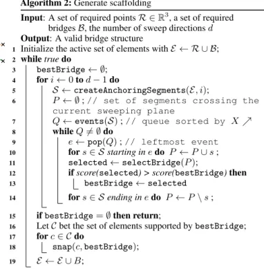
Complete algorithm. The full pseudo-code is given in Algo-rithm 2. At every iteration (line 2) the algoAlgo-rithm starts with a num-ber of (half-)open bridges and points and attempts to snap as many as possible by adding a new bridge supporting them from below through pillars. When the algorithm cannot find beneficial bridges (G(b) > 0) it stops (line 15).
The algorithm considers multiple sweep directions at each iteration (line 4). Let us assume that the problem is rotated each time to align
Algorithm 2: Generate scaffolding
Input: A set of required points R ∈ R3, a set of required bridges B, the number of sweep directions d Output: A valid bridge structure
1 Initialize the active set of elements with E ← R ∪ B; 2 while true do
3 bestBridge ← ∅;
4 for i ←0 to d − 1 do
5 S ← createAnchoringSegments(E, i);
6 P ← ∅ ; // set of segments crossing the
current sweeping plane
7 Q ← events(S) ; // queue sorted by X % 8 while Q 6= ∅ do
9 e ← pop(Q) ; // leftmost event 10 for s ∈ S starting in e do P ← P ∪ s ;
11 selected ← selectBridge(P );
12 if score(selected) > score(bestBridge) then
13 bestBridge ← selected
14 for s ∈ S ending in e do P ← P \ s ; 15 if bestBridge= ∅ then return;
16 Let C bet the set of elements supported by bestBridge;
17 for c ∈ C do
18 snap(c, bestBridge); 19 E ← E ∪ B;
the sweep direction with the X axis. Possible bridges are enumer-ated by sweeping the YZ plane along the X axis, stopping at each event(lines 7-8). The events are the end points and intersections of all anchoring segments — the intersection being computed after projection on the XY plane, i.e. ignoring the Z coordinate. Figure 7 illustrates the set of events for a simple case.
createAnchoringSegmentscreates all anchoring segments for bridges and points (see Figure 7); events computes all events for the sweep (green squares in Figure 7). At each event, we con-sider the bridges that can be formed along the Y axis, connecting the segments currently intersected by the sweep plane. Bridges can exist at different heights: we consider the heights just below each of the anchoring segments (see Section 5.1). This is performed by selectBridge(line 11), described in Algorithm 3.
In Algorithm 3, each bridge snapping more than two points is eval-uated by the functions addSupported and evalBridge which implement the bridge gain and score evaluation described in Sec-tion 5.1. The gain and score are computed assuming that the current endpoints are supported by straight pillars — which is an approxima-tion of the final soluapproxima-tion. The score takes into account the increase in length of the bridges located above that are snapped to the new bridge (see lmaxin Section 5.1). Candidate bridges are tested for collisions by collisions: this checks whether a collision occurs between the model, the bridge and each connector to the elements above it. This takes into account collisions with already placed bridges. The collision tests can be accelerated thanks to the fixed number of directions and the limited set of points to consider. Finally, snap (line 18, Algorithm 2) snaps the extremity c of an element located above to the newly added bridge B by creating a vertical pillar topped (if necessary) by a small slanted pillar. For instance, that would be the case where the purple line in Figure 7 intersects orange segments: a slanted bar is necessary to cover the horizontal gap from the point to the bridge. Note that the distance between the point and the intersection along the anchoring segments constrains the height of the bridge. This is taken into account by z(c) in Algorithm 3, together with the minimum distance between a bridge and an element, lmin.
Algorithm 3: Select a bridge along a given plane
Input: Set of segments P intersecting the sweep plane YZ at current event
1 C ← {P ∩ Y Z} ; // intersections sorted by Y % 2 Z ← {z(c), c ∈ C} ; // sorted by Z %
3 for z ∈ Z do
4 for i1← 0 to size(C) − 1 do
5 A ← ∅ ; // points supported by bridge 6 for i2← i1to size(C) − 1 do
7 if kC[i2] − C[i1]k 6 maxDist then
8 addSupported(A, C[i2]);
9 if collisions(A, i1, i2, z) then break ;
10 (gain, score) ← evalBridge(A, i1, i2, z);
11 if gain > 0 and score > bestscore then
12 bestbridge ← currentBridge
13 return bestbridge
Model Dim. Max # Elm. # Iter Bridging CoM Knot 45.9mm 155 4 263ms 3.9s Servojoint 65.6mm 195 21 676ms 7.3s Gymnast 98.8mm 114 17 712ms 19.3s Bunny 5cm 55.0mm 302 42 18s 283ms 2.6s Hilbert 30.0mm 262 26 3s 776ms 1.2s Minotaur 99.5mm 391 49 43.2s 13.9s Enterprise 152.8mm 823 75 1min 12s 24.2s DNA 94.8mm 867 104 4min 17s 16.7s
Table 1: Executions times on a variety of models. Note that in some cases the new bridge might be able to support two anchoring segments of a same bridge located above ; i.e. a bridge anchoring segment and a point anchoring segment. This case can be seen for the rightmost segment and the purple sweep line in Figure 7. If there is more than one possibility to snap an element to the current bridge, only the one yielding the connector of smallest length is considered.
Complexity Algorithm 2 has a total time complexity of O(d · (n + k)n3· c · b), where d is the number of sweeping direc-tions, n the number of points to support, k the number of inter-sections between the segments projected on the XY plane, c the maximum time complexity of a collision test, and b the number of newly added bridges during the main loop of Algorithm 2. Note that this is only an upper bound, and that in practice the execution time of the whole process is reasonable (see Table 1). Several fac-tors are favorable. First, the iterations for different sweep directions are trivial to parallelize. Second, the number of segments input to selectBridgecan be much smaller than the total number of ele-ment n (not all anchoring segele-ments intersect). Finally, for each new bridge that is added all the points it supports are removed, making subsequent iterations within Algorithm 2 faster.
We measured the execution time of our parallel implementation on an Intel R
CoreTM i7-4770K @ 3.50GHz with 8 threads, 32 GB RAM and a GeForce GTX Titan. We used d= 8 sweeping direc-tions (angular increments of π8 due to symmetry). As we can see in Table 1, the timing for most real-world examples are under five minutes and we believe there is room for further optimizations.
Connecting to the object. The ex-tremities of a bridge may connect to the top of the surface below by a vertical pil-lar. As an alternative, we also consider snapping bridges to the object sides, as
illustrated in the inset. For each bridge considered in line 10 of Algo-rithm 3, we also consider extended the same bridge with endpoints until touching the surface (up to the maximum allowable length). Such a candidate bridge simply has one of its h{1,2}equals to0 in the calculation of its score and gain (Section 5.1). We retain the candidate bridge with the best score.
5.3 Producing the Final Geometry
The final geometry is an union of box and cylinder primitives. We rely on cross-section pillars that we found more reliable to print than cylinders. Bridges are formed of two parallel one-thread thick seg-ments, across two layers. Figure 8 reveals the main components of our bridge structures. Our slicer processes union of meshes without suffering from inter-penetration issues.
We adapt our slicer [?] for printing the scaffoldings. In each slice we erode by 0.2mm the bridge structure where it comes in contact with the object. This helps the removal of parts of the structure connecting to the object. For sideway connections to the object (Figure 8, second closeup form the left) we add a one-layer thick protrusion from the object, providing a docking space for the bridge. This tiny loop of plastic easily breaks away.
Figure 8: From left to right: The gymnast model and its scaf-folding. A pillar, a sideway connector, vertical connectors sup-porting filament, the mid-air support for the right foot. Model: http://www.123dapp.com/123C-3D-Model/Female-Gymnastics-Cartwheel/711240
6
Results and Discussion
We compare the behavior of different methods running in automatic mode: we perform no manual editing of the proposed support struc-tures. Our technique runs with the exact same settings for all models. All models are printed on a Makerbot Replicator 1 Dual using ABS plastic at 40 mm/sec print speed for perimeters, 60 mm print speed for other print paths (including support) and 120 mm/sec travel speed, using layers of 0.2 mm height. The only exception is Table 2 where we match the settings of Makerware.
Figure 11 compares MeshMixer and our technique on the Enterprise 3D model. We generate a support in MeshMixer and load it into our slicer to compute the used filament length. We adjusted two parameters in MeshMixer: the angle threshold (40) and density (80) to match as closely as possible our support density. MeshMixer uses 9.7m of filament while our technique uses 9.89m — similar amounts. However, our approach ensures a more uniform support. This is visible under the propulsion units, but also under the main body. On this model, the support from Makeware (not shown) uses 18.8m of filament as it fills the space below the model. We show a comparison to Photoshop CC in Figure 12. With our technique long bridges supported by few pillars replace dense trees. Using param-eters from PhotoshopCC (Replicator 1 profile), PhotoshopCC uses 4.61m of filament in the support (11.97m total) versus 2.31m for our technique (9.48m total). Our printed version is shown Figure 9.
Figure 9: Top: Printout of the Enterprise model. Bottom: Under-side after cleanup. We broke the engine connectors during cleanup and had to glue them back (only case where glue was involved). Print time: 3h14, 9.89m of filament.
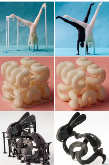
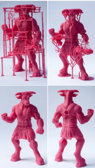
Figure 10: Comparison between MeshMixer (left) and our tech-nique (right). MeshMixer uses 6.7m of filament versus 7.66m for our technique. The tree generated by MeshMixer is fragile: a single pillar supports the entire weight of the arms through long slanted bars.Model: http://www.thingiverse.com/thing:46646 by user ajolivette
Figure 10 compares our technique and Mesh-Mixer on the Minotaur model. The model has heavy overhanging features (arms). MeshMixer uses 6.7m of filament but produces a precarious structure — this is a case where the user would have to manually reinforce the structure through the MeshMixer support editing interface. Our technique uses more plastic (7.66m) but has a denser support, is stable and prints reliably. Our
final print and the print from the MeshMixer mesh are shown Fig-ure 17. Makerware, shown in the inset, uses 10.8m of plastic. Table 2 summarizes other comparisons. In this table we use Maker-ware as the slicer for the MeshMixer output. We use 40 mm/sec for printing and 80 mm/sec for travel. We match the settings of Mak-erware in our slicer. MakMak-erware and MeshMixer explicitly avoid supporting the bridge overhangs in Servojoint. Our technique gives a rougher surface but the bond between layers is improved. De-spite the increase in required support points our structure remains three times smaller than the one of Makerware. Knot is a defavor-able case for our technique. Makerware and MeshMixer support
Figure 11: Comparison between MeshMixer (top) and our tech-nique (bottom). The middle row shows underside views. MeshMixer uses 9.7m of filament while we use 9.89m. Notice the much denser support we provide in particular to the rear of the ship.
Figure 12: Comparison between Photoshop CC (left) and our tech-nique (right).Model: thingiverse.com/thing:18346 by user JackSpectre.
Figure 13: Servojoint. Makerware, MeshMixer, Ours.
Figure 14: Knot. Makerware, MeshMixer, Ours.
Model: thingiverse.com/thing:5506 by chylld
Servojoint Knot Enterprise Minotaur
(Figure 13) (Figure 14) (Figure 9) (Figure 17)
Makerware Time 1h15 1h12 3h33 2h28 Filament 4.64m 4.17m 19m 10.1m MeshMixer ? Time 1h05 1h08 3h38 2h04 Filament 3.44m 3.85m 9.7m 6.7m Ours Time 1h14 1h20 3h14 2h37 Filament 3.86m 4.01m 9.89m 7.66m
Table 2: Comparison of time and total filament length. Print qual-ity varies, please refer to Figure 13 and Figure 14. (?) Generated with MeshMixer and sliced with Makerware.
Figure 15: Left: Scaffolding for the DNA model. Middle: After printing.Right: After cleanup. Print time: 3h36, 8.7m of filament. very few points through thin beams while our approach builds a full bridge. For this object, with both the Makerware and MeshMixer models we had to use a raft for the part to remain stable on the heated bed. In all other cases we use significantly less plastic than Makerware. Our print times are comparable to Makerware, which is in large part due to the printing of the many small connectors. We believe print times could be significantly reduced by grouping connectors supported by a same bridge into continuous connectors.
6.1 Additional Results
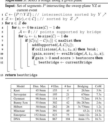
Figure 15 is a tall and intricate design mimicking the helix of DNA. Figure 16 shows three additional models with very differ-ent geometries. Note the elegant scaffolding generated for the Gymnast model. The Hilbert cube is a case where bridges have little room to exist — the scaffolding is nevertheless successfully created. Our version of the 5cm bunny peel model uses 1.97g of plastic versus only 0.75g for the MeshMixer version, which has been manually optimized (see http://www.thingiverse. com/thing:131054/#comments, user meshmixer). Figure 1 is printed with PLA plastic on an Ultimaker 2 with 0.3 mm layer height, all other parameters being the same.
6.2 Support Removal
Support detaches from the object when applying gentle force and we clean most objects by hand, sometimes using a small wire cutter on interleaved bridges in complex geometries. The support leaves faint white marks on the plastic — a default shared by all techniques. These can removed by heating the plastic or by finishing the part in acetone vapor. We did not apply such techniques to the results shown here. Soluble material could be used to print our structures.
6.3 Limitations
Our method does not consider the robustness of the printed object. It can be frustrating to discover that a perfect print with support is in fact too fragile — a difficulty worsened by the support removal step. The Enterprise model in Figure 9 is such a case: the thin connectors between the engines and the body (<1.5mm) broke during clean-up where they connect to the engines. We had to glue them back (no other model required gluing). Automatic methods exist for the purpose of reinforcing objects [Stava et al. 2012].
Our sweeping algorithm is unaware of the geometry of the object aside from the collision detection. For instance, it might miss an opportunity to create a bridge where there is a hole through the object. Analyzing the shape to guide the algorithm is an interesting avenue of future work. This is simple to integrate in our algorithm which already takes open bridges as input.
As explained Section 3.2 when printing a bridge the first thread fails
Figure 16: Models printed with our technique, scaffoldings on the left and cleanup model on the right. Top: The Gymnast model. Middle: The curved Hilbert cube model. Bottom: The 5cm Bunny Peel model.Hilbert cube model: thingiverse.com/thing:16343 by tbuser. Bunny peel model: thingiverse.com/thing:131054 by user meshmixer.
in approximatively 12 % of cases, leaving hanging filament in the print. This is visible in figures showing the print before cleanup. This has little impact on surface quality as falling filament cools quickly and does not bond with the surface below.
7
Conclusion
We have shown how to exploit a specific property of FFF printers — their ability to print bridges across gaps — to construct reliable scaffoldings. Their geometry gives to our scaffolding interesting me-chanical properties that makes them sturdier and more stable, even at the smallest thickness ensuring that they print correctly. Our struc-tures could probably benefit other processes such as stereolithogra-phy — but the set of requirements are different.
Further reducing the quantity of material usage while preserving reliability will require a precise modeling of the mechanical prop-erties of the structure and object throughout the print process. This is a challenging task since the plastic deposited in layers has an anisotropic behavior which we expect to become highly nonlinear on thin slanted structures. This is nevertheless an exciting venue of future work. In the meantime our technique provides a simple and reliable way to print interesting and complex geometries with a reasonnable material usage.
Figure 17: Top left: The Minotaur printed with our technique. Print time: 2h37m, 7.66m of filament.Top right: Attempt at printing the MeshMixer version. Print time (same parameters): 2h04, 6.7m of plastic. We also had to add a raft below each feet. On our model, the stability analysis automatically added a raft beneath each feet (visible in picture).Bottom: Model printed with our technique after clean up, front and back.
Acknowledgements
This work was funded by ERC grant ShapeForge (StG-2012-307877). We thank the anonymous reviewers for their help with improving the paper, our families for accepting the 3D printers at home for long print sessions, as well as the 3D printing community members who shared the models shown here.
References
ALEXANDER, P., ALLEN, S.,ANDDUTTA, D. 1998. Part ori-entation and build cost determination in layered manufacturing. Computer-Aided Design 30, 5, 343 – 356.
ALLAIRE, G. 2006. Conception optimale de structures. Springer. ISBN 3-540-36710-1.
ALLEN, S.,ANDDUTTA, D. 1995. Determination and evaluation of support structures in layered manufacturing.
ALLISON, J. W., CHEN, T. P., COHEN, A. L., SMALLEY, D. R., SNEAD, D. E., ANDVORGITCH, T. J., 1988. Boolean layer comparison slice. US Patent 5854748, 3D Systems Inc. CHALASANI, K., JONES, L.,ANDROSCOE, L. 1995. Support
generation for fused deposition modeling. In Solid Freeform Fabrication Symposium, 229–241.
CHENG, W., FUH, J., NEE, A., WONG, Y., LOH, H., AND
MIYAZAWA, T. 1995. Multi-objective optimization of part- build-ing orientation in stereolithography. Rapid Prototypbuild-ing Journal 1, 12–23.
EGGERS, G.,ANDRENAP, K., 2007. Method and apparatus for automatic support generation for an object made by means of a rapid prototype production method. US Patent 20100228369, Materialize.
FRANK, D.,ANDFADEL, G. 1995. Expert system-based selection of the preferred direction of build for rapid prototyping processes. Journal of Intelligent Manufacturing 6, 5, 339–345.
HEIDE, E., 2011. Method for generating and building support struc-tures with deposition-based digital manufacturing systems, 07. US Patent 20110178621 A1.
HUANG, X., YE, C., MO, J.,ANDLIU, H. 2009. Slice data based support generation algorithm for fused deposition modeling. Ts-inghua Science and Technology 14, S1, 223–228.
HUANG, X., YE, C., WU, S., GUO, K.,ANDMO, J. 2009. Sloping wall structure support generation for fused deposition modeling. The International Journal of Advanced Manufacturing Technol-ogy 42, 11-12, 1074–1081.
KRITCHMAN, E., GOTHAIT, H.,ANDMILLER, G., 2008. System and method for printing and supporting three dimensional objects, 04. US Patent 7364686.
MAJHI, J., JANARDAN, R., SMID, M.,ANDGUPTA, P. 1999. On some geometric optimization problems in layered manufacturing. Computational Geometry 12, 34, 219 – 239.
PRÉVOST, R., WHITING, E., LEFEBVRE, S., AND SORKINE -HORNUNG, O. 2013. Make It Stand: Balancing shapes for 3D fabrication. ACM Transactions on Graphics 32, 4, to appear. SMITH, J., HODGINS, J. K., OPPENHEIM, I.,ANDWITKIN, A. 2002. Creating models of truss structures with optimization. ACM Transactions on Graphics 21, 1.
STAVA, O., VANEK, J., BENES, B., CARR, N. A.,ANDMECH, R. 2012. Stress relief: improving structural strength of 3d printable objects. ACM Transactions on Graphics 31, 4, 48.
STRANO, G., HAO, L., EVERSON, R.,ANDEVANS, K. 2013. A new approach to the design and optimisation of support struc-tures in additive manufacturing. The International Journal of Advanced Manufacturing Technology 66, 9-12, 1247–1254. WANG, W., WANG, T. Y., YANG, Z., LIU, L., TONG, X., TONG,
W., DENG, J., CHEN, F., ANDLIU, X. 2013. Cost-effective printing of 3d objects with skin-frame structures. ACM Transac-tions on Graphics 32, 5.