HAL Id: inria-00099073
https://hal.inria.fr/inria-00099073
Submitted on 26 Sep 2006
HAL is a multi-disciplinary open access
archive for the deposit and dissemination of
sci-entific research documents, whether they are
pub-lished or not. The documents may come from
teaching and research institutions in France or
abroad, or from public or private research centers.
L’archive ouverte pluridisciplinaire HAL, est
destinée au dépôt et à la diffusion de documents
scientifiques de niveau recherche, publiés ou non,
émanant des établissements d’enseignement et de
recherche français ou étrangers, des laboratoires
publics ou privés.
Structuring the First Steps of Requirements Elicitation
Jeanine Souquières, Maritta Heisel
To cite this version:
Jeanine Souquières, Maritta Heisel. Structuring the First Steps of Requirements Elicitation. [Intern
report] A00-R-123 || souquieres00e, 2000, 4 p. �inria-00099073�
Structuring the First Steps of Requirements Elicitation
Jeanine Souqui`eres
Maritta Heisel
LORIA—Universit´e Nancy2 Fakult¨at f¨ur Informatik B.P. 239 Bˆatiment LORIA Universit¨at Magdeburg F-54506 Vandœuvre-les-Nancy, France D-39016 Magdeburg, Germany
[email protected] [email protected]
We propose to use a system classification and its asso-ciated diagrams to structure the first steps of requirements elicitation. With system diagrams, we introduce a set of components related by communication links, representing the system to be developed including its environment.
1
Introduction
The first steps in the requirements engineering process are often made difficult by the facts that :
Computer scientists do not know the application do-main of the system to be built very well.
Customers and domain experts do not have a clear vision of what the system should (and could) do for them.
Hence, a brainstorming process is necessary to bring the two parties together and achieve a common understanding of what the system should do.
Our method for requirements elicitation [HS98, HS99] explicitly contains informal steps that can be carried out in a brainstorming process. These steps are:
1. Fix the domain vocabulary.
2. State the facts, assumptions, and requirements con-cerning the system in natural language.
3. List the possible system operations. 4. List all relevant events, and classify them.
Although these steps seem to be quite concrete and well suited to structure a brainstorming process, it has turned out that they take quite some time in practice. In this paper, we present an approach to further structure the very first steps of requirements elicitation in order to speed up the brainstorming process.
The basic idea is to define classes of systems, where each system class is represented by a diagram. These diagrams–which follow the notational conventions of con-text diagrams [Jac95]–show the system to be built and its
environment, see for example Figure 1. Each box repre-sents a domain, and links between boxes mean that there is a direct communcation between them.
Even though clients may have difficulties to state re-quirements or to identify system operations or events, they usually are capable to decide if the purpose of the system to be developed is to control a physical process or rather to translate data. That is, given a system classification, it is easier to find the class the new system belongs to than to state concrete requirements for it.
Given the class a system belongs to, we can ask more concrete questions. We can try to identify a mapping be-tween the schematic domains of the system diagram and the application domains of the new system. We can ask how the communication between the system and the differ-ent domains takes place, thus iddiffer-entifying system operations and events. In this way, we obtain a goal-directed way of performing the first steps of requirements elicitation.
In the next section, we relate our work to other existing approaches, especially to Michael Jackson’s work. After-wards, we present our system classification.
2
Related Work
This work is mainly based on ideas of Michael Jack-son [Jac95]. JackJack-son introduces problem frames to charac-terize software development problems. These frames are represented by a frame diagram showing the machine to be built and the relevant application domains, together with the relations that have to hold between the different parts. In order to fit into a given problem frame, a concrete prob-lem must have certain properties.
Jackson’s approach is a classification approach. First, the problem to be solved must be described using a context or frame diagram, and stating the requirements as relations between application domains. Then, a problem frame must be found into which the problem fits. To decide if a prob-lem fits into a probprob-lem frame, Jackson proposes several tests. Once the right problem frame is found, the prob-lem can be solved using a method tailored for the probprob-lem
frame. Hence, the goal is to construct a solution of a given problem, based on given requirements.
In contrast, our approach is a constructive approach. Its goal is to derive the requirements that form the start-ing point of any solution process. We use a nomenclature and notation similar to Jackson’s, but with a different ob-jective. Deciding on a system class first helps to set up a context diagram. This in turn helps to ask the right ques-tions: each domain of the diagram and each connection between domains has to be discussed and characterized.
In this way, the very first steps of the requirements elic-itation process can be carried out in a structured and goal-directed way, i.e., the chosen problem class guides the way in which the different steps of our method (see Section 1) can be performed.
The system classes we have identified (see Section 3) contain more detail than Jackson’s problem frames. The system class descriptions must be detailed enough to pro-vide substantial guidance in the requirements elicitation process after the right system class has been chosen. On the other hand, too much detail makes it difficult to chose the right system class. We think that our system class de-scriptions are well balanced in this respect.
3
System Diagrams for Requirements
Elici-tation
To structure the first steps of requirements elicitation, we have identified several system classes, which we de-scribe in the following. For each system class, we give a
system diagram. System diagrams are similar to Jackson’s
context and frame diagrams in the following aspects: The part of the system to be constructed is shown as a box with a double outline.
Other relevant parts of the system are shown as simple boxes.
A link between two boxes means that there is a direct communication between them.
A blot on a communication link indicates that the part at the far end of the blot is contained in the part at the near end of the blot.
System diagrams differ from context and frame diagrams in that:
Some system parts may be optional. These (and the corresponding communication links) are shown with dashed lines.
We distinguish two kinds of communication links. Simple lines denote communications via events, whereas double lines denote communicationn via op-erations.
We do not show any requirements (rendered as ovals in frame diagrams) in our diagrams.
We now briefly discuss five different system classes.
3.1
Control System
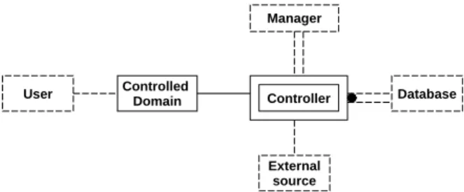
The purpose of a control system is to control some phys-ical process. Such a system is characterized by the fact that users do not directly communicate with the controller, but via intermediate physical devices. Figure 1 shows the cor-responding system diagram.
User Controller Manager External source Database Controlled Domain
Figure 1: Control System Diagram
If the optional parts of the diagram do not exist, the sys-tem is purely reactive. Otherwise, it also has transforma-tional parts. User ATM Bank Database ATM hardware insert_card enter_PIN enter_amount eject_card keep_card recharge debit_account
Figure 2: System diagram for the tellermachine
An example of a control system is an automatic teller machine (ATM), shown in Figure 2 [HS99]. Users com-municate with the ATM via physical devices such as a card reader and a keyboard. The communication is per-formed by events, for example insert card, enter PIN, or
enter amount. The bank that runs the ATM must recharge
the machine from time to time. In the database, informa-tion about cards is stored.
3.2
Data Managment System
The goal of a data management system as shown in Fig-ure 3 is to update and maintain a database. It is a pFig-urely transformational system. Different kinds of users may be involved in such a system, each of them with different rights and operations.
In a library (see Figure 4), readers have access to the library data management system, for example to find infor-mation about books or about their borrowed books. The library staff has additional rights, for example to add or to remove books from the information system. The managed
User Manager Managed Domain Database Intermediate User
Figure 3: Data Managment System Diagram
domain corresponds to the books on the shelves, and the database component models these books.
Reader Library Books Database Staff Put Get Add-book Add-reader Request
Figure 4: System Diagram for the Managment of a Library
3.3
Visualization System
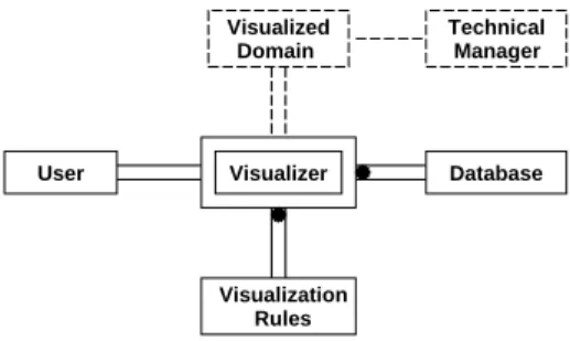
The main goal of a visualization system as shown in Figure 5 is to extract and visualize information from a database. A visualization rule base contains the rules for visualizing information associated with the problem do-main.
User Visualizer Database Visualized Domain Technical Manager Visualization Rules
Figure 5: Visualization System Diagram
An example of a visualization system where the data base part is an important one is a travel planning system that allows its users to plan trips from one town to another, using different means of travelling as shown in Figure 6. Information about means of travelling are extracted from the database, and the results of the database queries are visualized on the screen.
User Travel
Planning Database
Visualization Rules
Figure 6: System Diagram for travel planner
3.4
Transformer System
Another important system class are transformer systems that translate data, see Figure 7. An example of such a system is a compiler.
User Transformer Database Target
Source
Figure 7: Transformer System Diagram
3.5
Diagnostic System
The last class of systems we want to sketch are diag-nostic systems. Here, the user interacts directly with the system by means of operations. Measuring devices com-municate with the system via events.
Diagnose Domain Diagnose User Domain Rules Database Measuring Devices
Figure 8: Diagnostic System Diagram
A patient monitoring system is an example of a diagnos-tic system. The database stores information about patients. The diagnose domain are the patients and their diseases. The database rules specify whether the measurements de-livered by the devices are in a safe range or not. If not, a nurse (which takes the role of the user) has to be notified.
3.6
How to Use System Diagrams in
Require-ments Elicitation
The choice of a system diagram structures the early brainstorming phases of the requirements elicitation pro-cess. It helps to establish a firm basis for the communica-tion between customers and suppliers and to proceed in a goal-directed way.
Once a system class is chosen, each component of the corresponding system diagram must be instantiated. In do-ing so, the relevant vocabulary of the problem domain is introduced, and it is verified that the characteristics of the different components are indeed satisfied.
A very important point is the identification of the differ-ent kinds of users. Having achieved this iddiffer-entification, it is easier to identify the system operations that are to be pro-vided for each user group. Another point concerns the in-teraction of each user with their related domain, what Jack-son calls shared phenomena. With which components will each user interact?
Other important questions to ask when instantiating a system diagram are the following:
Do we have to take a database into account?
Can we identify distinguished components as interme-diates between the system and the users (connection do-mains [Jac95])? For each of them, we have to fix the vo-cabulary.
The distinction between reactive and transformational system can also help : a system is purely reactive if it has only a direct communication with its users. This means that only operations and no events have to be identified.
4
Conclusion
The work presented in this paper is based on the ob-servation that one can distinguish different purposes of software-based systems on a high level of abstraction, for example “manage data” or “control a process”. The differ-ent purposes correspond to differdiffer-ent system classes.
For each system class, we can identify its principal parts [Jac95] that must be present, e.g., an application domain for which data must be managed, or a domain that must be controlled. We can also identify character-istic communication patterns between the principle parts. For example, data bases are queried and manipulated via operations, whereas a control system has to react to events. Hence, we can set up paradigmatic system dia-grams (which are similar to Jackson’s frame diadia-grams, but where the requirements are not shown) for the different system classes.
Once an appropriate number of system diagrams is de-fined, we can employ a multiple-choice approach to struc-ture the first steps of the requirements elicitation process. Such an approach is promising because it is relatively easy
to identify the purpose of a system. Having chosen the sys-tem class, we can use the corresponding diagrams to ask focussed and detailed questions, thus structuring the first brainstorming steps of our requirements elicitation method sketched in Section 1. For example, if a data management system is to be constructed, there will hardly be any events, and for a control system, events will play a more important role than operations.
Our approach may also reveal misconceptions: if it is impossible to find counterparts of the principal parts of the chosen system diagram in the application domain of the system to be constructed, then there is a severe communi-cation problem between clients and suppliers. This prob-lem can then be dealt with at a very early stage, before too much effort has been spent.
System diagrams not only guide individual require-ments elicitation processes, but also represent high-level knowledge of software-bases systems in a reusable way. For these reasons, it is worthwhile to work on a compre-hensive library of system classes and the corresponding system diagrams and communication patterns.
References
[HS98] Maritta Heisel and Jeanine Souqui`eres. Method-ological support for requirements elicitation and formal specification. In Proc. 9th International
Workshop on Software Specification and Design,
pages 153–155. IEEE Computer Society, 1998. [HS99] Maritta Heisel and Jeanine Souqui`eres. A method
for requirements elicitation and formal specifica-tion. In Jacky Akoka, Mokrane Bouzeghoub, Is-abelle Comyn-Wattiau, and Elisabeth M´etais, edi-tors, Proceedings 18th International Conference
on Conceptual Modeling, ER’99, LNCS 1728,
pages 309–324. Springer-Verlag, 1999.
[Jac95] M. Jackson. Software Requirements &
Specifica-tions: a Lexicon of Practice, Principles and Prej-udices. Addison-Wesley, 1995.