HAL Id: hal-01379051
https://hal.archives-ouvertes.fr/hal-01379051
Preprint submitted on 12 Oct 2016
HAL is a multi-disciplinary open access
archive for the deposit and dissemination of
sci-entific research documents, whether they are
pub-lished or not. The documents may come from
teaching and research institutions in France or
abroad, or from public or private research centers.
L’archive ouverte pluridisciplinaire HAL, est
destinée au dépôt et à la diffusion de documents
scientifiques de niveau recherche, publiés ou non,
émanant des établissements d’enseignement et de
recherche français ou étrangers, des laboratoires
publics ou privés.
Mechanical Analysis of WEST divertor support plate
M Batal, M Ferlay, M Burles, M Larroque, M Doceul, M Samaille, M
Missirlian, J Bucalossi
To cite this version:
M Batal, M Ferlay, M Burles, M Larroque, M Doceul, et al.. Mechanical Analysis of WEST divertor
support plate. 2016. �hal-01379051�
_______________________________________________________________________________ author’s email: [email protected]
Mechanical Analysis of WEST divertor support plate
T.Batal
a*, F.Ferlay
a, S.Burles
a, S.Larroque
a, L.Doceul
a, F.Samaille
a, M.Missirlian
a, J.Bucalossi
aaCEA, IRFM, Cadarache, 13108 Saint-Paul-lez-Durance, France *Corresponding author: [email protected]
The Tore Supra tokamak is being transformed in an x-point divertor fusion device in the frame of the WEST (W-for tungsten-Environment in Steady-state Tokamak) project, launched in support to the ITER tungsten divertor strategy. The WEST project aims to test W monoblock Plasma Facing Units (PFU) under long plasma discharge (up to 1000s), with thermal loads of the same magnitude as those expected for ITER. Therefore the divertor is a key component of the WEST project, and so is its support structure, which has to handle strong mechanical loads. The WEST upper and lower divertor are made of 12 30° sectors, each one composed of 38 PFU that can be made of tungsten, CuCrZr or graphite. A generic 316L stainless steel 30° conic support plate is used to hold the 38 PFU together, regardless of their material. The PFUs are fixed on the support plate thanks to 152 Xm19 stainless steel fixing elements (4 per PFU), and in each of this fixing element an Aluminium-Nickel-Bronze alloy (Al-Ni-Br) pin is engaged in a slotted hole, in order to allow thermal expansion in the length direction of the PFU. The support plate is fixed on the divertor coil casing thanks to 10 M10 screws. Mechanicals loads which act on the PFUs are transmitted to the support plate through the fixing elements. These loads are due to Vertical Displacement Event (VDE), disruptions and thermal expansion of the PFU. First the different load cases, PFU configurations and scenario are presented. Then an ANSYS plastic mechanical simulation is performed in order to validate the number of cycles of the support plate for each scenario: 30 000 cycles in steady-state and 3000 cycles in VDE. Finally reactions forces from the previous ANSYS simulation are used in order to calculate the stress in the M10 screws.
Keywords: WEST, Divertor, Plasma Facing Components, X-point configuration, actively-cooled.
1
Introduction
Tore supra is a tokamak using superconducting magnets. It was designed to carry out long plasma operations, so it uses actively cooled plasma facing components. The WEST project aims to transform Tore Supra from a limiter configuration to an X-point configuration in order to validate the technology of a full tungsten ITER-like actively cooled divertor [1].
The W monoblock Plasma Facing Units (PFU) will be tested under long plasma discharge (up to 1000s), with thermal loads of the same magnitude as those expected for ITER. Therefore the divertor is a key component of the WEST project, and so is its support structure, which has to handle strong mechanical loads.
The WEST upper and lower divertor are made of 12 30° sectors, each one composed of 38 PFU that can be made of tungsten, CuCrZr or graphite. The graphite and tungsten PFU are assembled only on the lower divertor. The CuCrZr PFU can be assembled on lower and upper divertor. The divertor support plate has to be able to handle structural loads due to thermal expansion of the PFU and forces and torques resulting from halo and eddy current in the PFU during disruptions and Vertical Displacement Event (VDE, dBn/dt up to 90 T/s for 10 ms).
2
The WEST divertor support plate
The WEST divertor support plate is a generic 316L stainless steel 30° conic support plate. It is used indifferently for the lower and upper divertor, regardless
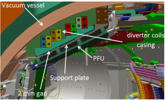
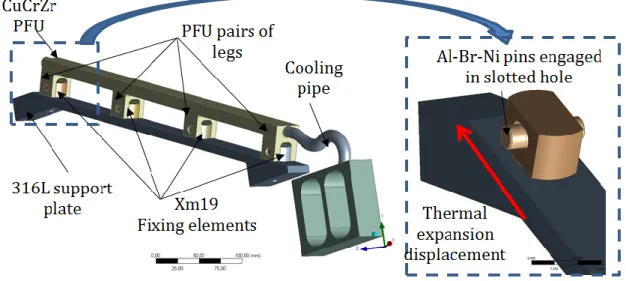
of the material of the PFU. The PFUs are fixed on the support plate thanks to 152 Xm19 stainless steel fixing elements (4 per PFU), and in each of this fixing element an Aluminium-Nickel-Bronze alloy (Al-Ni-Br) pin is engaged in a slotted hole, in order to allow thermal expansion in the length direction of the PFU (Fig. 2). The support plate is fixed at its edges on the divertor coil casing thanks to 10 M10 screws. The screws are made of stainless steel BUMAX 109 (equivalent to class 10.9 bolts). In the inner part of the support plate, five of the M10 screws are engaged in the casing. In the outer part of the support plate, the other five M10 screws are engaged to supporting bracket welded to the casing. There is a 2 mm gap between the central part of the divertor support plate and the divertor coil casing (Fig. 1 and 3).
Fig. 2. Structure of one PFU on the support plate (upper divertor)
Fig 3. the WEST divertor support plate
3
Structural analysis
The structural analysis was performed with ANSYS 16.0.
3.1 Design criteria
The design criteria for the support plate is 30 000 cycles in steady-state and 3000 cycles in VDE. According to the ITER material handbook [2], this corresponds to a maximal total strain (elastic strain+ plastic strain) for 316L stainless steel:
0,31% in steady states
0,54% in VDE
The design criterion for the screws in steady-states is the bolt preload, which should not be overcome by external forces. The preload is 32 500 N for M10 class 10.9 bolt according to AFNOR standards (85% of yield stress).
As VDE is a very brief event, preload overcome can be allowed. The design criterion for the screws in VDE is the von Mises yield criterion which should not be higher than the yield stress, which is 900 MPa for BUMAX 109. The von Mises stress is defined by √𝜎2+ 3𝜏2, where 𝜎 is the normal stress and 𝜏 the shear
stress.
3.2 Boundary conditions
The temperature of the WEST support plate is 70°C. The mechanical behavior of the support plate is elastoplastic. The mechanical behavior of the screws is elastic, as the von Mises yield criterion has to be respected.
Surfaces under the head of the screws are fixed (Fig. 3). Compression supports are used to represent the divertor coils casing Fig 5.
Fig 4. Fixed support under the heads of the screws
Fig 5. Compression support
3.3 Structural loads
As the fixing elements of the PFU allow displacement in their length direction, it is assumed that the forces acting on the PFU which are transmitted to the
support plate are always locally perpendicular to its top surface. The structural loads acting on the divertor support plate are of two kinds:
Loads due to thermal expansion of PFU
Electromagnetic loads (EM loads) acting directly on the support plate or acting on the PFU and transmitted to the PFU through the fixing elements
The loads due to thermal expansion of the PFU are more significant with the upper divertor, which is composed of CuCrZr heatsinks with a tungsten layer. These thermal expansion loads were always considered in order to be conservative. These loads were studied in [3]. These loads are the only ones in steady states.
During plasma disruption, the magnetic field inside the torus can vary rapidly. This will induce eddy current in the PFU or in the support plate. If the PFU assembled on the support plate are made of CuCrZr, the eddy current will first start to flow in the PFU because the electrical resistivity of CuCrZr (𝜌 = 2,10 ∙ 10−8 ohm.m
at 70°C) is much lower than the one of 316L stainless steel (𝜌 = 7,40 ∙ 10−7 ohm.m at 70°C). So the PFU will
generate a magnetic field opposite to the one that generated those eddy current, and will act as a magnetic screen for the support plate. If the PFU assembled on the support plate are made of graphite or tungsten monoblock, the eddy currents will first flow in the support plate which will act as a magnetic screen for the PFU. So during a plasma disruption, two configurations are possible:
If the PFU are made of CuCrZr, the eddy current flows in the PFU. The contribution of the magnetic field which is locally perpendicular to the PFU can be up to 90 T/s in upper position. This will induce a torque in the length direction of the PFU of 97 N.m [3].
If the PFU are made of tungsten monoblock or graphite the eddy current flows in the support plate. The contribution of the magnetic field which is locally perpendicular to the support plate can be up to 20 T/s in lower position. By using an internal CEA ANSYS APDL routine [4] an equivalent torque of 11 200 N.m was calculated (Fig. 6).
Fig 6. Disruption torque in the support plate
During a VDE the current flows through each PFU in the length direction because the plasma is in contact with the divertor [3,5]. Due to the toroidal contribution of magnetic field, which is 4.5 T, Halo forces are induced
in the PFU, perpendicular to its top surface. This force is always directed from the top surface of PFU to its legs. According to [5], the resulting force is -3,065 kN/PFU.
Seismic loads have not been considered since TORE supra is not a nuclear installation. Dead weight and magnet fast discharge loads have not been considered either. So they are three different load cases in total that can be seen in Tab 1:
Steady states VDE 1 VDE 2
Thermal expansion loads Thermal expansion loads + Halo forces + PFU disruption torque Thermal expansion loads + Halo force + support plate disruption torque Tab. 1: Load cases.
3.4 Structural Analysis
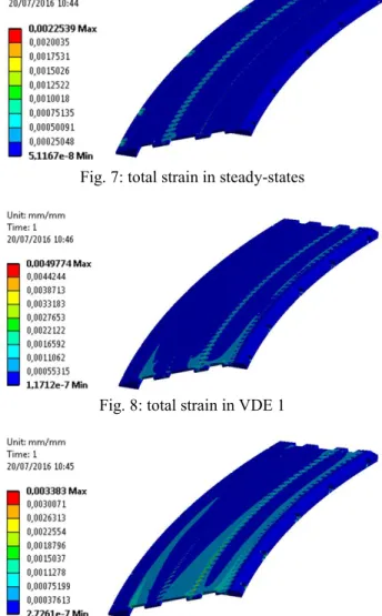
The simulations were run with ANSYS 16.0. The total strain in the support plate can be seen on Fig 7 to Fig 9 and are summarized in Tab 2. The total strain in the three load cases is always below the limits defined in part 3.1.
Fig. 7: total strain in steady-states
Fig. 8: total strain in VDE 1
Maximal total
strain Total strain
Steady-states 0,31 % 0,23 %
VDE 1 0,51 % 0,50 %
VDE 2 0,51 % 0,34 %
Tab. 2: Total strain in the three load cases In order to check the stress in the screws, the reactions forces from the fixed support under the head of the screws are used. A normal force 𝐹n and a radial force
𝐹r are extracted from these reaction forces. A friction
coefficient f of 0.5 is considered for the contact between the support plate on the divertor coil casings (in vacuum frictions forces are important). For the steady-states load case the equivalent preload 𝑃𝑒 can be calculated thanks
to the formula:
𝑃𝑒= 𝐹n+
𝐹r
𝑓
The equivalent section S of M10 screw is 58 mm². For the VDE load cases the von Mises stress 𝜎𝑒 can be
calculated thanks to the formula: 𝜎𝑒 =√(𝐹𝑆n)2+ 3(𝐹𝑆r)2
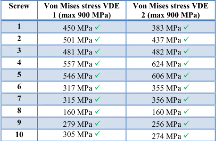
The preload in steady-states and the von Mises stress in VDE are below the limits described in part 3.1. The results of the 10 screws can be seen in Tab. 3 and Tab. 4.
Screw Equivalent Preload (max
32 500 N) 1 19432 N 2 15243 N 3 14830 N 4 15891 N 5 19478 N 6 24421 N 7 23511 N 8 23271 N 9 22332 N 10 23519 N
Tab. 3: equivalent preload in the screws in steady states
Screw Von Mises stress VDE
1 (max 900 MPa)
Von Mises stress VDE 2 (max 900 MPa) 1 450 MPa 383 MPa 2 501 MPa 437 MPa 3 481 MPa 482 MPa 4 557 MPa 624 MPa 5 546 MPa 606 MPa 6 317 MPa 355 MPa 7 315 MPa 356 MPa 8 160 MPa 160 MPa 9 279 MPa 256 MPa 10 305 MPa 274 MPa
Tab. 3: Von Mises yield stress in the screws in VDE
4
Conclusion
The structural integrity of the WEST divertor support plate was verified according the number of cycles defined in the WEST project: 30 000 cyclces in steady-states and 3000 cycles in VDE. The structural integrity of the screws fixing the support plate on the divertor coils casing was also verified: the preload was not overcome in steady-states and the von Mises yield criteria was respected in VDE. In this assessment the following load were considered: The most conservative thermal expansion loads of PFU expected during WEST operation in steady-states, and the eddy and halo current loads during disruptions and VDE. Seismic loads have not been considered since TORE supra is not a nuclear installation. Dead weight and magnet fast discharge loads have not been considered either.
5
References
[1] J. Bucalossi, M. Missirlian, P. Moreau, F. Samaille, E. Tsitrone, D. van Houtte, et al., The WEST project:
testing ITER divertor high heat flux component technology in a steady state tokamak environment,
ISFNT 2013, Fusion Engineering and Design, Volume 89, Issues 7–8, October 2014.
[2] ITER, Appendix A, Materials Design Limit Data v 3.3 reference IDM 222RLN
[3] T.Batal, M.Richou, D.Guilhem, M.Firdaouss, S.Larroque, F.Ferlay, M.Missirlian, J.Bucalossi,
Thermomechanical simulation of WEST actively cooled upper divertor
[4] Tristan Batal, Mehdi Firdaouss, Marianne Richou, Fabien Ferlay, Sébastien Larroque, Jérôme Bucalossi, et al, Design and manufacturing of WEST Baffle, SOFT 2014, Fusion Engineering and Design,
http://dx.doi.org/10.1016/j.fusengdes.2015.01.053. [5] S. Larroque, et al., The WEST project mechanical
analysis of the divertor structure according to the nuclear construction code, Fusion Eng. Des. (2014),