Compliant Modular Shape Memory Alloy Actuators
The MIT Faculty has made this article openly available.
Please share
how this access benefits you. Your story matters.
Citation
Torres-Jara, E. et al. “Compliant Modular Shape Memory Alloy
Actuators.” IEEE Robotics & Automation Magazine 17.4 (2010): 78–
87. Web. 30 Mar. 2012. © 2010 Institute of Electrical and Electronics
Engineers
As Published
http://dx.doi.org/10.1109/mra.2010.938845
Publisher
Institute of Electrical and Electronics Engineers (IEEE)
Version
Final published version
Citable link
http://hdl.handle.net/1721.1/69901
Terms of Use
Article is made available in accordance with the publisher's
policy and may be subject to US copyright law. Please refer to the
publisher's site for terms of use.
IEEE Robotics & Automation Magazine
78 1070-9932/10/$26.00ª2010 IEEE DECEMBER 2010
Composable Flexible Small Actuators
Built from Thin Shape Sheets
BY E. TORRES-JARA, K. GILPIN, J. KARGES, R.J. WOOD,
AND D. RUS
A
lternatives to traditional actuators, such as electromagnetic motors, are needed in applications where space and weight are limited, e.g., laparoscopic medical probes, miniature robotics, and micro-lens positioning systems. We present a family of small light-weight actuators that can be composed out of a basic unit cell to yield linear, rotational, and surface actuation. The unit cell actuator is built using shape memory alloy (SMA) sheets. It is activated by electrical current and the resultant heating. Depending on the combination of these unit cells, the designer can control the direction of actuation, the amount of force generated, and the expansion (stroke) of the actuator. The unit cell design overcomes Digital Object Identifier 10.1109/MRA.2010.938845limitations of actuators built with SMA wires. For example, the heat needed to activate the SMA is localized in a specific area by controlling the geometry of the electrical conduction path. This geometry is easily constructed by laser cutting the desired pattern. Additionally, the SMA can be mounted by its nonheating areas.
In this article, we characterize the new actuator, compare its performance with that of a traditional electromagnetic motor, and report on results of endurance tests. We also dem-onstrate a robotic system driven by these actuators.
We wish to develop printable robots constructed out of smart materials that embed actuation, computation, commu-nication, and sensing. We envision functional universality for printable robots by using new rapid fabrication techniques that embed function naturally within the device. In a classical sense, printing is a nominally two-dimensional (2-D) process involving deposition of materials onto a substrate. Although three-dimensional (3-D) rapid fabrication technologies exist and are quite mature for static structures, the development of technologies for embedding function within printed 3-D devices has not kept pace. The complex 3-D assembly of a func-tional robot can be alleviated by fabricating robots using nomi-nally 2-D multifunctional components that fold themselves into the desired 3-D shapes. Printable robots will know how to assemble themselves by having the assembly plans built into the structure along with actuation to carry out the plans.
An important challenge for printable robots is the actuation system. Actuators should be small, light, flexible, simple to fabri-cate, easy to integrate with surrounding materials, and capable of exerting high force. This article describes the development of actuators that satisfy these properties and can be used as alterna-tives to traditional actuators, such as electromagnetic motors. In general, motors require heavy magnetics, gearheads to exert high torque, rigidity to maintain internal alignment, and ample time to design and manufacture (e.g., skeletal muscle). In con-trast, a human muscle is light, flexible, and able to exert high forces directly.
Overcoming the differences between traditional electromag-netic motors and muscles requires approaching the problem with a different perspective. Biological systems present small actuators that are robust and flexible but produce small forces. The output forces from many actuators are combined to generate larger forces. In contrast, electromagnetic motors are enlarged or attached to a gearhead to increase their torque generated.
We describe an approach to designing composable actua-tors made out of small unit cells that is inspired by the hierar-chy of biological systems. Managing the fabrication and assembly of many small parts and mechanisms could be a daunting task. However, with current technology that enables the 3-D-printing of small structural designs, laser cutting of thin metallic sheets, deposition of metals onto a variety of sur-faces, and the precision etching of flexible circuits, we are able to overcome these manufacturing challenges with a relatively simple production process. Hopefully, this will lead to the cre-ation of fully printable actuators in the future.
More specifically, we have developed a family of small composable flexible actuators using thin SMA sheets. SMA is a
material that, in general, can exist in two states: martensite and austenite. In the martensite state, this material can be readily deformed. When heat is applied, SMA transitions to the aus-tenite state recovering its original shape. The force exerted by the material during this transition is the principle used in SMA actuators. SMA is advantageous for actuation because of its lightweight, silent operation, and flexibility. However, it is not easily scalable, and its power consumption is high. Our actuators overcome these limitations. Each unit cell of the actuator is small and light. It is activated by electrical current. Unit cell actuators can be composed to form linear, rotational, and surface actuators. Surface actuators are thin actuators that can be mounted to or embedded within a continuous surface to induce local curvature changes upon activation. The geom-etry of an assembly of unit cells determines the direction of actuation, the force generated, and the expansion (stroke) of the actuator. The actuators are capable of exerting high forces and can be powered from a battery [1]. For example, a proto-type linear actuator (Figure 1) composed of 24 unit cells weighs 0.5 g, requires 1.5 A, and consumes 6-W power. The actuator can lift 80 g, which is 160 times its weight.
Our work builds on several novel actuation systems that use SMAs (both wires and sheets) as soft actuators. For exam-ple, SMA springs wires were developed to increase the performance of SMA wire actuators [6]. The spring configura-tion was programmed by annealing the SMA wire. These spring actuators have been used to build robotic worms [6], microrobotic fish [5], and circular robots for crawling and jumping [7]. Control methods for wire SMA actuators have also been developed. For instance, SMA wires of different length were combined to control a robotic hand [2]. The stroke of the actuator was controlled by the activation pattern of the wires. The energy consumption of these actuators was improved by using thermoelectric modules. The effect of the SMA response time in the control has also been addressed in a biped robot [4]. Pulse width modulation has been used to reduce the energy consumption [8], [9]. Thin sheet actuators
Time
have been developed for small devices, such as microgrippers [3]. A major advantage of SMA sheets is that they can be cut using a laser, which simplifies fabrication.
Our work introduces a class of modular composable SMA actuation systems based on a flat SMA unit cell. In this article, in the “The Unit Cell” section, we describe the unit cell at the basis of our actuation system. We then show how many unit cells can be composed to form linear actuators, rotational actuators, and surface actuators in the “Composing Actuators” section. We proceed to show that our actuators have perform-ance comparable with that of a small electromagnetic motor and characterize the lifetime of the actuator in the “Endurance” section. Finally, we demonstrate that our actuators can be used to control the movement of a soft robot that rolls by deforming its geometry in the “Actuators in Practice: The HexRoller” section.
The Unit Cell
The unit cell is designed around a patterned SMA sheet. In general, SMA can exist in two states: martensite and austenite. In the martensitic phase, SMA is relatively easy to bend and
stretch. The application of heat triggers a phase transition to the austenitic phase causing the material to exert force as it attempts to return to a preprogrammed shape. This preprog-rammed shape can be set by annealing the SMA while fixing its shape as desired.
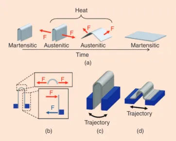
Our actuators are based on SMA sheets that naturally flatten when transitioning to the austenitic phase. Therefore, as illus-trated in Figure 2(a), heat will cause any bent regions to exert force as they attempt to reflatten. This force increases with curva-ture. As shown in Figure 2(b), we can mount a folded SMA sheet on the points between which we wish to apply force. Since the force generated by the unit cell is at the crease, we want to minimize the amount of material that is not folded, because this part of SMA is not doing useful work and, due to its limited thickness, is not rigid enough to effectively transmit force.
Two alternatives for mounting the unit cell are shown in Figure 2. The simplest method attaches the sides of the crease to a rigid structure [see Figure 2(c)]. Connecting the sides to the structure directly is preferred for circular motion, and this configuration works well for generating circular trajectories. The attachment shown in Figure 2(d) has two additional bends in the SMA that also contribute to the force generated. This configuration is more preferred for linear motion and is effective for generating linear trajectories. The two additional bends con-tribute to the generated force. We use this configuration for the unit cell [Figure 3(c)].
The unit cell activation is achieved by applying heat to the SMA to reach the transition temperatureðAfÞ of 95 °C. The SMA used is the Alloy H from Memory-Metalle GmbH. Instead of relying on an external heat source, our actuators are heated by the current passing through them. Because the creases are the regions that exert force, we increase their electrical resistance relative to the rest of the structure so that current heats the creases much more quickly than the remain-der of the structure. Figure 3(a) shows the pattern used to increase the electrical resistance of the creases. The SMA cell is heated up by passing an electrical current through it. The cell is built with a pattern that increases the electrical resistance in the regions where the sheet is bent. Due to their increased resistance, only the bent areas will heat up when current is applied. The remainder of the structure has less resistance and therefore heats up significantly less. These cooler regions can be used when mounting the cell. By folding this SMA sheet, we built the basic cell shown in Figure 3(b). The central crease bends 180°, and two side creases each bend 90°. Conse-quently, when the cell is fully expanded, it will be about 57% longer than its compressed configuration (assuming that there is no distance between the creases).
This unit cell design presents several advantages. The power needed to actuate the cell is reduced because only specific regions of the SMA material are heated. Additionally, the wider sections of SMA provide good structural mounting points, because they are stronger and do not deviate noticeably from room temperature. Finally, the nonheating sections of SMA provide heat sinking that allows the higher resistance areas to cool quickly once current is removed. This increases the effec-tive bandwidth of the actuator.
Heat F F F F F F F F
Martensitic Austenitic Austenitic Martensitic Time
(a)
(b) (c) (d)
Trajectory
Trajectory
Figure 2. (a) Observation of the response of a folded SMA sheet as it is heated. (b) Sectional view of a heated SMA folded sheet transmitting force to the blue structure. (c) The folded SMA sheet is connected to a structure to transmit the generated force. (d) The configuration preferred for linear motion.
l
(a) (b) (c)
Figure 3. (a) The cell built with a pattern that increases the electrical resistance in the regions where the sheet is bent. (b) The SMA pattern of (a) is bent to form the basic actuation cell. (c) The cell is mounted in a support structure so that it can exert force.
IEEE Robotics & Automation Magazine
It is important to note that the resting configuration of the SMA that we use to fabricate the cell is flat. When a folded unit cell is heated, it will try to become flat. However, it is also possible to program [6] the material so that its resting configu-ration is bent. In this case, when a flat cell is heated, it will try to reach its bent configuration, which will cause cell compres-sion instead of expancompres-sion. This can be done by annealing the SMA while in the bent configuration. The remainder of this article focuses on actuation systems using expanding cells built from an SMA sheet whose resting position is flat.
The Effect of Unit Cell Dimensions
We characterized the response of a given size actuator by measuring its force and displacement. The geometric pattern used to build a unit cell is shown in Figure 4(a), where the sec-tions of length d and d=2 are bent 180° and 90°, respectively. Accounting for these bends, the initial length of the bent region is x0¼ 4r ¼ 4d=p. Upon the application of heat, this cell expands to reach a size x1¼ 2d þ 2e. Consequently, its theoretical expansion is about 57% assuming the e can be disre-garded. In practice, this expansion is smaller, because the SMA performance degrades until it reaches a stable state.
The size of the unit cell has direct effect on its characteris-tics. To determine this relation, we built five actuators [Figure 4(c)] whose unit cells differ in size. Each actuator has six cells that are electrically connected in series [Figure 4(b)]. The dimensions of the cells are as follows: the thickness of the sheet is 0.063 mm, and its dimensions are: h¼ 0:25 mm, w¼ 1:75 mm, e ¼ 0:25 mm. Table 1 has the dimension d for
each actuator. Each of the three bends has a radius r¼ d=p. The displacement x and the force F are measured when the cell is locked.
Each of the five actuators was tested as follows. Each test began with the actuator in its fully expanded position. One side was mounted in a motion stage whose position was pre-cisely controlled using a stepper motor. The motion stage was moved so that the other side of the initially expanded actuator just barely came in contact with a load cell capable of measuring compressive force [see Figure 4(a)]. Then, we per-formed a series of three steps. First, the force exerted by the unheated actuator was measured. Second, we applied current to the actuator (1.8 A for 2.0 s) and measured the force again. Third, the actuator was allowed to cool for 20.0 s. After each iteration of this three-step measurement loop, we moved the motion stage closer to the load cell to further compress the actuator and repeated the same set of three steps for the new displacement. We continued this process until the actuator was fully compressed. By measuring the response of the tor when the SMA was inactive, we could discount the actua-tor’s natural spring effect.
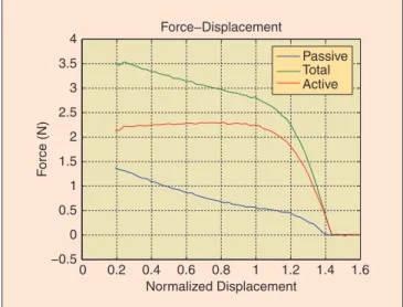
The response of the actuator with d¼ 1:2 mm is shown in Figure 5. The displacement is normalized with respect to the assumed initial position x0when the three bends measure 90°, 180°, and 90°, respectively [Figure 4(a)]. The active force is obtained by removing the passive force from the total force measured. In this plot, the normalized displacement is defined as the expansion divided by x0, the ideal initial configuration of the unit cell in which all three bends are multiples of 90° [Figure 4(a)]. In the upper plot of Figure 5, we observe the total force generated by the actuator and its passive response. The passive response of the actuator is similar to a linear spring. This passive response is due to the natural springiness of the bent SMA metal. The active force generated by the SMA is shown in the lower plot of Figure 5, where the passive com-ponent has been discounted. We observe that the force gener-ated by the actuator decreases rapidly as it expands past a normalized displacement of 1.0. In contrast, for relative
d /2 d d /2 h w r e x F (a) (b) (c)
Figure 4. (a) The pattern of one cell that is bent and mounted in a structure. (b) The actuators used for characterization have six unit cells connected electrically in series and mechanically in parallel. (c) Actuators assembled in the extended configuration.
Table 1. Cell size of each actuator.
Actuator d(mm) 1 0.6 2 0.9 3 1.2 4 1.5 5 1.8 0 0.2 0.4 0.6 0.8 1 1.2 1.4 1.6 −0.5 0 0.5 1 1.5 2 2.5 3 3.5 4 Normalized Displacement F orce (N) Force−Displacement Passive Total Active
Figure 5. Force–displacement response of actuator number 3ðd ¼ 1:2 mmÞ.
displacements less than 1.0, the force remains roughly constant. For displacements greater than one, the forces reduce rapidly. For system design purposes, we consider the unit cell an on/off actuator, which operates in the expansion region, and whose force depends on its maximum displacement.
Discounting the passive force, the active force generated at normalized displacement xnorm¼ 1 is 2:25 N. The maximum normalized displacement achieved is xnorm¼ 1:436.
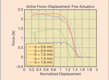
In Figure 6, we can observe the active force response of different sized actuators. As we increase the size of the cells, the generated force increases. This behavior reaches a peak around d¼ 1:2 mm; and as the size of the cell increases further, each generates less force. This can be attributed to the structural effects as explained in Figure 2(b). This shows that continuing to increase the amount of SMA in a unit cell does not continue
to generate more force. Instead, the force exerted by an actuator can be increased by combining multiple cells.
Electrical Resistance Response
The response of the cell to different values of electrical current was also tested. The response is shown in Figure 7, where we can observe the resistance change at least 15% of its initial value when the transition temperature is reached. The value of the resistance correspond to 24 cells (d¼ 1:2 mm) in series. The intensity of the electrical current affects the time taken to reach the transition temperature. In the case of 0.9 A, the transition temperature was not reached in the time window considered for the experiment.
Composing Actuators
In general, actuation mechanisms that work effectively in small dimensions but do not scale up well can be combined to obtain larger forces or displacements. Consider human muscle where the output force is generated by a combination of contractile proteins (myofilaments) connected in parallel and in series. We can do the same with the unit cells of our SMA actuators. The force exerted by a single unit cell does not scale up well, because the current required to heat thicker pieces of SMA becomes prohibitive. As shown in the “The Unit Cell: The Effect of Unit Cell Dimensions” section, increasing the length of the SMA beyond a certain point does not continue to produce larger forces either.
The alternative is to combine the output effects of multi-ple unit cells by mounting them in parallel and/or series to obtain different expansions, trajectories, and forces. The complexity of fabricating such actuators increases because many unit cells need to be mounted and controlled, but this additional complexity is more than offset by the flexibility offered in return. In many cases, the control of the unit cells can be simplified by separating them in groups. These groups of cells can be placed in a common electrical circuit for simultaneous activation.
Figure 8 shows different configurations of unit cells to cre-ate linear, rotational, and surface actuators. All the actuators in this figure use 24 unit cells, electrically connected in series. These unit cells are organized in 634 or 436 arrays that are mounted in different support structures to produce the desired trajectory. The array of unit cells was patterned with a laser on an SMA sheet (0:05 mm thickness) whose default position is flat. These actuators were built to operate in one direction. Bidirectional actuators can be achieved by using two or more actuators antagonistically.
Linear Actuator
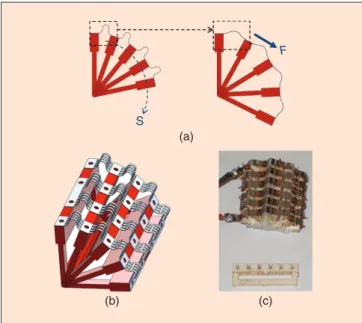
Figure 9(b) shows the idea used to build a linear actuator. Six cells are mounted on plastic hexagons that serve as support structures. Figure 9(a) illustrates the working principle; the six cells expand simultaneously on a linear trajectory. By mount-ing 24 unit cells on five hexagons (3-D printed), we build a four-stage linear actuator that is shown in Figure 9(c). This lin-ear actuator was operated with 1:5 A and 4 Vð6W. The maxi-mum output force measured is 80 gf ¼ 0:784 N. The 0 0.2 0.4 0.6 0.8 1 1.2 1.4 1.6 1.8 2 −0.5 0 0.5 1 1.5 2 2.5 Normalized Displacement F o rce (N)
Active Force−Displacement: Five Actuators
d = 0.6 mm d = 0.9 mm d = 1.2 mm d = 1.5 mm d = 1.8 mm
Figure 6. The active force–displacement response of the five actuators shows that for d <¼ 1:2 mm; the peak and average exerted force increases quickly with increasing d. For
d > 1:2 mm; the force begins to slowly drop off as d becomes progressively larger. The active force is obtained by discounting the passive force from the total force measured.
0 0.5 1 1.5 2 2.5 3 3.5 4 4.5 1.15 1.2 1.25 1.3 1.35 1.4 1.45 1.5 1.55 1.6 Time (s) SMA Resistance ( Ω )
SMA Resistance Versus Time Versus Driving Current 2.0 A 1.8 A 1.6 A 1.4 A 1.2 A 1.0 A
Figure 7. Current applied to the SMA was swept from 1.0 to 2.0 A to determine the response time of the SMA actuator as indicated by a change in its resistance. Higher currents produced quicker responses (less than 0.5 s).
IEEE Robotics & Automation Magazine
actuator weighs 0:5 g; consequently, its force to weight ratio is 1; 568 N=kg. This is equivalent to lifting 80 g with a weight of 0:5 g (160 times its weight disregarding the weight of the power supply).
One important feature of this actuator is its ability to follow trajectories that are not perfectly straight, because its operation does not require perfect alignment.
Rotational Actuator
A rotational version of the actuator can be realized by mounting the unit cell on a radial support structure as shown in Figure 10. Using this configuration, we have built a rota-tional actuator composed of 24 unit cells mounted on five radial support elements [Figure 10(c)]. This actuator was designed so that the angle formed by the first and last support elements changes from 90° to 180° upon activation. The support elements separate the center of rotation from the SMA attachment points by 6:5 mm. The SMA pattern used is identical to the one in the linear actuator described in the
“Composing Actuators: Linear Actuator” section. The fea-tures of this actuator are shown in Table 2. In this table, we have also included data from two electromagnetic motors of similar diameter (16 mm) for comparison purposes. In partic-ular, the rotational actuator weighs approximately 1/40th and 1/25th of the weight of the Micromo 1624006S and Maxon A2516 motors, respectively. It produces 3.4 and 6.7 times their torque and consumes 4.5 and 7.5 times as much as power. The ratio torque/power is comparable to the electromagnetic motor, whereas the ratio torque/weight is notoriously higher.
Surface Actuator
An array of unit cells can also be used to bend a flexible surface. This surface is shown in cross section in Figure 11(a), where the two different colors represent the rigid and flexible parts. The light color represents the flexible surface that is connected at several points to rigid elements. The unit cells are anchored on the rigid parts, and when they expand they bend the flexi-ble elements changing the surface curvature. We built a surface
Unit Cell
24 Cells Array (a)
(b)
Linear Rotational Surface
Figure 8. (a) SMA pattern that contains 24 unit cells electrically in series. (b) A unit cell array can be mounted in different support structures to produce different trajectories.
F
S
(a) (b) (c)
Figure 9. (a) Six unit cells expand simultaneously to generate a linear trajectory s. The force F is the summation of forces generated by each unit cell. (b) Perspective of a six unit cell actuator built on two hexagonal structures. (c) A four-stage linear actuator.
S
F
(a)
(b) (c)
Figure 10. (a) The unit cells, mounted on a radial structure, describe a circular trajectory s when expanding. (b) Perspective of a rotational actuator. (c) A rotational actuator and one of the elements used for the support structure.
Table 2. Electromagneticmotors/SMA actuator.
Units Micromo 1624006S Maxon A2516 SMA Actuator Diameter mm 16.00 16.00 13.00 Length mm 23.80 17.40 18.25 Torque mN.m 1.50 0.76 5.10 Power W 1.31 0.80 6.00 Weight g 21.00 12.40 0.50 Torque/ power mN.m/W 1.15 0.95 0.85 Torque/ weight mN.m/g 0.07 0.06 10.20
actuator using a 24 unit cell array. The support structure was printed on a 3-D printer that can produce flexible and rigid section within the same part (see the “Fabrication” section for details). This structure has seven rigid columns that support the six columns of four unit cells each. The actuator is shown in Figure 11(c) and is capable of generating a maximum torque of 3.0 mN.m when is flat.
Endurance
The lifetime of an actuator depends on several factors, e.g., the lifetime of the support structure, the heat profile applied to the SMA, the range of motion of the SMA, and the type of mounting mechanism used. In our case, we have tested the endurance of a 24 unit cell linear actuator mounted in a hexagonal structure as shown in Figure 9(c). This actuator
was built six months ago, and it has been in operation spor-adically since then.
To test the actuator endurance, we placed a weight on top of the linear actuator. We used a video camera and a potentiometer (which adds a frictional resistance of 13:5 gf ) to measure dis-placement. We conducted three experiments on three separate days. In the first experiment, the actuator was commanded to perform 300 extension operations with a 16:5-g weight. In the second experiment, the actuator was commanded to perform 1,000 operations, and its motion was videotaped every 100 itera-tions. In the third experiment, the actuator was commanded to do 10,000 lifting operations with a weight of 16:5 g. During this experiment, we used the potentiometer to measure displace-ment with higher resolution, which added a resistance of 13:5 gf . The actuator was opposing a force of 30:35 gf . After the three experiments, the actuator continues to be operational. Figure 12 shows the behavior of the actuator with the two different loads. The displacements were measured with a video camera and with a linear potentiometer, respectively. A 1.5-A current is applied to the actuator for 2 s. We can observe that as the temperature increases because of the current applied, the force generated increases as well. We observe that there is an initial period where there is no motion. In this period, the SMA is heating up. While it reaches its transition temperature, its generated force increases. Because of this, the different loads start their motion at different time: 60 ms and 83 ms, respectively, for the 16:85 g and 30:35 g. The load is lifted until the current is removed, at time 2 s; then the load compresses the actuator to its initial position. The load also lim-its the maximum displacement of the actuator.
This displacement decreases as the number of repetitions increase as shown in Figure 13. We can observe the average value and the standard deviation every 500 repetitions. The fatigue of the material is expected, because we are not control-ling the SMA temperature, and with repeated activation, the heat builds up in the creases and potentially alters the crystalline structure. After 10,000 repetitions with the 30:35-g load, we see that the actuator changed its maximum displacement from about 4:28 to 1:17 mm. For reference, we also plotted the data for 1,000 repetitions with the 16:85-g load. We observe that the standard deviation is quite similar and that we can expect a change of about 0:5 mm in the first 1000 repetitions.
Fabrication
The fabrication of the actuator consists of three parts: patterning of the SMA sheet, building of the support structure, and mounting. SMA Pattern
The SMA sheet is patterned using a diode-pumped solid-state laser that has a resolution of 10 lm. The thickness of the SMA used has been either 0:05 mm or 0:065 mm. The pattern cut has been designed to electrically connect in series a number of unit cells and to provide anchor points for mounting the cells to a support structure. The dimensions of one unit cell and a pat-tern of 24 unit cells are shown in Figures 4 and 8, respectively.
To electrically connect the ends of the SMA pattern, we typically use one of the two methods. In one, we crimp copper F
S
(a)
(c) (b)
Figure 11. (a) Sectional view of a surface composed of flexible and rigid parts. Unit cells are mounted on the rigid parts and upon activation, they bend the flexible parts changing the surface curvature following the trajectory s. (b) Perspective of a surface actuator partially bent. (c) A surface actuator with 24 unit cells arranged in six columns of four actuator each.
0 0.5 1 1.5 2 2.5 0 1 2 3 4 5 6 7 Time (s) Displacement (mm) Displacement−Time Mass = 16.85 g Mass = 30.35 g
Figure 12. Displacement of the linear actuator with different loads. The actuator is lifting 16.85 g (blue curve) and 30.35 g (red curve).
IEEE Robotics & Automation Magazine
foil around the SMA sheet and later solder a copper cable on it. In the other, we used screws and nuts to clamp the SMA against a copper terminal. Both methods work well, but crimp-ing the terminal is time consumcrimp-ing. We did not use direct sol-dering to the SMA, because the chemical treatment needed makes it impractical.
Support Structure
The hexagons used for the linear actuators (Figure 9) were 3-D printed with either one or two holes in each face, depending on whether the SMA was anchored with bolts or wire. The print-ers used were Stratasys Prodigy Plus FDM 3-D or Objet Con-nex 500. The hexagons sides were each 4-mm long. The hexagons have an opening in their center to mount the actuator on a guide rod if required. This guide can have some curvature, because the actuation mechanism does not rely on alignment.
The rotational actuator uses 16 mm36:5 mm rectangles as support structures (Figure 10). These rectangles are all bound together at the center of rotation. These elements were built by gluing together three layer of cardboard (0:54-mm thick) that were patterned on a laser cutter (VersaLASER).
The structure used for the surface actuator (Figure 11) was 3-D printed on an Objet Connex 500 that can create parts using two types of materials. The rigid material was Vero-White, and the rubber material was Tangoþ shore 50. The height of the structure (2:74 mm) is small and can be consid-ered a thick plane. As in the linear actuator case, the rigid parts have either one or two holes for SMA mounting purposes. Mounting
Mounting the SMA on the support structure was the most time-consuming step in the actuator manufacturing process. Our first method to attach the SMA to a structure was stitch-ing the two together with 34 gauge copper wire. The wire was threaded through two holes in both the SMA and the sup-port structure and then tied with a square knot on top. This process was very time consuming as each stitch took at least 4 min to complete. A few failure modes include the wire snap-ping because of axial tension during activation or fabrication, the knot becoming untied because of inconsistent stitching, and the wire cutting completely through the plastic support structure creating a slot instead of two holes. We have improved the mounting by using 0:5 mm, hexagonal head bolts that self-tap into the plastic support structures. Because the bolts are so small, it is easy to strip the hex head with the hex driver, rendering the bolt unable to be tightened without the use of minipliers. The threads in the plastic, which the bolt creates for itself, can also be subject to stripping since the threads are so small and so close together. To date, we have had few problems with either the head or the threads stripping. Our only recorded failure occurred when we applied too much current and melted the plastic support material sur-rounding the bolt.
Actuators in Practice: The HexRoller
To show that our actuators can be easily and reliably used in practical systems, we built the six-module autonomous chain
robot shown in Figure 14 that we call the HexRoller. The rigid links of the robot are printed circuit boards (PCBs) con-taining the circuitry necessary to control the joints—each of which is a surface-type SMA actuator. For reference, the total weight of the HexRoller is 85 g; it is 9 cm in diameter and 4-cm wide.
Using a closed-loop distributed controller running at 10 Hz on each of the six modules, we performed experi-ments to characterize both the HexRoller’s speed and reli-ability. At any given time, there are always two actuators that are activated—the actuator resting on the ground near-est the direction of motion and the actuator directly opposite to it. For example, if the actuators are numbered sequen-tially, the actuation sequence goes Acts 1 and 4, followed by Acts 2 and 5, followed by Acts 3 and 6, followed by Acts 4 and 1, etc. In the speed test, the HexRoller moved 27:94 cm
−2,0001 0 2,000 4,000 6,000 8,000 10,000 2 3 4 5 6 7 Repetitions Displacement (mm) Displacement−Repetitions Mass = 30.35 g Mass = 16.85 g
Figure 13. The figure shows the displacement of the actuator for 10,000 repetitions with a load of 20.35 g and for 1,000 repetitions with a load of 16.85 g. The average displacement and the standard deviation every 500 repetitions are shown. The configuration used is the same as the one described in Figure 12.
(a) (b)
Figure 14. (a) The HexRoller is an autonomous chain-type robot consisting of six PCBs. Each one controls an actuator and is powered by onboard batteries. These modules communicate via a flexible circuit. (b) The actuator has a rubber and plastic base with 24 SMA unit cells.
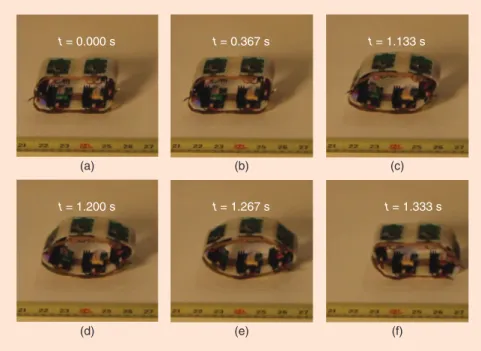
in 9 s for a speed of 3:1 cm=s. During this time, it executed six steps or one step every 1:5 s. Select frames from this rolling sequence are shown in Figure 15, where t¼ 0:000 s was chosen arbitrarily.
We tested the reliability of the actuators by allowing the HexRoller to step until it stopped on its own. In five tests, the robot was able to take 32, 12, 16, 16, and 48 steps, respec-tively, before it was unable to keep moving. In three of these cases, (the first, fourth, and fifth), a software bug causing one of the modules to lock up was responsible for the robot’s ulti-mate halting. Also, it should be noted that the robot per-formed the 32- and 48-step sequences, when its batteries were fully charged. The 12- and 16-step sequences were all performed in quick succession after the 32-step sequence. The HexRoller demonstrates several important features of our new actuators. First, the actuators can be powered by batteries. A 3:7-V lithium-polymer battery rated for 130 mAh is attached to each module in the chain. Using a flex circuit, these six bat-teries are wired into three parallel groups, each group contain-ing two batteries in series. This results in a combined output of 7:4 V rated for . While these batteries cannot power the Hex-Roller indefinitely, the 48-step sequence mentioned above demonstrates that a single charge can supply current for at least 96 actuations. It is worth noting that the HexRoller drives each of SMA pieces with a linear regulator that dissipates a significant amount of energy as heat. With a switched controller, we would expect to see a noticeable increase in battery life.
Second, the HexRoller demonstrates that the SMA actua-tors exhibit relatively fast relaxation times. The speed test showed that the robot moved at 1.5 steps per second. Given that the actuators are always used in tandem to make each step, each actuator only had 3 s to cool down before it was ener-gized again. Moreover, in the (1:5 s long) step immediately after
each actuator is activated, the geometry of the HexRoller forces it to morph from its energized flat shape back to its natural curved configuration. In other words, the actuators are able to transi-tion from relaxed, to activated, back to relaxed in less than 3 s.
Finally, our experiments with the Hex-Roller show that the SMA actuators are robust. During the reliability test, each of the six SMA pieces was actuated over 40 times. From the first experiment to the last, the HexRoller showed no degradation in performance. These 40 cycles are in addi-tion to many more that were performed while refining the low-level software and high-level control algorithm. Unlike lin-ear SMA actuators based on single strands of SMA wire, which may degrade in performance when subject to even mod-erate strains, our surface actuators are able to withstand near 360° bending over many cycles.
Conclusion
We have presented a simple but effective method to design flexible actuators. This process relies on understanding the behavior of a simple unit cell element built out of SMA sheet. The unit cell effectively uses the properties of flat SMA sheets: it operates in the bent region where more force is generated; it minimizes the nonbent SMA; and it heats up only the bent regions. However, the force generated by this unit cell does not scale up well, and an array of them is needed to increase the force generated. Building an actuator out of an array of unit cells increases its complexity but pro-vides advantages, including the control of expansion length, trajectory, and generated force. Given the current technolo-gies, including 3-D printing and laser cutting, a variety of support structures can be built to create an actuator with a given behavior. We have shown three types of configura-tions: linear, rotational, and surface. The linear actuator has been tested for endurance and can easily perform over 10,000 repetitions under load without breaking. These actuators have been tested in actual systems, such as the bat-tery-operated HexRoller robot that uses six actuators con-nected in a chain. The robot demonstrates that this SMA actuator is power efficient compared with other SMA designs that cannot operate with batteries. We have also showed that a rotational version of this type of actuator is comparable with an electromagnetic motor.
These actuators are light and small because of their constit-uent materials. Their support structure can be built with flexi-ble materials for applications that require deformability. They can be designed to follow complex trajectories that are difficult to achieve with traditional technologies. The actuators fabrica-tion process is simple and could be fully automated to have printable actuators. These features make these actuators a
(a) (b) (c)
(d) (e) (f)
t = 0.000 s t = 0.367 s t = 1.133 s t = 1.200 s t = 1.267 s t = 1.333 s
Figure 15. This sequence of frames shows the most significant events as the HexRoller takes one step from (a)–(f).
IEEE Robotics & Automation Magazine
promising alternative to traditional technologies in current and new robotics applications.
Acknowledgments
This work is supported in part by Defense Advanced Research Projects Agency (DARPA) grants W911Nf-08-1-0228 (Pro-grammable Matter) and W911NF-08-C-0060 (Chemical Robots). The authors thank Ara Knaian for facilitating the test rig used to determine the force response of the actuators.
Keywords
actuation, compliant robots, multifunctional structures, shape memory alloy, flexible actuators.
References
[1] E. R. Torres-Jara and D. Rus, “Flexible actuator based on shape memory alloy sheet,” U.S. Patent Application 12/896 184, Oct. 1, 2010.
[2] K.-J. Cho, J. Rosemarin, and H. Asada, “Design of vast DOF artificial muscle actuators with a cellular array structure and its application to a five-fingered robotic hand,” in Proc. 2006 IEEE Int. Conf. Robotics and Automa-tion (ICRA’06), May 15–19, 2006, pp. 2214–2219.
[3] M. Leester-Sch€adel, B. Hoxhold, C. Lesche, S. Demming, and S.
B€uttgenbach, “Micro actuators on the basis of thin SMA foils,” Microsyst.
Technol., vol. 14, no. 4, pp. 697–704, Feb. 27, 2008.
[4] E. T. Esfahani and M. H. Elahinia, “Stable walking pattern for an SMA-actuated biped,” IEEE/ASME Trans. Mechatronics, vol. 12, no. 5, pp. 534– 541, Oct. 2007.
[5] K.-J. Cho, E. Hawkes, C. Quinn, and R. J. Wood, “Design, fabrication and analysis of a body-caudal fin propulsion system for a microrobotic fish,” in Proc. IEEE Int. Conf. Robotics and Automation (ICRA’08), May 19–23, 2008, pp. 706–711.
[6] S. Kim, E. Hawkes, K. Choy, M. Joldaz, J. Foley, and R. Wood, “Micro artificial muscle fiber using NiTi spring for soft robotics,” in Proc. IEEE/ RSJ Int. Conf. Intelligent Robots and Systems (IROS) 2009, Oct. 10–15, 2009, pp. 2228–2234.
[7] Y. Sugiyama, A. Shiotsu, M. Yamanaka, and S. Hirai, “Circular/spherical robots for crawling and jumping,” in Proc. 2005 IEEE Int. Conf. Robotics and Automation (ICRA’05), Apr. 18–22, 2005, pp. 3595–3600.
[8] C. S. Loh, H. Yokoi, and T. Arai, “New shape memory alloy actuator: Design and application in the prosthetic hand,” in Proc. 27th Annu. Int. Conf. Engineering in Medicine and Biology Society (IEEE-EMBS’05), Jan. 17– 18, 2006, pp. 6900–6903.
[9] M. Ma and G. Song, “Control of shape memory alloy actuator using pulse width modulation,” Smart Mater. Struct., vol. 12, no. 5, p. 712, 2003.
E. Torres-Jaracompleted his M.S. degree in electrical engi-neering and Ph.D. degree in computer science at Massachu-setts Institute of Technology (MIT). His thesis work was conducted in Computer Science and Artificial Intelligence Laboratory (CSAIL) at MIT, where he developed sensitive manipulation, an approach to robotic manipulation based on tac-tile feedback. Currently, he is an assistant professor in Robotics Engineering Program at Worcester Polytechnic Institute (WPI). His current research interests include sensitive manipulation, compliant actuation, tactile sensing, and microfabrication. K. Gilpinreceived his B.S. degree in electrical engineering and M.Eng. degree in computer science at MIT. Then, he worked as a senior electrical engineer at Proteus Biomedical for two years, developing ultra-low-power hardware and soft-ware for several implantable personalized medicine products.
He is currently a Ph.D. candidate in Distributed Robotics Laboratory at MIT. He works to improve communication and control in large distributed robotic systems. His past projects include developing ultra-wideband radios, real-time image-processing systems, reconfigurable sensor nodes, chain robots with compliant actuators, and a collection of 12-mm cubes capa-ble of shape formation through self-disassembly. He was awarded both National Science Foundation (NSF) and National Defense Science and Engineering Graduate fellowships.
J. Kargesreceived his B.S. degree in mechanical engineering from MIT. He is currently a master’s student in robotics at the University of Pennsylvania. His past projects include develop-ing a lightweight portable braille labeler called 6Dot, designdevelop-ing fingertip molds for innovative tactile sensors, and designing and fabricating a foldable laser projector system driven by step-per motors.
R.J. Woodcompleted his M.S. degree in 2001 and Ph.D. degree in 2004 from the Department of Electrical Engineering and Computer Sciences at the University of California, Berke-ley. He is an associate professor in Harvard’s School of Engi-neering and Applied Sciences and a core faculty member of Wyss Institute for Biologically Inspired Engineering. He is the founder of Harvard Microrobotics Laboratory. He is also the winner of 2007 DARPA Young Faculty Award, 2008 NSF Career Award, 2008 Office of Naval Research Young Investi-gator Award, 2008 Air Force Young InvestiInvesti-gator Award, multiple best paper and best video awards, and a member of the 2008 class of technology review’s TR35. In January 2010, he received the Presidential Early Career Award for Scientists and Engineers from President Obama. His research interests include creation of biologically inspired aerial and ambulatory microrobots, unsteady aerodynamics of flapping-wing flight, minimal control of underactuated computation-limited sys-tems, decentralized control of multiagent syssys-tems, artificial muscles, and morphable soft-bodied robots.
D. Rus earned her Ph.D. degree in computer science from Cornell University. She is a professor of electrical engineering and computer science, where she is an associate director of MIT’s CSAIL and codirects the MIT Center for Robotics at CSAIL. She is the recipient of the NSF Career Award and an Alfred P. Sloan Foundation Fellow. She is a Class of 2002 Mac-Arthur Fellow and a Fellow of the Association for the Advance-ment of Artificial Intelligence and IEEE. Before receiving her appointment at MIT, she was a professor in the Computer Sci-ence Department at Dartmouth, where she founded and directed two laboratories in robotics and mobile computing. Her research interests include distributed robotics and mobile computing, transportation, security, environmental modeling and monitoring, underwater exploration, and agriculture. Address for Correspondence: E. Torres-Jara, Computer Science and Artificial Intelligence Lab., Massachusetts Institute of Technology, Cambridge, 32 Vassar St., Room 32-379, MA, 02139 USA. E-mail: [email protected].