HAL Id: hal-01348780
https://hal.archives-ouvertes.fr/hal-01348780
Submitted on 25 Jul 2016
HAL is a multi-disciplinary open access
archive for the deposit and dissemination of
sci-entific research documents, whether they are
pub-lished or not. The documents may come from
teaching and research institutions in France or
abroad, or from public or private research centers.
L’archive ouverte pluridisciplinaire HAL, est
destinée au dépôt et à la diffusion de documents
scientifiques de niveau recherche, publiés ou non,
émanant des établissements d’enseignement et de
recherche français ou étrangers, des laboratoires
publics ou privés.
Two-Phase Pipe Flow in Microgravity with and without
Phase Change: recent progress and future prospects
Marine Narcy, Catherine Colin
To cite this version:
Marine Narcy, Catherine Colin. Two-Phase Pipe Flow in Microgravity with and without Phase
Change: recent progress and future prospects. Interfacial Phenomena and Heat Transfer, Begell
House, 2015, 3 (1), pp.1-17. �10.1615/InterfacPhenomHeatTransfer.2015012413�. �hal-01348780�
O
pen
A
rchive
T
OULOUSE
A
rchive
O
uverte (
OATAO
)
OATAO is an open access repository that collects the work of Toulouse researchers and
makes it freely available over the web where possible.
This is an author-deposited version published in :
http://oatao.univ-toulouse.fr/
Eprints ID : 15903
To link to this article : DOI:10.1615/InterfacPhenomHeatTransfer.2015012413
URL:
http://dx.doi.org/10.1615/InterfacPhenomHeatTransfer.2015012413
To cite this version : Narcy, Marine and Colin, Catherine Two-Phase
Pipe Flow in Microgravity with and without Phase Change: recent
progress and future prospects. (2015) Interfacial Phenomena and Heat
Transfer, vol. 3 (n° 1). pp. 1-17. ISSN 2169-2785
Any correspondence concerning this service should be sent to the repository
administrator:
[email protected]
TWO-PHASE PIPE FLOW IN MICROGRAVITY WITH
AND WITHOUT PHASE CHANGE: RECENT PROGRESS
AND FUTURE PROSPECTS
Marine Narcy & Catherine Colin
∗Institut de M´ecanique des Fluides de Toulouse, Universit´e de Toulouse (INP-CNRS),
All´ee Camille Soula, 31400 Toulouse, France
∗Address all correspondence to Catherine Colin, E-mail: [email protected]
Gas-liquid and liquid-vapor pipe flows in microgravity have been studied for more than forty years because of theirpo-tential applications in space industries for thermal control of satellites, propellant supply for launchers, and wastewater treatment for space missions. Also, microgravity experiments provide unique conditions for highlighting and modeling capillary and inertia effects in the dynamics of two-phase flows. This paper discusses the results of flow pattern char-acterization, void fraction measurements, wall and interfacial shear stresses, and heat transfer coefficients. The main results are compared with ground experiments and classical correlations and models from the literature. Recent results from flow boiling in pipes are also discussed and perspectives on future studies are presented.
KEY WORDS: two-phase flow, flow boiling, microgravity, wall friction, heat transfer
1. INTRODUCTION
Gas-liquid and vapor-liquid flows play a role in a wide variety of applications in environments of both normal and reduced gravity. As is usually the case, there are many benefits and drawbacks to the use of two-phase systems, and consequently serious consideration must be given to whether or not to proceed with the design, construction, and use of these systems, particularly in reduced-gravity conditions.
In normal-gravity, or terrestrial, applications, gas-liquid flows have been traditionally studied by the petroleum and nuclear industries. The petroleum industry has focused most of its efforts on flow through long pipelines to transfer a mixture of crude oil and natural gas from a well and then separate the components or products of the flow at the refinery. The nuclear industry has focused on system stability and safety with the primary intent of preventing dry-out of the nuclear reactor through either heat transfer/fluid flow instability or loss of coolant as the heat energy is transferred from the reactor to the turbines. The chemical industry has utilized gas-liquid contactors to increase interfacial heat and mass transfers in absorption, stripping, and distillation processes that involve two-phase flow though complex geometries.
In a reduced-gravity environment, the principles of two-phase flow remain the same. Applications include thermal management systems for satellites, power management systems for long-term missions or manned space platforms, and management of fluid from the storage tanks of launchers through the lines to the engine. Thermal management systems transfer heat from a source (resistance heat from electronic equipment) to a sink, typically through a radiator panel. Different devices are used depending on the power to be transferred: heat pipes, loop heat pipes, single-phase mechanical pumped loops, and so forth.
Future communications satellites will require heat removal capabilities greater than 10 kW. In this context, the use of a two-phase mechanical pumped loop significantly reduces weight and size through powerful heat transfer by latent heat. However, up to now technical solutions involving single-phase mechanical pumped loops have often been preferred because of the lack of reliable predictive models for sizing two-phase flow loops. Nevertheless, in the future the use of two-phase mechanical pumped loops will become unavoidable for thermal management and for power
NOMENCLATURE
Bo Boiling number (—) We Weber number (—)
D tube inner diameter (m) x quality (—)
e liquid droplet entrainment (—) z axial coordinate (m)
f friction factor (—) a void fraction (—) Fr Froude number (—) δ liquid film thickness (m)
g gravity acceleration (m/s2) λ thermal conductivity (W/m2/K)
G mass flux (kg/m2/s) ρ density (kg/m3)
h heat transfer coefficient ν kinematic viscosity (m2/s) (W/m2/K) σ surface tension (N/m)
j superficial velocity (m) τ shear stress (Pa) Oh Ohnesorge number (—) G gas
P pressure (Pa) i interfacial Pr Prandtl number (—) L liquid Re Reynolds number (—) V vapor
U mean velocity (m/s) w wall
generation (from nuclear reactors) for long-term space missions and wastewater treatment. To properly design such systems under microgravity conditions, it is necessary that flow pattern, pressure drop, heat transfer, and critical heat flux (CHF) be predicted.
Another important problem concerns fluid management—the behavior of the propellant in the launcher tanks and its transfer from the tank to the engines through supply lines. Cryogenic liquids are pressurized by their vapor or a noncondensable gas. During the different phases of the mission (propelled, ballistic), it is important to control phase distribution and the evolution of temperature and pressure inside the reservoirs. The evolution of these parameters strongly depends on heat and mass transfer. During the ballistic phase of a mission, the tank wall is heated by solar radiation and thermal dissipation from the engine and electrical devices. Because there is no thermal convection in microgravity, heat transfer between the heated wall and the liquid is mainly due to heat conduction, and the wall temperature can become greater than the required temperature for the onset of nucleate boiling. For this reason, the study of boiling in microgravity is of particular interest.
Boiling is a complex process that combines heat and mass transfer, hydrodynamics, and interfacial phenomena. Because gravity affects the fluid dynamics of boiling and may lead to unpredictable performance of thermal man-agement systems, it is necessary to perform experiments directly in (near) weightless environments. Besides the International Space Station, microgravity conditions can be simulated by means of a drop tower and parabolic flights onboard an aircraft or a sounding rocket. This review focuses on both older and recent results obtained in microgravity for gas-liquid flow or flow boiling in pipes for wall heat fluxes lower than the critical heat flux.
In the past forty years, many gas-liquid flow experiments have been conducted in microgravity conditions. Space applications have raised some classical technical problems that have stimulated two-phase flow research. Among these are predictions of flow pattern; pressure drop; heat transfer, including critical heat flux; and void fraction in thermohydraulic systems. Beyond the design of space systems, reduced-gravity two-phase flows can address some fundamental questions that remain unsolved. On earth, the force balance between the two phases is often dominated by gravitational force. As gravity is suppressed, a new balance comes into play between inertial, viscous, and interfacial forces so that the mechanics governing the interactions between phases drastically change. Low-gravity conditions are particularly favorable to the emergence of surface tension as a dominating force whose role is often small in 1-g environments.
In the following, we focus on the main results concerning flow pattern, void fraction distribution, pressure drop in adiabatic gas-liquid flow and/or vapor-liquid flows in microgravity in pipe flows, and heat transfer coefficients (HTC) in vapor-liquid flows. Because this review is not meant to be exhaustive, the reader is directed to complementary information that can be found in Colin et al. (1996); McQuillen et al. (1998); Ohta (2003); Celata and Zummo (2009); Zhao (2010); and Ohta and Baba (2013).
2. FLOW PATTERNS AND TRANSITIONS
The classification of two-phase flow by various patterns, although subjective, is easy to accomplish because it requires careful observation of the flow only; similar patterns are observed for gas-liquid (adabatic) flows and vapor-liquid (boiling) flows. Several studies with and without phase change have been carried out in microgravity conditions over the past 30 years. The fluids used were either air and water or boiling CFC-12, 113, 114; FC-72; or HFE-7000. Studies performed in the 1990s and early 2000s mainly concerned gas-liquid adiabatic flows, in tubes of 6–40-mm inner diameter, and flow pattern maps were classically plotted versus the superficial velocities of liquid jLand gas jG
(Dukler et al., 1988; Colin et al., 1991, 1996; Huckerby and Rezkallah, 1992; Zhao and Rezkallah, 1993; Bousman et al., 1996; Zhao et al., 2001).
At a low void fraction, bubbly flow occurs. At high jL and low jG values, small bubbles of a few millimeters
appear that are nearly spherical. Their motion is rectilinear with nearly the same velocity, and their size is mainly controlled by coalescence. As the void fraction increases, larger bubbles are created.
Large bubbles are the precursors of cylindrical bubbles that appear in slug flow at higher void fractions. These have a smooth interface and a spherical nose and are separated by liquid slugs. The slugs contain smaller spherical bubbles moving at nearly the same velocity as the cylindrical bubbles. In contrast to 1-g upward flow bubbles, these bubbles are not created by gas entrainment at the rear of the cylindrical bubbles; rather, they are simply the residues of the initial bubbles injected at the inlet section of the tube.
As gas velocity increases, the liquid slugs decrease in length; when they are short enough, they collapse. The resulting pattern, consisting of liquid flowing in the form of a film at the wall and gas flowing in the center, is similar to annular flow. The gas core can sometimes break up, causing the appearance of frothy slugs containing many small bubbles. This flow pattern, which is often called frothy slug annular flow (Zhao and Rezkallah, 1993), is a transition between slug flow and annular flow, which occurs at the highest gas superficial velocities. When the gas velocity is very high, the interface becomes wavy and some droplets can be entrained in the gas core.
Determining a flow pattern is sometime subjective and is not a final goal. However, modeling wall shear stress and wall heat transfer depends on flow patterns and particular attention must be paid to determining the transition between them.
Different models exist for predicting the transition from bubbly to slug flow. Some of them are based on a critical value of the void fraction αc(Dukler et al., 1988; Colin et al., 1991) or a critical value of the Weber number (Zhao and
Rezkallah, 1993). The transition from bubbly to slug flow is very progressive, with an increase in bubble size resulting from a coalescence mechanism along the tube. For gas-liquid (Dukler et al., 1988; Colin and Fabre, 1995; Bousman et al., 1996; Colin et al. 1991) and liquid-vapor flows (Reinarts, 1993), two coalescence regimes have been identified: inhibiting and promoting. Colin et al. (1996) pointed out that these regimes are characterized by the Ohnesorge number, Oh = νL√ρL/σD based on liquid properties (density, viscosity, surface tension) and tube diameter D. In
the inhibiting coalescence regime for Oh > 8.2 × 10⁻⁴, the transition between bubbly and slug flows occurs for αc≈
0.45; in the promoting coalescence regime for Oh < 7.6 × 10⁻⁴, the transition occurs for αc≈ 0.2. A criterion based
on the Suratman number Su = 1/Oh2was proposed by Jayawardena et al. (1997).
Because the transition from bubbly to slug flow is due to bubble coalescence, it seems relevant to develop mecha-nistic models of bubble coalescence in turbulent pipe flows. To validate these models, several authors measured bubble size evolution along the pipe (Takamasa et al., 2003; Kamp et al., 2001; Colin et al., 2008; Hazuku et al., 2012). Kamp et al. (2001) proposed a model to predict the rate of bubble coalescence in a turbulent flow and were able to reproduce the evolution of bubble size along a 40-mm-diameter tube. They found that coalescence is promoted by turbulence when the bubble size is smaller than the turbulence integral length scale (typically D/4, D being the tube diameter). When the bubble size is larger than the turbulence integral length scale, turbulence is no more efficient in promoting
coalescence. The source of bubble collision and coalescence is the mean shear of the flow (Colin et al., 2008), and the coalescence rate is much smaller. The ratio of bubble size to tube diameter is the parameter that distinguishes the two coalescence regimes. Zhao (2005) proposed a criterion for the void fraction at the transition between bubbly and slug flow based on the ratio of initial bubble diameter to tube diameter. However, this ratio cannot be the only parameter; the length of the tube also has to be taken into account to predict bubble size evolution along the pipe by coalescence. Different authors have studied the transition from slug to annular flow, including Dukler et al. (1988), Huckerby and Rezkallah (1992), and Bousman and Dukler (1994). Based on experimental results, different approaches for the prediction of this transition have been proposed. According to Dukler et al. (1988), for turbulent gas and liquid flows the transitional void fraction calculated from both slug flow and annular flow models must be equal and thus is determined by α5/2 (1 − α)2 = fi fw ρG ρL µ jG jL ¶2 (1)
where fiand fware the interfacial and wall friction factors and jG and jLare the gas and liquid densities. Dukler
et al. found a transition between slug and annular flow for a void fraction value α ≈ 0.8. The value of the critical void fraction at the transition calculated by Eq. (1) is very sensitive to the modeling of the wall and interfacial friction factors (Zhao, 2010), so care must be taken in using this model.
Zhao and Rezkallah (1993) assumed that the transition between slug and annular flow occurs at a critical value of a Weber number, the ratio of gas inertia to capillary effects: WeGS = ρGjG2D/σ ≈ 20. Zhao and Hu (2000)
proposed a model for predicting the transition between slug and annular flow in microgravity. Their approach was similar to Reinarts’ (1993), assuming that transition occurs when the impulsive force due to gas inertia is sufficient to overcome the surface tension force that maintains the spherical shape of the nozzle of the elongated bubbles. This model seems to be able to reproduce the transition observed for air-water flows in microgravity, liquid-liquid flows in normal gravity, and air-water flows in small tubes in normal gravity. However, it is sensitive to the values of the distribution parameter C0in slug flow and to an adjustable constant that is chosen to fit the experimental data.
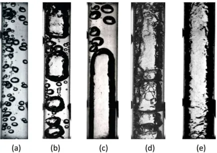
The same flow patterns—bubbly, slug, and annular (Fig. 1) are observed in adiabatic gas-liquid flows, condensing flow, and convective boiling for wall heat fluxes smaller than the critical heat flux (Ohta, 1997, 2003; Reinarts, 1993;
FIG. 1: Flow visualizations of boiling HFE-7000 in a 6-mm-diameter tube (Narcy, 2014): (a) bubbly flow: G = 61 kg/s/m2, ∆Tsub = 11◦C, q = 1.1 W/cm2; (b) transition bubbly-slug flow: G = 50 kg/s/m2, ∆Tsub = 9◦C, q =
2 W/cm2; (c) slug flow: G = 202 kg/s/m2, ∆Tsub = 4◦C, q = 1.1 W/cm2; (d) transition slug-annular flow: G =
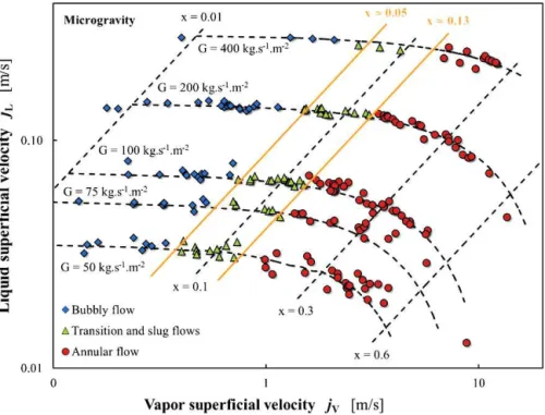
Celata and Zummo, 2009; Narcy et al., 2014a). Transitional flows, such as bubble-slug and slug-annular, are also observed. The main difference between adiabatic and boiling flows is the nucleation of the bubbles at the wall and the constant evolution of quality and void fraction along the heated tube. Ohta (2003) studied flow boiling of R-113 in a vertical transparent tube of 8-mm internal diameter coated on the inside with a gold film, and observed bubbly, slug, and annular flows. Celata and Zummo (2009) performed experiments in parabolic flights with boiling FC-72 in Pyrex tubes of 2-, 4-, and 6-mm diameters. They observed bubbly, plug, and disordered intermittent flow and plotted a flow pattern map versus the mass flux G and the thermodynamic quality (negative in subcooled boiling), showing that it is difficult to compare subcooled boiling with the classical flow pattern map established for air-water flow. Recently, Narcy et al. (2014a) studied flow boiling in a sapphire tube of 6-mm diameter coated on the outside with an ITO deposit heated by the Joule effect. They used the vapor and liquid superficial velocities to plot a flow pattern map. Figure 2 plots the isolines of the G and x values, x being the ratio of the vapor mass flow rate to the total mass flow rate, which is different from the thermodynamic quality in subcooled boiling and is calculated with an enthalpy balance equation for the mixture (Narcy et al., 2014a). The map created by Colin et al. (1991) and Dukler et al. (1988), based on void fraction transition criteria and slightly modified on the basis of current experimental data, shows a reasonable prediction capability. The transition between bubbly and slug flow is observed for a quality
x ≈ 0.05 and a void fraction αc ≈ 0.7 (Fig. 2), which is in agreement with the value of 0.74 found by Celata and
Zummo (2009) for FC-72 in 4- and 6-mm-diameter tubes. Bubbly flow remains at rather high void fraction values. The Ohnesorge number in the experiments of Narcy et al. (2014a) is equal to 1.14 × 10⁻³, which is characteristic of an inhibited coalescence regime, according to Colin et al. (1996), and may explain the high void fraction observed in bubbly flow. The observed void fraction values in boiling flows are larger than those in adiabatic flows for different reasons. First, the initial bubble size, nucleated on the wall, is very small. Second, the length L of the test sections in boiling experiments is small. The ratio L/D is close to 30 in the experiments of Narcy et al. (2014a) and close to 80 in the experiments of Colin et al. (1996). Thus, the residence time of the bubbles in the tube is much smaller, as is the probability of coalescence.
The transition from slug to annular flow is found for x ≈ 0.13 and αc ≈ 0.8, which is in agreement with the
transition criteria proposed by Dukler et al. (1988). These criteria are based on a given value of the Weber Number
WeGS = 20 corresponding to a constant value of jG equal to 2.1 m/s. They do not accurately predict the transition
from slug to annular flow. Similar flow pattern maps are observed in microgravity and on earth. In bubbly flow at low mass flux (G < 200 kg/m2/s), the vapor bubbles are larger in 0-g than on earth, generally because of the larger bubble diameter at detachment resulting from the absence of buoyancy and the higher rate of coalescence (Kamp et al., 2001). Fluid velocity also has a significant influence on the shape of Taylor bubbles in intermittent flow.
3. VOID FRACTION AND FILM THICKNESS
Several authors have published data on void fraction or averaged gas velocity and film thickness. Different methods have been used to determine the cross-sectional averaged void fraction a. These include capacitance probes (Elkow and Rezkallah, 1997) and conductance probes (Colin et al., 1991; Colin and Fabre, 1995; Bousman and Dukler, 1994). For bubbly and slug flows in microgravity, the mean gas velocity UG = jG/α is well predicted by a drift flux model
for gas-liquid flows (Colin et al., 1991), UG= C0j, j = jG+jLbeing the mixture velocity and C0being a coefficient
that depends on the local void fraction and gas velocity distributions (Zuber and Findlay, 1965). The value of C0is
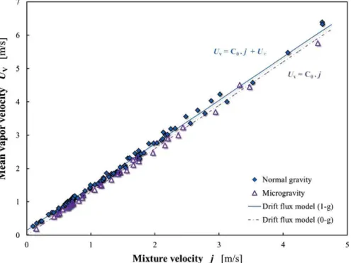
approximately equal to 1.2 for a pipe of 4-cm diameter and increases as the pipe diameter decreases. In experiments on subcooled flow boiling corresponding to bubbly and slug flows, Narcy (2014) showed that the mean vapor velocity
UV is also well predicted by the drift flux model with a value of C0 = 1.25 (Fig. 3). In vertical upward flow on
the ground, the mean vapor velocity UV = C0j + U∞, where U∞ is the bubble drift velocity. For bubbly flows,
U∞= 1.53
¡
g (ρL− ρV) σ/ρ2L
¢1/4
(Harmathy, 1960); for slug flows, U∞ = 0.35 √
gD (Wallis, 1969). Data in 1-g
upward flows are plotted in Fig. 3 and compared with the drift flux model for bubbly flows with U∞= 0.145 m/s.
The validity of the drift flux model for bubbly flow in microgravity with a C0 value larger than 1 proves that,
despite a negligible bubble drift velocity (U∞ = 0), mean gas velocity UG is larger than mixture velocity j. For
bubbly flow, the velocity difference UG– j is due to the most important concentration of bubbles in the central part
of the tube, where liquid velocity is more important (Colin et al., 1996). Local bubble drift velocity is close to zero in microgravity, as confirmed by simultaneous local measurements of gas and liquid velocities (Kamp et al., 1993;
FIG. 3: Mean vapor velocity for bubbly and slug flows in subcooled boiling in microgravity (triangles) and normal-gravity upward flow (diamonds).
Colin et al., 2012). The key problem in bubbly flow is thus the prediction of the radial void fraction distribution. An analytical model including the effects of lift force, added mass force, and turbulent dispersion was recently developed to predict the void fraction distribution in 1-g upward and downward flow and in microgravity. It clearly points to the role of interactions between bubbles and the turbulence of the liquid phase in microgravity conditions (Colin et al., 2012; Chahed et al., 2002).
Concerning annular flow, film thickness measurements have mostly been performed in gas-liquid flows without phase change. Determining film thickness in annular flow is crucial to determining wall shear stress and HTCs. Bousman (1995) measured film thickness using conductive probes and cross-correlating signals to obtain velocities. Bousman and Dukler (1994), using four sets of probes placed around the circumference of the tube, observed that the annular film is axisymmetric in microgravity. With a fifth sensor downstream, they observed large disturbances or roll waves and showed that large liquid velocities increase the averaged film thickness and that high gas-flow velocities decrease it. These authors also pointed out the effect of surface tension and liquid viscosity on film thickness and wave structures. Wang et al. (2004) analyzed the structure of liquid film using a conductive probe made of two parallel small wires traversing the pipe section. They compared the results obtained in vertical upward flow in normal gravity and that in microgravity conditions, finding that wave height and relative interfacial roughness decrease when the gas Reynolds number increases. In microgravity, the values of wave height and interfacial roughness are less than half of their values in normal gravity. Ohta (2003) also observed a reduction in wave disturbances in microgravity conditions for air-water flows and for boiling R-113 flows in comparison with 1-g and 2-g upward flow. At low quality, the frequency of passing disturbance waves increases with gravity. Ohta developed an analytical model to calculate the velocity and temperature profiles in the liquid film and found that film thickness is larger in microgravity than in 1-g and 2-g for qualities smaller than 0.8 and moderate mass fluxes.
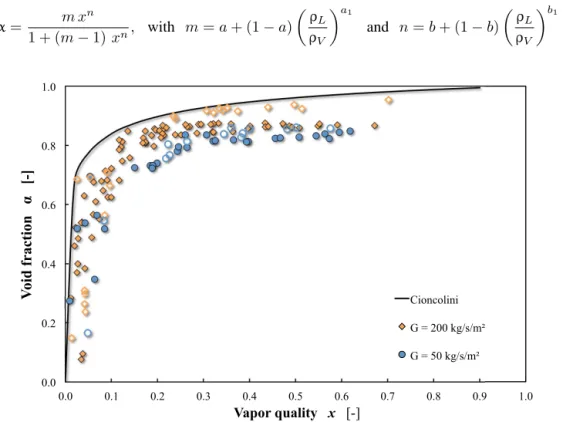
Narcy et al. (2014a) recently performed void fraction measurements in annular flow boiling of HFE-7000 in a 6-mm-diameter tube using capacitance probes (Fig. 4). Their results are compared with the correlation provided by Cioncolini and Thome (2012a) to predict the void fraction in annular flow:
α = m x n 1 + (m − 1) xn, with m = a + (1 − a) µ ρL ρV ¶a1 and n = b + (1 − b) µ ρL ρV ¶b1 (2) 0.0 0.2 0.4 0.6 0.8 1.0 0.0 0.1 0.2 0.3 0.4 0.5 0.6 0.7 0.8 0.9 1.0 V oi d fr ac ti on [-] Vapor quality x [-] Cioncolini G = 200 kg/s/m² G = 50 kg/s/m²
FIG. 4: Void fraction in saturated boiling according to vapor quality in 1-g (closed symbols) and 0-g (open symbols), compared with the model proposed by Cioncolini and Thome (2012a).
where a = –2.129, a1 = –0.2186, b = 0.3487, and b1 = 0.515. The void fraction values are plotted for two mass
fluxes, G = 50 and G = 200 kg/m2/s. Equation (2) overpredicts void fraction value in 1-g and in microgravity for
G = 50 kg/m2/s. The results show that the void fraction is significantly higher in microgravity. Film thickness δ was
deduced from the void fraction after estimating the liquid droplet entrainment e according to Cioncolini and Thome (2012b): δ = D 2 " 1 − s α µ 1 + ρV ρL 1 − x x e ¶# with e =¡1 + 279.6 We−0.8395c ¢−2.209 (3)
where Wec is the Weber number of the vapor core with entrained droplets. The film thickness evolution with quality
is plotted in Fig. 5 for normal and microgravity conditions. In microgravity, the measured film thickness values for
G = 200 kg/m2/s agree well with Eq. (3). This correlation underpredicts the film thickness for low mass flux (G =
50 kg/m2/s) in microgravity and for all mass fluxes in normal gravity. Film thickness in 1-g is much larger than that in 0-g, especially for G > 100 kg/m2/s. This result contradicts the analytical model of Ohta (2003) for the prediction of film thickness and heat transfer in annular flow. Additional experiments are needed to provide local measurements of film thickness as well as a detailed description of the film structure (interfacial waves, droplet entrainment, etc.).
4. PRESSURE DROP, WALL FRICTION, AND INTERFACIAL FRICTION
Most studies performed in microgravity conditions concern gas-liquid flow without phase change (Bousman and McQuillen, 1994; Zhao and Rezkallah, 1995; Colin et al., 1996; Zhao et al., 2001). Some results exist for liquid-vapor flow (Chen et al., 1991; Narcy et al., 2014a) but in an adiabatic test section. The wall shear stress τW can be
determined from pressure drop dP/dz and void fraction α measurements using the momentum balance of the mixture in adiabatic flow:
−dP dz −
4τW
D − (ρL(1 − α) + ρVα) g = 0 (4)
In microgravity flows without phase change, wall shear stress is directly proportional to pressure drop.
Colin et al. (1996) presented some results for air and water bubbly and slug flow in tubes of different di-ameters. In bubbly flow, the wall friction factor is well predicted by the single-phase flow correlation of Blasius
(fL= 0.079Re−1/4L ), for a Reynolds number ReL(based on liquid properties and mean liquid velocity UL) between
0.0 0.1 0.2 0.3 0.4 0.5 0.0 0.1 0.2 0.3 0.4 0.5 0.6 0.7 0.8 0.9 1.0 Li q u id fi lm th ic k n es s [m m ] Vapor quality x [-] G = 200 kg/s/m² G = 50 kg/s/m² Cioncolini - G = 200 kg/s/m² Cioncolini - G = 50 kg/s/m²
20,000 and 70,000. The Blasius correlation tends to underestimate the friction factor when ReLis smaller than 20,000
because, as the Reynolds number decreases, the thickness of the viscous layer increases and the presence of large bubbles affects this layer near the tube wall. Zhao (2010) proposed expressing the wall friction factor versus mixture velocity and liquid viscosity. The agreement with experimental data is better than with the Blasius correlation for Reynolds numbers between 6,000 and 30,000.
For slug and annular flows, the frictional pressure drop 4τW/D was compared by Zhao and Rezkallah (1995) and
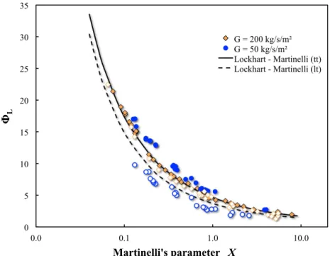
Chen et al. (1991) with different empirical models [homogeneous model (Lockhart and Martinelli, 1949; Friedel, 1979)]. Awad and Muzychka (2010) and Fang et al. (2012) proposed a modified expression of the correlation of Lockhart and Martinelli and found good agreement with the experimental data. According to Lockhart and Mar-tinelli (1949), the frictional pressure gradient in two-phase flows can be expressed versus the single-phase liquid flow frictional pressure gradient (dP/dz)Land a multiplier φ2L:
4τW D = µ dP dz ¶ L φ2L with φ2L= 1 + C X + 1 X2 and X = µ dP dz ¶ L Á µ dP dz ¶ V (5)
C = 20 if the single-phase liquid and vapor flows are both turbulent (tt), and C = 12 if the single-phase liquid flow
is laminar and the single-phase vapor flows are turbulent (lt). In Fig. 6 we plot the experimental value φL versus
Martinelli’s parameter X for G = 50 and G = 200 kg/m2/s. For G = 200 kg/m2/s, the wall shear stress is the same in normal and microgravity conditions and close to the Lockhart and Martinelli correlation for turbulent liquid and vapor flows. At G = 50 kg/m2/s, single-phase liquid flow is laminar and single-phase vapour flow is turbulent. Wall shear stress is much higher in 1-g than in 0-g for G values smaller than 100 kg/m2/s. Although these correlations give a reasonable estimation of pressure drop, they are of limited interest in the prediction of flow dynamics. To reproduce the dynamics of annular flow (film thickness and flow velocities), a two-fluid model must be used that includes one momentum balance equation for each phase (liquid and gas). In steady flow, the two momentum balance equations are functions only of pressure drop, void fraction, and wall and interfacial shear stresses. By measuring pressure drop and void fraction at the same time, it is therefore possible to calculate both wall shear stress from Eq. (4) and interfacial shear stress from the momentum balance equation for vapor in adiabatic flow:
0 5 10 15 20 25 30 35 0.0 0.1 1.0 10.0 L Martinelli's parameter X G = 200 kg/s/m² G = 50 kg/s/m² Lockhart - Martinelli (tt) Lockhart - Martinelli (lt)
FIG. 6: Experimental two-phase multiplier according to the Martinelli parameter for 1-g (closed symbols) and 0-g (open symbols), compared with two correlations proposed by Lockhart and Martinelli (1949).
−αdP dz − 4τi √ α D − ρVαg = 0 (6)
Bousman and Dukler (1993) determined interfacial shear stress and provided relationships for the interfacial friction factor fi ≈ 2τi/ρVUV2 versus void fraction. More recent studies have focused on analysis of the liquid film
struc-ture (film thickness, interfacial waves). Wang et al. (2004) related the interfacial friction factor fi to the interface
roughness, reporting that the value of fiincreases with interfacial roughness. Narcy et al. (2014a) showed that the
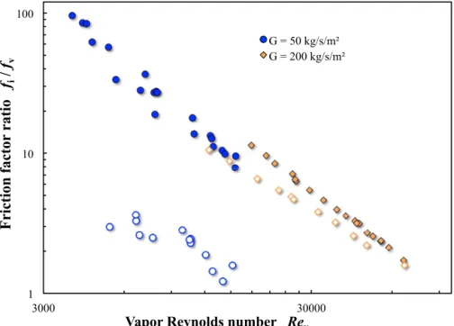
interfacial friction factor depends on both liquid film thickness δ and the Reynolds number of the vapor core flow. They plotted fi/fV versus the Reynolds number of the vapor, ReV = jVD/vV, where fV = 0.079 (ReV)−1/4and
found a smaller value of fiin microgravity for G < 400 kg/m2/s (Fig. 7). The difference between interfacial friction
factors in 1-g and 0-g greatly increases as G decreases. Ohta (2003) proposed a correlation to predict the ratio of the interfacial friction factors in 1-g and 0-g:
fi−1g fi−0g = 1 + 0.08 µ 1 − x x ¶0.9 1 Fr with Fr = j2 L gD (7)
In Fig. 8, this ratio is plotted versus quality. Equation (7) seems to reproduce the effect of gravity on interfacial shear stress. Interfacial shear stress is very difficult to measure because it requires good accuracy for both pressure drop and void fraction. Very few measurements exist in microgravity, and work has still to be done to confirm the existing results. Interfacial shear stress is strongly linked to interfacial disturbance waves at the liquid film surface. According to Ohta (2003), the celerity and frequency of the disturbance waves are larger in 1-g upward flow than in microgravity. In microgravity the liquid film becomes smoother. A more detailed analysis of the structure of liquid film in both 1-g and 0-g would be useful in developing a model of interfacial shear stress.
1 10 100 3000 30000
F
ri
cti
on
fac
tor
r
ati
o
f
i/
f
vVapor Reynolds number Rev
G = 50 kg/s/m² G = 200 kg/s/m²
FIG. 7: Dimensionless interfacial friction factor versus vapor Reynolds number in 1-g (closed symbols) and in 0-g (open symbols).
1 10 100 0.0 0.1 0.2 0.3 0.4 0.5 0.6 0.7 0.8 0.9 1.0 F ri cti on fac tor r ati o fi 1-g / fi 0-g Vapor quality x G = 200 kg/s/m² G = 100 kg/s/m² G = 50 kg/s/m² Eq. 7 - G = 200 kg/s/m² Eq. 7 - G = 100 kg/s/m² Eq. 7 - G = 50 kg/s/m²
FIG. 8: Ratio of interfacial friction factors in 1-g and 0-g.
5. HEAT TRANSFER COEFFICIENT
Little research has been carried out on flow boiling heat transfer (FBHT) in reduced gravity. The reason is that FBHT requires both large heat loads and available room in a µ-g apparatus for experiments. Few data are available and coherence in existing data is missing, perhaps because of severe restrictions in test apparatus specifications, strict prescription of experimental conditions, too few opportunities to perform additional experiments for repeatability, and short-lived µ-g conditions, among other drawbacks. Nevertheless, new results were recently obtained by Japanese, European, and American teams in parabolic flights.
Saito et al. (1994) reported heat transfer data for flow boiling of water in a horizontal annulus with a central heater rod during parabolic flight. Contrary to terrestrial conditions, where stratified flow often occurs except at high mass flux, under microgravity conditions, because of reduced buoyancy, bubbles barely detach from the heater rod. The bubbles flow along the heater rod and grow because of vaporization on the heater rod, and/or they coalesce around the heater. Under microgravity this tendency is more noticeable in lower inlet fluid velocity, higher heat flux, and lower inlet fluid subcooling. Saito et al. (1994) found differences in local HTCs to be very small, however, in spite of large differences in the flow regimes under earth gravity and microgravity.
Lui et al. (1994) carried out heat transfer experiments in subcooled flow boiling of R-113 using a tubular test section (12-mm internal diameter, 914.4-mm length). They found subcooled boiling heat transfer to be enhanced in microgravity conditions, reporting HTCs approximately 5–20% higher in microgravity and generally increasing with higher qualities. According to the authors, the greater movement of vapor bubbles on the heater surface causes more localized turbulence, believed to be responsible for increased HTCs.
Ohta (2003) studied flow boiling of R-113 in a vertical transparent tube (8-mm internal diameter, 100-mm length) internally coated with a gold film in parabolic flight. He found mass flux ranging 150–600 kg/m2/s and heat flux rang-ing 0.25–12 W/cm2. Ohta examined bubbly, slug, and annular flow regimes and, as usual, observed large variations in bubble and slug sizes with gravity level at low mass fluxes. He reported that the HTC was barely affected by the various gravity levels provided that the heat transfer was controlled by nucleate boiling (NB). He also observed that in the two-phase forced-convection heat transfer regime (TFC), where nucleate boiling was completely suppressed (con-vective boiling), the HTC varied significantly with gravity levels, resulting in lower values in microgravity compared with those in normal gravity.
Celata and Zummo (2009) performed flow-boiling experiments in parabolic flight at low gravity with FC-72 using transparent test sections (Pyrex tubes with three diameters: 2.0 mm, 4.0 mm, and 6.0 mm), and collected a significant data set of HTCs in flow boiling and flow patterns at low and normal gravity. According to the investigators, low and normal gravity lead to a larger bubble size accompanied by deterioration in the heat transfer rate. The influence of gravity level on heat transfer tends to decrease as the fluid velocity increases, also depending on vapor quality. For low quality, the influence of gravity is negligible when fluid velocity is greater than 25 cm/s. For quality higher than 30%, no gravity level influence is observed independent of fluid velocity.
Baltis et al. (2012) reported the results of a quantitative analysis of the change in HTC in subcooled FC-72 flow boiling at different gravity conditions. They analyzed data for three tube diameters (2.0, 4.0, and 6.0 mm) and reported that the HTC decreases up to 30–40% in microgravity in comparison with terrestrial gravity. The influence of mass flux and heat flux was described. When either mass flux or heat flux is increased, the influence of gravity seems to diminish. Mass flux increases lead to an increase in inertial forces, which reduce the influence of surface forces acting on bubbles and in turn reduces the influence of gravity. Increased heat flux causes the subcooled boiling flow to become more and more saturated. In saturated flow boiling, gravity shows a small influence on heat transfer.
A new technique for the measurement of heat transfer distributions was developed by Kim et al. (2012), who used an infrared camera to determine the temperature distribution in a multilayer consisting of a silicon substrate coated with a thin insulator. Based on a recent parabolic flight campaign, Narcy (2014) pointed out that in the nucleated boiling regime at low quality, the HTC is smaller in microgravity.
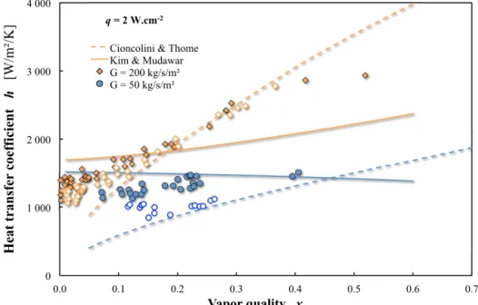
Narcy (2014) reported heat transfer measurements in flow boiling for mass flux G = 50–400 kg/m2/s and wall heat fluxes q equal to 1, 2, and 4 W/cm2. Figure 9 plots HTC versus quality for two mass fluxes and a wall heat flux q = 2W/cm2. At G = 200 kg/m2/s, the HTCs are similar in 1-g and in 0-g except at low qualities (x < 0.15) in the subcooled boiling regime corresponding to bubbly and slug flow. At higher qualities, they do not depend on gravity and increase with quality. An annular flow regime is observed; the bubble nucleation in the liquid film disappears, and heat transfer is due to evaporation of the liquid film. At a lower mass flux G = 50 kg/m2/s, HTC is always lower in 0-g than in 1-g, even for quality higher than 0.15 corresponding to annular flow. The evolution of HTC with quality is smaller than for higher mass flux. This evolution is characteristic of the persistence of a nucleate boiling regime also in annular flow. The experimental results were compared to two correlations. Kim
0 1 000 2 000 3 000 4 000 0.0 0.1 0.2 0.3 0.4 0.5 0.6 0.7 H eat tr an sfe r c oe ffi ci en t h [W /m ²/ K ] Vapor quality x Cioncolini & Thome
Kim & Mudawar G = 200 kg/s/m² G = 50 kg/s/m²
q = 2 W.cm-2
FIG. 9: Experimental HTCs as a function of quality for q = 2W/cm2in 1-g (closed symbols) and 0-g (open symbols), compared with the correlations of Kim and Mudawar (2013) and Cioncolini and Thome (2011).
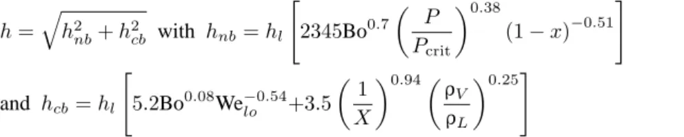
and Mudawar (2013) took into account the contribution of nucleate and convective boiling in their evaluation of the HTC: h = q h2 nb+ h2cb with hnb= hl " 2345Bo0.7 µ P Pcrit ¶0.38 (1 − x)−0.51 # and hcb= hl " 5.2Bo0.08We−0.54 lo +3.5 µ 1 X ¶0.94µ ρV ρL ¶0.25# (8)
where Bo is a boiling number, Bo= q/GhLV; hl is the single-phase flow HTC calculated with the Dittus-Boelter
correlation using superficial liquid velocity; and Welois a Weber number for single-phase liquid flow. This
corre-lation is in good agreement with experimental data at low mass flux in normal gravity, where both nucleate boil-ing and convective boilboil-ing play a significant role. Equation (8) seems to overestimate HTC at low quality prob-ably because the very smooth surface of the sapphire tube limits the nucleate boiling contribution in this experi-ment. For high quality and high mass flux, dominated by two-phase forced convection, Eq. (8) underestimates HTC.
The experimental results are also compared to the model of Cioncolini and Thome (2011) predicting the HTC for an evaporating turbulent liquid film:
h = λL δ 0.0776 µ δu∗ νL ¶0.9 Pr0.52L with u∗= r τW ρL (9)
where PrLis the Prandtl number of the liquid. In an annular flow regime at high mass flux G > 100 kg/m2/s, nucleation
in the liquid film almost disappears, which can be explained by the smooth surface of the sapphire tube and the relative low heat fluxes (q < 4 W/cm2). Then the heat transfer is dominated by two-phase forced convection. It increases with mass flux and quality and is almost independent of wall heat flux for values smaller than 4 W/cm2. In Fig. 10, HTCs are compared with the those predicted by Cioncolini and Thome (2011) for both normal and microgravity
! " ! # ! $ ! % ! & ! ! " ! # ! $ ! % ! & ! ' ! ! " # $% &" # '( ) * ' ' +, -. / -0 1 2"345!"#'()*' ''+,-./-01' ()# *+,-#,.! ()% !*+,-#,.! /01234567! 8!9"&:!
FIG. 10: Comparison of the predicted HTC value from the Cioncolini and Thome model (2011) and the experimental values in 1-g (closed symbols) and 0-g (open symbols).
conditions. The good agreement between the experiments and the model confirms the dominant role of two-phase forced convection in heat transfer on these experimental flow parameter ranges.
Ohta and Baba (2013) reported new measurements taken at low mass flux, G = 40 and 60 kg/m2/s for heat flux up to 1.8 W/cm2. At such low values, nucleate boiling remains in annular flow (NBA regime). The HTC is independent of quality up to the critical heat flux, increases with wall heat flux, and is independent of mass flux and gravity level. Ohta and Baba provide a useful summary table of the observed heat transfer mode versus mass flux, quality, and heat flux as well as the possible effect of gravity.
Based on the findings of Ohta (2003), Celata and Zummo (2009), Baltis et al. (2012), and Narcy et al. (2014a), Ohta and Baba’s (2013) summary table of heat transfer modes is redrawn in Fig. 11. At low quality values in the subcooled boiling regime, nucleate boiling is observed in bubbly and slug flows for very low to high mass fluxes. According to Baltis et al. (2012) and Narcy et al. (2014a), this regime is sensitive to gravity. For high mass fluxes, the effect of gravity disappears. At high quality, in all of the aforementioned studies, heat transfer is not affected by gravity except at very low mass fluxes. For moderate quality and low mass flux, Ohta (2003) and Narcy et al. (2014a) found significant heat transfer decreases in microgravity. At very low mass fluxes, they observed nucleate boiling in the annular flow regime at moderate and high qualities. In these regimes, a decrease in HTC in microgravity was observed. In Fig. 11, the color areas show the regimes where gravity affects HTC. On the basis of Fig. 11, future experiments in microgravity should focus on low mass fluxes to confirm the first observed trends. This is the objective of future flow boiling experiments aboard the International Space Station in the Japanese KIBO experiment module. Experiments will be performed in a 4-mm-diameter copper or glass tube with internal gold coating, using FC-72 (Baba et al., 2011).
6. CONCLUSION
Two-phase flows under microgravity have been studied primarily in air-water mixtures, and many data on flow pattern, pressure drop, and void fraction exist. Research on flow boiling in microgravity is more recent, and the data reported mainly concern flow pattern and heat transfer. In adiabatic and boiling flows, the same flow patterns are observed in vertical 1-g upward flow and in microgravity conditions: bubbly flow, slug/transition flow, and annular flow. The transition between bubbly and slug flow is reached for a higher void fraction in flow boiling than for adiabatic flows because of shorter test sections and smaller bubbles nucleated on the wall. Because wall friction and wall heat transfer are very sensitive to flow pattern, particular attention has been paid to determining flow pattern transitions.
22
Low x
(<0.1)
subcooled
boiling
Moderate x
(0.1->0.3)
High x
(>0.3)
annular
flow
High G (>200 kg/m
2/s)
NB
TFC
TFC
Low G
(100 ->200
kg/m2/s)
High q (>2W/cm2)
NB
NBA
NBA
Low q (<2W/cm2)
NB
TFC
TFC
Very low G (<80 kg/m
2/s)
NB
NBA
NBA
FIG. 11: Summary table for the HTC (modified from Ohta and Baba, 2013). NB: nucleate boiling, NBA: nucleate boiling in annular flow, TFC: Two-phase forced convection.
The results of recent experiments by Narcy et al. (2014b) on flow boiling in a tube under normal and microgravity conditions were described and compared with other experiments and models or correlations from the literature. In bubbly and slug flow, gas velocity is well predicted by the drift flux model. These flow patterns correspond to subcooled boiling regimes dominated by nucleate boiling. Wall heat transfer increases with wall heat flux and is much smaller in microgravity than in 1-g upward flow. In the annular flow regime in saturated boiling, bubble nucleation at the wall disappears except at very low mass flux (G < 80 kg/m2/s). In this regime, liquid film thickness, determined from void fraction measurements, is significantly larger in 1-g than in 0-g. Wall shear stress is well predicted by the classical correlations of Lockhart and Martinelli.
Thanks to simultaneous measurements of pressure drop and void fraction, original data on interfacial shear stress have been obtained. Interfacial shear stress is much lower in 0-g than in 1-g, especially at low mass fluxes. In annular flow, when bubble nucleation disappears, heat transfer is controlled by forced convection through the evaporating liquid film, and HTC is well predicted by the Cioncolini and Thome (2011) model.
Experiments for very low mass fluxes (G < 80 kg/m2/s) were carried out by Ohta and Baba (2013) and Narcy (2014). The results need to be confirmed by future experiments, some of which will be conducted in the Japanese experiment module KIBO aboard the International Space Station. These experiments will gather data at very low mass flux without g-jitter perturbation as in parabolic flight experiments and at the long duration required to reach thermal equilibrium, especially with metal tubes.
ACKNOWLEDGMENTS
The authors thank the Centre National d’Etudes Spatiales, the Research Foundation for Aeronautics and Space, and the European Space Agency for their financial support of this study, the PhD thesis, and postdoctoral grants, and Novespace for the organization of the parabolic flight campaigns.
REFERENCES
Awad, M. M. and Muzychka, Y. S., Review and modelling of two-phase frictional pressure gradient at microgravity conditions, Proc. of the ASME Fluid Engineering Division Summer Meeting, Montreal, Aug. 1-5, 2010.
Baba, S., Sakai, T., Sawada, K., Kubota, C., Wada, Y., Shinmoto, Y., Ohta, H., Asano, H., Kawanami, O., Suzuki, K., Imai, R., Kawasaki, H., Fujii, K., Takayanagi, M., and Yoda, S., Proposal of experimental setup on boiling two-phase flow on-orbit experiments onboard Japanese experiment module ”KIBO,” J. Phys. Conf. Ser., vol. 327, p. 012055, 2011.
Baltis, C., Celata, G. P., Cumo, M., Saraceno, L., and Zummo, G., Gravity influence on heat transfer rate in flow boiling, Micro-gravity Sci. Technol., vol. 24, pp. 203–213, 2012.
Bousman, S., Studies of two-phase gas-liquid flow in microgravity, National Aeronautics and Space Administration, Report No. 195434, 1995.
Bousman, S. and Dukler, A. E., Studies of gas-liquid flow in microgravity: Void fraction, pressure drop and flow pattern, Proc. of the 8th Annual Microgravity Science and Space Processing Symposium, Reno, NV, 1994.
Bousman, S., McQuillen, J., and Witte, L., Gas-liquid flow pattern in microgravity: Effects of tube diameter, liquid viscosity and surface tension, Int. J. Multiphase Flow, vol. 22, pp. 1035–1053, 1996.
Bousman, W. S. and Dukler, A. E., Study of gas-liquid flow in microgravity: Void fraction, pressure drop and flow pattern, Proc. of the 1993 ASME Winter Meeting, New Orleans, LA, 1993.
Bousman, W. S. and McQuillen, J. R., Characterisation of annular two-phase gas-liquid flows in microgravity, Proc. of the 2nd NASA Microgravity Fluid Physics Conference, Cleveland, June 21-23, 1994.
Celata, G. P. and Zummo, G., Flow boiling heat transfer in microgravity: Recent progress, Multiphase Sci. Technol., vol. 21, no. 3, pp. 187–212, 2009.
Chen, I. Y., Downing, R. S., Keshock, E., and Al-Sharif, M., Measurements and correlation of two-phase pressure drop under microgravity conditions, J. Thermophys., vol. 5, pp. 514–523, 1991.
Chahed, J., Colin, C., and Masbernat, L., Turbulence and phase distribution in bubbly pipe flow under micro-gravity condition, J. Fluid Eng., vol. 124, pp. 951–956, 2002.
Cioncolini, A. and Thome, J. R., Algebraic turbulence modeling in adiabatic and evaporation annular two-phase flow, Int. J. Heat Fluid Flow, vol. 32, pp. 805–817, 2011.
Cioncolini, A. and Thome, J. R., Void fraction prediction in annular two-phase flow, Int. J. Multiphase Flow, vol. 43, pp. 72–84, 2012a.
Cioncolini, A. and Thome, J. R., Entrained liquid fraction prediction in adiabatic and evaporation annular two-phase flow, Nucl. Eng. Des., vol. 32, pp. 200–213, 2012b.
Colin, C. and Fabre, J., Gas-liquid pipe flow under microgravity conditions: Influence of tube diameter on flow patterns and pressure drops, Adv. Space Res., vol. 16, no. 7, pp. 137–142, 1995.
Colin, C., Fabre, J., and Dukler, A. E., Gas-liquid flow at microgravity conditions—I: Dispersed bubble and slug flow, Int. J. Multiphase Flow, vol. 17, pp. 533–544, 1991.
Colin, C., Fabre, J., and Kamp, A., Turbulent bubbly flow in a pipe under gravity and microgravity conditions, J. Fluid Mech., vol. 711, pp. 469–515, 2012.
Colin, C., Fabre, J., and McQuillen, J., Bubble and slug flow at microgravity conditions: State of knowledge and open questions, Chem. Eng. Com., vol. 141-142, pp. 155–173, 1996.
Colin, C., Riou, X., and Fabre, J., Bubble coalescence in gas-liquid flow at microgravity conditions, Microgravity Sci. Technol., vol. 20, pp. 243–246, 2008.
Dukler, A. E., Fabre, J. A., McQuillen, J. B., and Vernon, R., Gas-liquid flow at microgravity conditions: Flow patterns and their transitions, Int. J. Multiphase Flow, vol. 14, pp. 389–400, 1988.
Elkow, K. J. and Rezkallah, K. S., Void fraction measurements in gas-liquid flows under 1-g and 0-g conditions using capacitance sensors, Int. J. Multiphase Flow, vol. 23, no. 5, pp. 815–829, 1997.
Fang, X., Zhang, H., Xu, Y., and Su, X., Evaluation of using two-phase frictional pressure drop correlations for normal gravity to microgravity and reduced gravity, Adv. Space Res., vol. 49, pp. 351–364, 2012.
Friedel, L., Improved friction pressure drop correlations for horizontal and vertical two-phase pipe flows, 3R International, vol. 7, pp. 485–491, 1979.
Harmathy, T., Velocity of large drops and bubbles in media of infinite and restrictive extent, AIChE J., vol. 1, pp. 289–295, 1960. Hazuku, H., Takamasa, T., and Hibiki, T., Characteristics of developing vertical bubbly flow under normal and microgravity
conditions, Int. J. Multiphase Flow, vol. 38, pp. 53–66, 2012.
Huckerby, S. C. and Rezkallah, S. K., Flow pattern observations in two-phase gas liquid flow in a straight tube under normal and microgravity conditions, Proc. of the National Heat Transfer Conference, San Diego, CA, Jul., 1992.
Jayawardena, S. S., Balakotaiah, V., and Witte, L. C., Flow pattern transition maps for microgravity two-phase flows, AIChE J., vol. 43, pp. 1637–1640, 1997.
Kamp, A., Chesters, A. K., Colin, C., and Fabre, J., Bubble coalescence in turbulent flows: A mechanistic model for turbulence induced coalescence applied to bubbly pipe flows under microgravity conditions, Int. J. Multiphase Flow, vol. 27, pp. 1363– 1396, 2001.
Kamp, A., Colin, C., and Fabre, J., Bubbly flow in pipe: influence of gravity upon void and velocity distributions, Proc. of the 3rd World Conference on Experimental Heat Transfer, Fluid Mechanics and Thermodynamics, Honolulu, Oct 30 – Nov 6, 1993. Kim, T. H., Kommer, E., Dessiatoun, S., and Kim, J., Measurement of two-phase flow and heat transfer parameters using infrared
thermometry, Int. J. Multiphase Flow, vol. 40, pp. 56–67, 2012.
Kim, S. and Mudawar, I., Universal approach to predict saturated boiling heat transfer in mini/micro-channels — part II — Two-phase heat transfer coefficient, Int. J. Heat Mass Transfer, vol. 64, pp. 1239–1256, 2013.
Lockhart, R. and Martinelli, R., Proposed correlation of data for isothermal two-phase two-component flow in pipes, Chemical Eng. Progress, vol. 45, no. 1, pp. 39–48, 1949.
Lui, R. K., Kawaji, M., and Ogushi, T., An experimental investigation of subcooled flow boiling heat transfer under microgravity conditions. Heat transfer, Proc.of the 10th International Heat Transfer Conference, Brighton, UK, Boca Raton, FL: CRC Press, pp. 497–502, 1994.
McQuillen, J., Colin, C., and Fabre, J., Ground-based gas-liquid flow research in microgravity conditions: State of knowledge, Space Forum, Edt. Overseas Publishers Association N.V., vol. 3, pp. 165–203, 1998.
University of Toulouse, 2014.
Narcy, M., De Malmazet, E., and Colin, C., Flow boiling in tube under normal gravity and microgravity conditions, Int. J. Multi-phase Flow, vol. 60, pp. 50–63, 2014a.
Narcy, M., Scammel, A., Kim, J., and Colin, C., Flow boiling under microgravity conditions: Comparative study of two experi-mental data sets, IHTC15-9072, Proc. of the 15th International Heat Transfer Conference, Kyoto, Japan, Aug 10-15, 2014b. Ohta, H., Experiments on microgravity boiling heat transfer by using transparent heaters, Nucl. Eng. Des., vol. 175, pp. 167–180,
1997.
Ohta, H., Microgravity heat transfer in flow boiling, Adv. Heat Transfer, vol. 37, pp. 1–76, 2003.
Ohta, H. and Baba, S., Boiling experiments under microgravity conditions, Exp. Heat Transfer, vol. 26, no. 2-3, pp. 266–295, 2013. Reinarts, T. R., Adiabatic two phase flow regime data and modeling for zero and reduced (horizontal flow) acceleration fields
[dissertation], College Station, TX: Texas A&M University, 1993.
Saito, M., Yamaoka, N., Miyazaki, K., Kinoshita, M., and Abe, Y., Boiling two-phase flow under microgravity, Nucl. Eng. Des., vol. 146, pp. 451–461, 1994.
Takamasa, T., Iguchi, T., Hazuku, T., Hibiki, T., and Ishii, M., Interfacial area transport of bubbly flow under microgravity envi-ronment, Int. J. Multiphase Flow, vol. 29, pp. 291–303, 2003.
Wallis, G., One Dimensional Two-Phase Flow, New York: McGraw-Hill, 1969.
Wang, Z., Gabriel, K. S., and Manz, D. L., The influence of wave height on the interfacial friction in annular gas-liquid flow under normal and microgravity conditions, Int. J. Multiphase Flow, vol. 30, pp. 1193–1211, 2004.
Zhao, J. F., Influence of bubble initial size on bubble-to-slug transition, J. Eng. Thermophys., vol. 26, pp. 793–795, 2005. Zhao, J. F., Two-phase flow and pool boiling heat transfer in microgravity, Int. J. Multiphase Flow, vol. 36, pp. 135–143, 2010. Zhao, J. F. and Hu, W. R., Slug to annular flow transition of microgravity two-phase flow, Int. J. Multiphase Flow, vol. 26, pp.
1295–1304, 2000.
Zhao, J. F., Xie, J. C., Lin, H., Hu, W. R., Ivanov, A. V., and Belyaev, A. Y., Experimental studies on two-phase flow patterns aboard the Mir space station, Int. J. Multiphase Flow, vol. 27, pp. 1931–1944, 2001.
Zhao, L. and Rezkallah, K. S., Gas liquid flow patterns at microgravity conditions, Int. J. Multiphase Flow, vol. 19, pp. 751–763, 1993.
Zhao, L. and Rezkallah, K. S., Pressure drop in gas-liquid flow patterns at microgravity conditions, Int. J. Multiphase Flow, vol. 21, pp. 837–849, 1995.
Zuber, N. and Findlay, J. A., Average volumetric concentration in two-phase systems, J. Heat Transfer, vol. 87, no. 4, pp. 453–468, 1965.