HAL Id: hal-01178266
https://hal.archives-ouvertes.fr/hal-01178266
Submitted on 17 Jul 2015
HAL is a multi-disciplinary open access archive for the deposit and dissemination of sci-entific research documents, whether they are pub-lished or not. The documents may come from teaching and research institutions in France or abroad, or from public or private research centers.
L’archive ouverte pluridisciplinaire HAL, est destinée au dépôt et à la diffusion de documents scientifiques de niveau recherche, publiés ou non, émanant des établissements d’enseignement et de recherche français ou étrangers, des laboratoires publics ou privés.
An Electrostatic-Discharge-Protection Solution for
Silicon-Carbide MESFET
Tanguy Phulpin, David Trémouilles, Karine Isoird, Dominique Tournier,
Philippe Godignon, Patrick Austin
To cite this version:
Tanguy Phulpin, David Trémouilles, Karine Isoird, Dominique Tournier, Philippe Godignon, et al.. An Electrostatic-Discharge-Protection Solution for Silicon-Carbide MESFET. EOS/ESD Symposium, Sep 2015, Reno, United States. �hal-01178266�
An Electrostatic-Discharge-Protection Solution for
Silicon-Carbide MESFET
T. Phulpin(1,2), D. Trémouilles(1,2), K. Isoird(1,2), D Tournier(3), P. Godignon(4),
P. Austin(1,2)
(1) CNRS, LAAS, 7 avenue du colonel Roche, F-31400 Toulouse, France (2) Univ. de Toulouse, UPS, LAAS, F-31400 Toulouse, France
Tél: +0033561336447, e-mail: [email protected]
(3 )Université de Lyon, CNRS, Laboratoire AMPERE, UMR 5005, INSA de Lyon, F-69621 Villeurbanne, France (4) Institut de Microelectrónica de Barcelona-Centre Nacional de Microelectrónica (IMB-CNM), Consejo Superior de
Investigaciones Científicas (CSIC), Universitat Autònoma de Barcelona, 08193, Spain
This work is co-copyrighted by EOS ESD Association and licensed under the Creative Commons Attribution 4.0 International License. To view a copy of this license, visit http://creativecommons.org/licenses/by/4.0/ or send a letter to Creative Commons, PO Box 1866,
Mountain View, CA 94042, USA.
50 Words Abstract – Among wide band gap material for power electronic, Silicon Carbide (SiC) is the most advanced and starts to gain market shares. We have studied planar SiC MESFET ESD robustness. To solve the problem of their low intrinsic ESD robustness, we demonstrate in this work an effective protection solution and possible improvements.
I. Introduction
Silicon carbide (SiC) devices are intended for high voltage, high frequency and high temperature applications thanks to their superior performances compared to silicon devices. The introduction of SiC into high voltage segments, such as wind and high-voltage direct current grids is also inevitable even if the big boost for these new markets should arrive with the implementation of SiC devices in electric cars’ traction systems. Recognize deficiencies and reliability studies are an approach to product qualification.
Electrostatic discharge (ESD) is considered as one of the most important factors of failures. ESD reliability should be certified during the device development.
SiC planar Metal Semiconductor Field Effect Transistor (MESFET) have been designed [1], at Ampère laboratory and manufactured at CNM laboratory in Barcelona (Spain) within the framework of the WideLab [2]. The SiC planar MESFET is designed as a component for a future integrated driver on the same crystal than a SiC power JFET. In this work, the ESD robustness of this SiC planar MESFET is studied. A slightly
improved manufacturing process is used compared to the SiC mesa MESFET already studied in [3], where ESD robustness was analyzed. The presence of a parasitic NPN transistor, which limits the ESD robustness, was demonstrated in this previous work.
In this work three different structure of SiC planar MESFET has been studied regarding ESD robustness: one reference device (MR) and two devices with internal protections: one with a Schottky on drain (MSD), preventing from drain polarity inversion and one with a Zener on drain (MZD), limiting possible drain overvoltage. Transmission line pulse (TLP) and Human Body Model (HBM) test has been carried out and results are compared in order to assess the physical behavior in the SiC device, and in order to propose new improvements for the ESD robustness.
II. Presentation of the devices
In order to facilitate their future integration on the SiC die [4], the mesa isolation of the previous study was changed by planar isolation with a P+ ring (Figure 1). Sizes and inter-electrodes distances are also different. The new structures are smaller but they allow the integration of several devices in
parallel. Therefore the nominal current will depends on the number of devices placed in parallel [5].
Figure 1: Schematic of cross section of Reference MESFET (MR)
Figure 2: Layout of MESFET with integrated protections
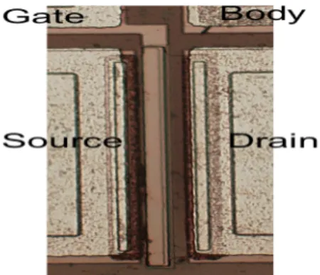
Figure 3: Photography of Reference MESFET (MR)
The layout of the three-studied MESFET is drawn on Figure 2. In grey we have the Schottky metal (Nickel), in red the P+ ring isolation, linked to the Body electrode, and in blue the metal over the N+ area that is the ohmic contact of the source and drain electrodes. They are represented on the photography on Figure 3. The P isolation is not
visible, as it is only constituted of P+ diffusion without metallization.
The Zener in the Zener on drain MESFET (MZD) device is realized by a 2 µm superposition of the N+ and P+ layers on the drain side. This diode, polarized in reverse, avoids overvoltage in between the drain and the juxtaposed substrate. For the schottky on drain MESFET (MSD), there is no N+ area below the drain electrode. Nickel metal is directly in contact with the SiC in order to obtain a Schottky junction (like the gate electrode). It avoids any negative discharge on the device.
The standard electrical characteristics of the three MESFET are almost identical, with a drain current saturation at around 15 mA for Vgs=0 V (Figure 4). The protections do not affect the electrical characteristics in static. Only the MESFET with Schottky on drain has a slight shift of 0,7V at the beginning of his characteristic due to the Schottky diode in series (Figure 5), which might be prejudicially for performances depending of the use case. The one with a Zener should have no impact on the characteristics due to his design protecting only to the body layer during ESD. The device is normally on i.e. its gate threshold voltage is negative. The voltage pinch off (Vth) is -16V and its normalized current density is equal to Jds=60 mA/mm2.
Figure 4: Static measurement at room temperature for SiC MESFET MR, with body and source electrodes grounded.
Same current level is obtained for the protected MZD MESFET.
Figure 5: Difference between Schottky on Drain and Reference MESFET: a slight shift is observed.
III. ESD robustness
measurements
To evaluate ESD robustness we have used a Transmission Line Pulse (TLP) tester and a
Human Body Model (HBM) tester.All
measurements are done at room temperature. In TLP, a 100ns voltage pulse is applied on the drain electrode whereas for the HBM it corresponds to a 100pF capacitor discharge. The main difference is in the power transmit to the device. In any case, Gate and Body electrodes are left floating and the Source electrode is grounded (More complex biasing is not done yet as they require going further with the setup and would require more material, time and caution. The voltage level applied on the drain is increased step by step until a defect is visually noticed or until a shift is detected in the reference (DC leakage) measurement verified after each step or a noticeable change is observed in the temporal waveforms, as we will shown later. It has to be noticed that in these experiments, as we are working with a normally on device, only relatively limited variations can be observed with the DC leakage measurement.
A. Reference and Schottky on drain
MESFET
Results of the TLP and HBM show that the MR and the MSD protected devices fail in a similar way (Figure 6). Indeed, during TLP measurement a failure is observed for a drain voltage range between 160 and 260V. As soon as the “DC
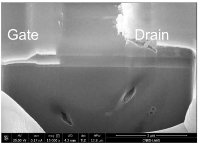
leakage” current increases, the test is stopped and devices are analyzed. Despite the failure voltage level is quite spread, all damages are always observed at the same location. Indeed a hole appears at the corner of the drain metallization, near the P+ ring (Figure 7). These MESFETs cannot drive any ESD overcurrent without being damaged (Figure 6).
We observe exactly the same behavior with the HBM test even if voltages before damages are higher due to the specific HBM resistance of 1500Ω. At around 400 V HBM, the current drastically increases for both MESFETs (Figure 8)
Figure 6: Id-Vd TLP results; Mzd can conduct some current until 1A whereas reference and Msd are suddenly damaged;
stars represents the failure occurrence.
Figure 7: SEM photography after Focus Ion Beam analysis located at the failure of a MSD after a TLP test at 160V. Cross-section 1 and 2 are respectively presented schematically
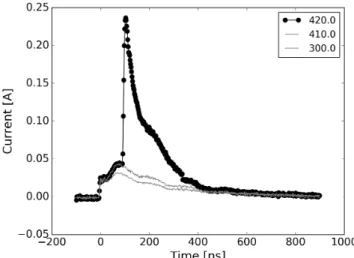
Figure 8: Current measurements during HBM tests on MR device (Source electrode grounded, drain stressed, gate and
body electrode floating); Device stressed from 20 V HBM voltage by 10 V increment (not all curve show on the figure).
A sharp current increase is observed during 420 V HBM measurement about 100ns after the pulse start, indicating
something might have be broken in the device.
The ESD robustness of these devices (MR&MSD) is very low as no ESD current can be conducted without inducing physical degradation. The Schottky on drain protection of the MESFET is not effective for ESD protection but does not reduce the ESD robustness either.
B. Zener on drain
As explained in introduction, one Zener diode has been added at the drain side. Its goal is to drive the current overflow during an ESD stress. The overcurrent will be evacuated through the body. The Zener diode is able to drive some current in reverse without being damaged. This diode can be useful for ESD protection where transient overstress occurs. We have measured this standalone Zener diode that starts to conduct current at 30 V with high internal resistance of around 10 kΩ (Figure 9). The triggering voltage is rather low, around 30 V, which is the Zener voltage for SiC [6]. However this relatively low level is not an issue for the targeted application that is the gate driver circuit for the power device.
Figure 9: Zener diode electrical characteristic between body and drain electrodes; gate and source are floating; At 30V the
diode starts to conducts current in reverse.
TCAD Sentaurus simulation confirms the different behaviors during a TLP stress (Figure 10). MR and MSD can sustain a higher drain voltage and are superposing in their representation whereas MZD has a current increase at around 30V. Due to his internal resistance, electron current increases slower than the predicted Zener current. We expect that the Zener diode is conducting current for this MESFET. Internal resistance of the body has to be adjusted to approximate the ideal behavior of the MESFET (Ron).
Figure 10: TCAD Sentaurus simulation of TLP test on three different SiC MESFET; MZD is driving current earlier than
the others, which are superposed.
Experimental TLP results (Figure 6) confirm that the robustness of the Zener protected device is better than the MR or the MSD ones. The TLP current capability is almost 1 A before destruction. However, a difference is noticed regarding the avalanche voltage. This shift can be attributed to the lateral diffusion, the gate polarization and the body resistance, not perfectly model in our
simulations, as body resistance is essentially tridimensional.
This experiment result is reproducible. Indeed, three MZD were tested and stopped before 1 A and no changes were observed on their electrical characteristics.
The Zener protection is an effective ESD solution. Nevertheless a failure at the corner appears for a TLP current level higher than 0.9A, which corresponds, to the HBM test where a failure appeared for 1250 V and 0.91 A.
The failure mechanism of the MZD appears to be different from the MR and MSD devices. Defect appears in simultaneity at both corner, and is located below the metallization where the metal was melted for the MR and MSD devices.
The Focus Ion Beam (FIB) cross-section shows holes going from the drain metal to the source side of the device, through the substrate (Figure 11). It has been correlated with TCAD Sentaurus simulation where we can observe current going from the source to the drain electrode after the Zener is triggered on. It corresponds to the classical failure of the parasitic NPN transistor. Electron current (Figure 12) coupled with intrinsic temperature gives us an idea of the localization, which correlates with the experiment.
Figure 11: SEM photography of a FIB cross section on a failure located at the corner of MZD drain electrode, after
TLP test.
Figure 12: Simulation of total current censity for MZDdevice before and after internal Zener triggering; A parasitic NPN
transistor is carrying most of the current in the structure
IV. Discussion
For one mesa-MESFET studied in the previous work [3] the impact ionization generates hole current, going in the P channel through its internal resistance, which first turns on the source-bulk PN junction due to the voltage drop, and then triggers the parasitic NPN. The electron current is increased until temperature becomes too high and creates damage at the cylindrical corner of the structure, with a failure in the SiC.
For the MR and MSD MESFET, the damages occur at the corner of the drain metallization (Figure 7). It indicates that another failure
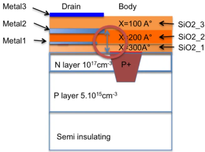
mechanism is at stake compared to the previously studied MESFET. Here, as observed in sectionIII.A, the defect localization is near the PN junction, at the end of the drain metallization, in between drain and gate electrodes (Figure 13). The highest electric field is then located in between the P+ and the drain metallization across the dielectric insulators (Figure 14). With breakdown strength between of 3 to 5 MV/cm for inter-metal SiO2 dielectric and with our layer thickness of 0.5um, this oxide breakdown voltage is around 150-250 V. As the damage appears as soon as the TLP current increases, we can conclude that there was no triggering of the parasitic NPN and that the drain voltage applied was high enough to break the insulating layer and indeed a hole is observed in the oxide and the metal is melted.
Figure 13: Schematic cross section along ”Cross1” on Figure
7..Defect is located in between the metal2 of the Drain and the
semiconductor.
Figure 14: Schematic cross section along “Cross2” on Figure 7.. Defect is actually located in between the metal2 of
the Drain and the Body P+ diffusion.
Figure 15: Several layers on the layout of SiC MR with model of several parasitic NPN taken his base in the P layer
For the MZD, drain current increase at around 115V in TLP experiment, whereas it starts before with HBM test and at 30 V with TCAD simulation. Probably due to the high body
resistance, the TLP tester is not able to detect small current variation as soon as current increase. Indeed, current starts to increase and is regulated by the Zener diode. Carriers’ density increases in the whole body region. When enough electron are present close to the source electrode, the collector of the NPN parasitic transistor will start to collect them, with the source as emitter, the P layer as basis and the drain as collector (Figure 12). The current density will increase until failure.
The simulation results suggest that the parasitic NPN, with the p-doping profile of 5.1015cm-3 in the base, is conducting the main current. This parasitic transistor is present all along the electrode length but the electrical-potential repartition in the P+ ring tends to concentrate the current at the device corners. Thanks to the distributed body resistance, the current will be spread for higher electrical potential but still will be the highest at the corners. It explains why the full length of the bipolar transistor is not used before the MESFET is destroyed (Figure 15).
V. Outlook for improvements
As discussed, to increase the failure level for MZD device, one can optimize the body P+-ring resistance. A better homogeneity of the electrical potential in the ring along the source should help to optimize the robustness and avoid an electrical concentration of the current in the corners, which accelerate the destruction of the device. If a metal contact was added over the P+, the electric field will be homogenized along the whole P+ finger. Increasing the distance between the P+ and the drain metallization layer will also allow a higher robustness. Indeed the electric field in the oxide will be reduced and the oxide breakdown pushed to higher voltages. This improvement is also difficult to simulate, because different effects have to be taken into account like the electric field of the lateral body, the oxide and metal layers. Furthermore, technology wise on could also increase the thickness of the oxide layer in order to increase his breakdown voltage.
VI. Conclusion
Different ESD protection structures for SiC planar MESFET have been compared in this work. We
have experimentally validated the efficiency of internal protection against ESD for SiC planar MESFET. Adding a Zener allows to increase the ESD robustness of this device, hence as we suppose of the SiC driver. Improvements are also proposed to go further with the ESD robustness of this device. As this protection doesn’t change the classical electrical characteristics in static, it is a promising solution to solve the main challenge of the development of SiC devices: robustness. Global ESD robustness of the system has to be tested in order to verify that this internal protection doesn’t impact the global robustness. Dynamic studies have also to be carried out. If there is no impact this solution looks viable and is a determining point on his commercialization. This robust device should provide a good high temperature driver for power devices.
References
1. M. Alexandru, V. Banu, P. Godignon, M. Vellvehi, and J. Millan, “4H-SiC MESFET specially
designed and fabricated for high temperature integrated circuits,” in Solid-State Device Research
Conference
2. http://wide-lab.eu
3. T.Phulpin, K.Isoird, D.Tremouilles, P.Austin, D.Tournier, P.Godignon, “Analysis of an ESD failure mechanism on a SiC MESFET”, in Microelectronics Reliability, 2014, pp. 177-182. 4. M. Alexandru, V. Banu, M. Vellvehi, P. Godignon,
and J. Millan, “Comparison between mesa isolation and p+ implantation isolation for 4H-SiC MESFET transistors,” in Semiconductor Conference (CAS),
2011 International, 2011, vol. 2, pp. 317–320.
5. J.-F. Mogniotte, “Conception d’un circuit intégré en SiC appliqué aux convertisseur de moyenne puissance,” Thèse de doctorat, Ed EEA-INSA de Lyon, 07-01-2014
6. R. Ishii, H. Tsuchida, K. Nakayama, and Y. Sugawara, “20V-400A SiC Zener Diodes with Excellent Temperature Coefficient,” in Power
Semiconductor Devices and IC’s, 2007. ISPSD’07. 19th International Symposium on, 2007, pp. 277–

![[PDF] Introduction à Objective Caml cours gratuit | Formation informatique](data:image/gif;base64,R0lGODlhAQABAIAAAP///wAAACH5BAEAAAAALAAAAAABAAEAAAICRAEAOw==)