HAL Id: hal-02863366
https://hal.archives-ouvertes.fr/hal-02863366
Submitted on 10 Jun 2020
HAL is a multi-disciplinary open access
archive for the deposit and dissemination of
sci-entific research documents, whether they are
pub-lished or not. The documents may come from
teaching and research institutions in France or
abroad, or from public or private research centers.
L’archive ouverte pluridisciplinaire HAL, est
destinée au dépôt et à la diffusion de documents
scientifiques de niveau recherche, publiés ou non,
émanant des établissements d’enseignement et de
recherche français ou étrangers, des laboratoires
publics ou privés.
Geometric distortion of historical images for 3D
visualisation
Evelyn Paiz-Reyes, Mathieu Brédif, Sidonie Christophe
To cite this version:
Evelyn Paiz-Reyes, Mathieu Brédif, Sidonie Christophe. Geometric distortion of historical images for
3D visualisation. ISPRS Annals of the Photogrammetry, Remote Sensing and Spatial Information
Sci-ences, Aug 2020, Nice, France. pp.649-655, �10.5194/isprs-annals-V-2-2020-649-2020�. �hal-02863366�
GEOMETRIC DISTORTION OF HISTORICAL IMAGES FOR 3D VISUALIZATION
Evelyn Paiz-Reyes⇤, Mathieu Br´edif, Sidonie Christophe
LASTIG, Univ Gustave Eiffel, ENSG, IGN, F-94160 Saint-Mande, France (evelyn.paiz-reyes, mathieu.bredif, sidonie.christophe)@ign.fr
Commission II, WG II/8
KEY WORDS: 3D Visualization, Image-Based Rendering, Historical Photographs, Distortion ABSTRACT:
Archivists, historians and national mapping agencies, among others, are archiving large datasets of historical photographs. Nevertheless, the capturing devices used to acquire these images possessed a diversity of effects that influenced the quality of the final resulting picture, e.g. geometric distortion, chromatic aberration, depth of field variation, etc. This paper examines singularly the topic of geometric distortion for a co-visualization of historical photos within a 3D model of the photographed scene. A distortion function of an image is ordinarily estimated only on the image domain by adjusting its parameters to observations of point correspondences. This mathematical function may exhibit overfits, oscillations or may not be well defined outside of this domain. The contribution of this work is the description of a distortion model defined on the whole undistorted image plane. We extrapolate the distortion estimated only on the image domain and then transfer this distortion information to the view of the 3D scene. This enables to look at the scene through an estimated camera and zoom out to see the context around the original photograph with a well-defined and behaved distortion. These findings may be a significant addition to the overall purpose of creating innovative ways to examine and visualize old photographs.
1. INTRODUCTION
An image is a 2D representation of space and a capture of time. Over the past years, this ability has been used to collect ancient geographic data through diverse large collections of images, e.g. postcards, engravings, paintings and street level or aerial photographs. Different practices allow users to access and archive these pictures even remotely. Online Library of Archives National1, Open Mus´ee Ni´epce2and Google Images3,
among others, are existing examples adopting one of the most familiar and popular approach, a photo library. This method lists and displays the photographs in a 2D grid that is managed by several metadata including keywords, categories, dates, etc. Nonetheless, for topographic data, this conventional strategy does not provide any spatio-temporal information beyond interval filtering.
Photo Tourism (Snavely et al., 2006), Ambient Point Cloud (Goesele et al., 2010), PhotoCloud (Brivio et al., 2013) and Smapshot (Graf, 2017) are alternative tools that allow the placement of these photographs in a 3D context. These methods focus on a continuous navigation through a rendering process that uses a 3D environment and a reprojection of the image. However, collections of historical photographs are a particular input as a consequence of (i) conditions of acquisition, e.g. image acquisition technology, illumination and resolution of scanning; (ii) heterogeneity of the sources, e.g. aerial photographs, postcards and acquisitions of mobile cartography; (iii) temporalities, e.g. diachronism and changes on the scene over time. Accordingly, these pictures are inclined to exhibit distortion, large data volume, heterogeneity, and data uncertainties. These are certain scientific obstacles that have not been completely addressed by these techniques.
⇤ Corresponding author
1 https://www.siv.archives-nationales.culture.gouv.fr 2 http://www.open-museeniepce.com
3 https://www.google.com/imghp
In this paper, we consider the presentation of a single historical picture in the context of a 3D model of the photographed scene (Figure 1). If it is assumed that the orientation information of the image is known, intrinsic and extrinsic parameters with a distortion model, then a pixel-accurate reprojection approach can be applied. A camera used to visualize the scene can be placed at the same position and orientation as the camera used to take the picture. Typically the same intrinsic parameters of the image are used. A wider zoom allows the visualization of the 3D model around the historical image of interest, which may be shown as an extra context.
Figure 1. Virtual view of a 3D model from the location of a historical photo (credits: Archives Nationales/Fonds LAPIE). Within this case, a visualization of a 3D scene textured by an unprojected historical image with distortion, rendered through a pinhole camera virtually placed where the historical photograph has been taken, will effectively undistort the image. Thus, the undistorted representation of a rectangular historical image will be non-rectangular due to the distortion handling, which may be counter-intuitive or distracting for the end-user. This paper concentrates on the handling of distortion. Indeed,
a photograph acquisition process may exhibit small to severe distortion, i.e. a geometric deviation from the ideal pinhole camera model. Our purpose is to use the distortion information of the historical camera to distort the view of the 3D scene, instead of undistorting the historical image. This will allow users to visualize an unaltered rectangular shape of the historical image, instead of a normally distorted variant.
2. RELATED WORK
The visualization and the navigation through historical photographs are wide topics that can be tackled from different perspectives. A method like ClustTour facilitates the exploration of several images in a simple 2D map (Papadopoulos et al., 2010) but lacks interaction. HistoryPin adds another layer by allowing users to integrate and geolocalize pictures using Google Street View (Baggett, Gibbs, 2014). However, when the images are visualized they may not be properly aligned with the 3D context. Additionally, the interaction of one image with the other is reduced. PhotoCloud provides real-time interactive navigation (Brivio et al., 2013). Nevertheless, the resulting visualization of the image is diminished since the method does not use any sophisticated rendering technique to project the images in the 3D scene. Smapshot can be seen as a hybrid arrangement between the previous ones. The system allows a smooth visualization through the photographs by implementing a floating quad with the texture in the scene (Graf, 2017). Still, the movement of the view camera is restricted since it can be only positioned at the same image camera position.
One distinct visualization methodology is image-based rendering (IBR) techniques (Levoy, Hanrahan, 1996, Gortler et al., 1996, Gortler et al., 2001). It captures the complete visual information of a 3D scene using images. Additionally, an exploration of a heterogeneous dense set of pictures is achieved by the morphing and blending of these images. Photo Tourism is a well-known example of the use of IBR for an interactive application of browsing large unstructured photo collections of touristic sites. The method employs the camera pose of each image and a sparse 3D scene information to achieve the visualization of images (Snavely et al., 2006). A real-time projective multi-texturing approach extends the concept of image visualization through IBR. The method produces a view-dependent hybrid rendering by employing a detailed depth map created through a point cloud (Devaux, Br´edif, 2016). Its basis falls in the projective texturing technique. It essentially maps points on a texture, image loaded in the GPU, to points in the scene (Segal et al., 1992, Debevec et al., 1998). Parallax distortions, blurring, ghosting and popping errors are tackled and reduced (Br´edif, 2013).
In order to apply IBR to historical data collections with heterogeneous spatial sampling and very wide time scale, it is important to take into account the effects present during each picture acquisition, e.g. distortion, chromatic aberration, depth of field variation, etc. Concentrating solely on the topic of distortion, a distorted image and camera are achievable during the rendering process. A real-time rendering technique for camera deformations that apply lens distortion and non-realistic projections enables the deformation of a 3D scene by distorting its vertices (Spindler et al., 2006). Nevertheless, the approach requires well-tesselated models to produce distortions of high quality and is better suited for point clouds. Based on this idea, a technique that runs only on the GPU and can amplify
or remove geometry using predefined refinement patterns to generate non-pinhole camera projections (Lorenz, D¨ollner, 2008, Lorenz, D¨ollner, 2009). The method is capable to operate in a dynamic scene but still requires a high geometry processing that reduces its speed.
3. OVERVIEW OF THE METHOD
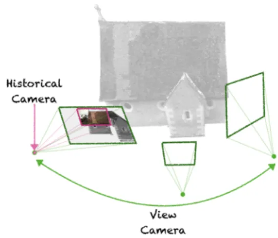
To visualize a photograph in a 3D model, we define two cameras (Figure 2). A camera designated as the historical camera, which models the camera used to acquire the picture. The visualization through this camera will be as looking directly at the image. This camera has a distortion model that describes the geometric distortion of the photographic image acquisition process. Simultaneously, a second camera is responsible for the navigation through the 3D environment and is specified as theview camera. It is the camera utilized during the rendering process and allows all the movements within the scene, e.g. zooming, translating, rotating, etc.
Figure 2. A historical camera has a fixed viewpoint, representing a snapshot of the photographed scene. A view camera is capable of changing its viewpoint, allowing it to navigate through the 3D
scene.
While the view camera is free to navigate between different viewpoints, we are interested in the case where the view camera matches the position of the historical camera. If so, we apply a projective texturing approach and reproject pixel-accurate the image into the scene (Segal et al., 1992, Debevec et al., 1998). To provide additional context from the 3D scene to the historical photograph, we zoom out the view camera. Since the distortion function is only properly defined inside the domain of the image (Section 4), we extend the distortion model from the historical camera with an extrapolation approach. This model is consequently used in the view camera to achieve zooming out from the image.
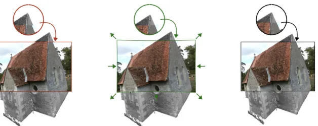
A comparison between the use of a pinhole model and a distorted model for both historical and view cameras is shown in Figure 3. If the distortion of the camera that acquired the photograph is not considered, then the view camera and the historical camera can use a pinhole camera model (Figure 3a). Nonetheless, misalignments between the picture and the scene would be noticeable. Considering formerly the distortion on the photo, a distorted camera model can be applied to the historical camera (Figure 3b). It corrects previous misalignments but
(a) A pinhole model for both view and historical cameras. Misalignments between picture and scene are visible, as the distortion of the camera that acquired the image is not taken into account.
(b) A pinhole model for the view camera and a distorted model for the historical camera. Misalignments are corrected but the image is
deformed (green arrows emphasize the pincushion distortion of the historical
photograph).
(c) A distorted model for both view and historical cameras. Misalignments are corrected and the image preserves its rectangular shape because the scene is viewed through a camera with distortion.
Figure 3. Comparison of projective texturing with different camera models for historical and view cameras. the image is deformed following the distortion model from the
historical camera. Our method uses a distorted camera model for both view and historical cameras (Figure 3c). Hence the 3D world is viewed through a distorted view camera. This technique preserves the unaltered rectangular version of the photograph without possible image misalignments or image deformations.
4. DISTORTION MODEL DEFINITION For a given pixel point p on a picture, its distortion can be seen as the geometric deviation between its actual coordinates and the ideal coordinates. Many distortion models have been developed to encode this divergence of the pixel projections from the ideal pinhole camera model, e.g. radial, tangential, fish-eye, etc. In the case of moderate distortions, the simplest and most commonly used distortion model is arguably the radial distortion model, which is the one we will consider in this paper.
Figure 4. Visual depiction of defined radial distortion model.
To allow the user to observe some context of the 3D scene around the historical image, the view camera will need to be zoomed out. Thus, the distortion of the view camera will need to extend the definition of the distortion of the historical camera to points outside of the image domain (Figure 4). Indeed, distortion models are estimated by fitting their parameters to the observations of point correspondences in the image domain only. Thus the mathematical distortion model may be subject to overfit, oscillations or may even not be properly defined outside of the image domain. In this section, we describe a radial distortion model that is defined on the whole undistorted image space. A description of the variables used through this article is shown in Table 1.
Variables Description p = (x, y) Undistorted image point in pixels pd= (xd, yd) Distorted image point in pixels
c = (cx, cy) Center of radial distortion
ki Radial distortion coefficient
r =|p c| Undistorted radial distance rd=|pd c| Distorted radial distance
rimg Image radial distance
rmax Maximum radial distance
rext Start of extrapolation radial distance
d(r) Radial distortion function d0(r) Derivative of d(r)
d(r) Extrapolation of d(r) d 1(r) Inverse of d(r)
Table 1. List of mathematical variables. 4.1 Radial Distortion
The radial distortion is an inward or outward displacement of the pixel point p. This movement is only performed along a radial direction from the distortion center c. It can be expressed by a polynomial series (Fraser, 2001):
where r is the radial distance in pixels to the distortion center, denoted as r2=
kp ck2= (x c
x)2+ (y cy)2and
P (X) = k1X + k2X2+ k3X3+ ...is a polynomial. Then the
relationship between an ideal (undistorted) image point p and its distorted image point pdis:
pd= c + d(r)p c
r = p + P (r
2)(p c) (2)
4.2 Extrapolation of Distortion
The polynomial function d(r) is defined for all values of r (Equation (1)). Nevertheless, it has been estimated using observations only on the image domain [0, rimg], where rimg
represents the radius that includes the complete image. Hence, values on r > rimgare likely subject to overfit and oscillations.
In this work, we are interested in a bijective distortion transformation, where d(r) is a non-decreasing continuous function. To achieve this, we limit the domain of d(r) to a range of [0, rext], with rext< rmax. We designate rmaxas the
smallest positive root of the derivative d0(r).
For values r > rext, we introduce a linear extrapolation
approach (Figure 5). We denote the starting point of extrapolation as rext 2 [0, rmax], where a complete distortion
correction can be achieved when rext rimg. Accordingly, we
extend the definition of the distortion function as d(r): d(r) = ( d(r) if r 2 [0, rext]] r·d(rext) rext if r > rext (3)
Figure 5. Example of the behavior of the radial distortion model. dimg(r), dext(r), dmax(r)show three possible extrapolation
candidates for d(r), depending on the value where the extrapolation starts (respectively of rimg, rextand rmax).
In the extrapolated domain r > rext, this achieves an affine
transform. The camera behaves there as a pinhole camera with modified intrinsic parameters. The focal length and skew are multiplied by (1 + P (r2
ext))and the principal point p0 is
translated by P (rext)(p0 c). if r > rext, pd= c + r· d(rext) rext p c r = p + P (r 2 ext)(p c) (4) 4.3 Inverse Distortion
When the objective is to determine the radial distance r of an undistorted point, the goal is to find an inverse transformation for Equation (3). For values r 2 [0, rext], an analytical
solution is difficult to be calculated. From an optimization point of view, an iterative approach can be introduced. Using Newton–Raphson’s method, with a quadratic convergence rate (Benligiray, Topal, 2015), an approximation of r can be obtained through the iteration:
if r2 [0, rext],
r(n+1)= r(n)+rd d(r
(n))
d0(r(n)) (5)
If r(0) = r
d · d(rrextext) is defined as the initial guess (i.e. it
guarantees that r(0) starts in the definition domain [0, r max]
of d(r)). Iteratively it can be refined until the solution for r converges.
5. RESULTS 5.1 Implementation
An implementation pipeline like the one proposed by (Lorenz, D¨ollner, 2008, Lorenz, D¨ollner, 2009) is capable of applying a piecewise projective approximation of the distortion model established in Section 4. Nonetheless, its usage is limited because of the requirement of geometry shaders, i.e. not found in a web graphics application. In this work, we explore a different approach to extend the distortion model for an online context. We use two pipelines (Figure 6) for the specific requirements of each category of 3D models (i) point cloud (Figure 6a); (ii) mesh (Figure 6b). We have implemented both of them using the three.js OpenGL rendering library4. As
input, it is required:
(i) An historical photograph depicting a snapshot of a geographical scene.
(ii) Theimage calibration data that maps the coordinates in the photo to the ones in the 3D scene. It contains the following information:
Extrinsics: a transformation (rotation and translation) from 3D world coordinates to the 3D camera’s local coordinates.
Intrinsics: a transformation from 3D camera’s coordinates into the 2D image coordinates (includes principal point and focal).
Distortion: a mathematical function that models the geometric deviation from the ideal pinhole model of the camera’s intrinsic parameters.
(iii) A 3D model that enables the navigation of the view camera in the 3D environment. It is important to notice that the accuracy of the 3D scene is not relevant to our method. If a single image is unprojected and the view camera is placed at that photo’s position, then the scene information is not necessary at all. Any geometry that fills the viewport can be used equally.
(a) One-pass rendering, where the distortion is applied to the vertices of
the scene and the reprojection of the image. (b) Two-pass rendering, where the distortion is applied to the reprojectionof the image in the first pass. In a second pass, the inverse distortion is applied to the texture of the whole viewed scene.
Figure 6. Implemented pipelines. 5.1.1 One-Pass Rendering A point cloud is a collection
of data points in the 3D space sampled from an object. For the distortion of this type of scene, the simplest approach can be followed by a one-pass rendering method. The distortion model, from the view camera, is applied to the vertices of the 3D function when computing their projections on the screen in the vertex shader. Additionally, on the reprojected image, the distortion model from the historical camera is used when sampling the image as a texture in the fragment shader. Inverse distortion is not needed. The result is the distortion in both view and historical cameras at the same time. The pipeline is sketched in Figure 6a.
(a) One-pass rendering only distorts the vertices of the triangles,
but their edges remain straight.
(b) Two-pass rendering distorts all the viewed scene. Thus, both vertices and edges in the triangle
are distorted.
Figure 7. Comparison between one-pass and two-pass pipelines. A wireframe tessellated plane has been put in front of the
viewed scene to showcase the two methods.
5.1.2 Two-Pass Rendering A mesh is a structural model containing polygons, commonly triangles. One-pass rendering for these types of models is not suitable since vertices would get distorted but not their edges (Figure 7). Hence we are applying a two-pass rendering that is acknowledged in computer graphics as render-to-texture (Szirmay-Kalos et al., 2008). In the first pass, the scene is rendered as usual with a pinhole camera. The distortion model from the historical camera is used in the reprojection of the image. The whole view of the scene is saved as an input texture for the second pass, where it will be inversely distorted. The distortion model used for the second pass is the one defined for the view camera. Following this path, the historical photograph is distorted in the first pass and the viewed scene in the second pass. The pipeline is illustrated
in Figure 6b. 5.2 Dataset
We have selected two distinguished image collections (Table 2). The first dataset is a modern acquisition of terrestrial close-range images. These pictures have been acquired under controlled conditions, implying that the pictures were taken with fine large overlaps between each other to generate an accurate 3D reconstruction. The second one is a historical collection of nadir aerial images. These photographs suffer from all the possible difficulties that a historical collection may have. The image quality is not optimal because is only a scanned version and the error of the scanner is introduced. Also, its photogrammetric process is not obvious since the rate of overlaps is low, i.e. when films where used, the overlap was limited because of its cost. Therefore its 3D reconstruction cannot be optimal as well as the calibration information that is produced because the multiplicity of tie points is low.
Name Point of View Date No. Images Example
Maurepas Terrestrial 2015 30
Frejus Aerial 1966 15
Table 2. Overall description of datasets (credits: IGN/ENSG acquisitions.)
5.3 Variation of Extrapolation Radius
As mentionned in Section 4.2, the starting extrapolation point rext can vary in a range of [0, rmax]. When rext = 0
(Figure 8a), a perspective view can be achieved since there is no distortion applied at all. A complete distortion correction can be seen only when rext rimg. Based on our experience
with the different tested datasets, the case of rext = rimg is
the best configuration for the visualization of a specific image (Figure 8c). It allows the correction of distortion without any overfit like when rext> rimg(see Figures 8d and 8e).
To move from the visualization of one imageA to another imageB, the method of image interpolation can be used (Seitz, Dyer, 1996). If it is assumed that rext = rimgAwhen imageA
(a) rext= r0. (b) rext2 [r0, rimg]. (c) rext= rimg. (d) rext2 [rimg, rmax]. (e) rext= rmax.
Figure 8. Outcomes in the employed datasets when the extrapolation radius rextvariates in the range of [0, rmax](the circle with the
black shading has radius rextand is only for illustrative purposes).
is visualized, then the interpolation from rimgA to rimgB is
needed. Along with this, the distortion coefficients kialso have
to be interpolated. This can cause a dizzy experience for the viewer. We instead propose to reduce the value of rext= 0(see
Figure 8a) to achieve a perspective view. The movement from one photograph to the other can be made with this value. When the view camera arrives at the desired position, the value of rext
can be continuously increased from 0 to rimgB.
6. CONCLUSIONS
In summary, the main contribution of this work is the definition of a distortion model applied through the whole undistorted image space. It enables the camera used in the 3D environment to inherit and extend the distortion model from the camera sensor used to take the historical photograph. Therefore, this method provides a formal procedure for achieving a 3D visualization of historical images that presents geometric distortions on scenes composed of triangular meshes and/or point clouds.
Here it is only exhibited the extrapolation approach from a radial model, but our technique could be extended to other existing distortion models. To show the effectiveness of our method we will tackle as future work the definition of a quality metric. Until now, we suggest the possibility of an objective quantity metric to examine the maximum displacement in pixels between the historical image and its view through the view camera (i.e. which should be close to zero). Subjective metrics could be also an alternative, but it requires proper experiment design and evaluation using final users as the test group. As additional future work, we propose to examine our method in larger historical datasets. Along with this, rather than reconstructing the 3D scene from the desired visualized photographs, it would be interesting to place the images in a 3D scene depicting the modern geographical environment. Furthermore, the exploration of the scene can be reached in immersive visualization. We recommend our method only for Virtual Reality since in Augmented Reality the optical view is not subjected to distortion (i.e. mainly minimized by the lens
manufacturer). Hence, rendering this type of reality with a distorted camera would not be ideal.
ACKNOWLEDGEMENTS
This study is funded by the French Research Agency ANR, in the framework of ALEGORIA ANR-17-CE38-0014-01 (Advanced Linking and Exploitation of diGitized geOgRaphic Iconographic heritAge) project (2018-2022).
REFERENCES
Baggett, M., Gibbs, R., 2014. Historypin and Pinterest for Digital Collections: Measuring the Impact of Image-Based Social Tools on Discovery and Access. Journal of Library Administration, 54(1), 11-22.
Benligiray, B., Topal, C., 2015. Lens distortion rectification using triangulation based interpolation. Advances in Visual Computing, 9475, 35–44.
Br´edif, M., 2013. Efficient View-Dependent Image-Based Rendering with Projective Texture-Mapping. ISPRS Annals of Photogrammetry, Remote Sensing and Spatial Information Sciences, II-3/W3, 7–11.
Brivio, P., Benedetti, L., Tarini, M., Ponchio, F., Cignoni, P., Scopigno, R., 2013. PhotoCloud: interactive remote exploration of joint 2D and 3D datasets. IEEE Computer Graphics and Applications, 33(2), 86–96, c3.
Debevec, P., Yu, Y., Borshukov, G., 1998. Image-based rendering of LOD1 3d city models for traffic-augmented immersive street-view navigation. Rendering Techniques ’98, Springer Vienna, 105–116.
Devaux, A., Br´edif, M., 2016. Realtime projective multi-texturing of pointclouds and meshes for a realistic street-view web navigation. Proceedings of the 21st International Conference on Web3D Technology - Web3D ’16, 105–108.
Fraser, C., 2001. Calibration and Orientation of Cameras in Computer Vision. Springer, Berlin, 95–121.
Goesele, M., Ackermann, J., Fuhrmann, S., Haunbold, C., Klowsky, R., Steedly, D., Szeliski, R., 2010. Ambient Point Clouds for View Interpolation. ACM Transactions on Graphics, 29.
Gortler, S. J., Grzeszczuk, R., Szeliski, R., Cohen, M. F., 1996. The lumigraph. Proceedings of the 23rd annual conference on computer graphics and interactive techniques - SIGGRAPH ’96, 43–54.
Gortler, S. J., Grzeszczuk, R., Szeliski, R., Cohen, M. F., 2001. Unstructured lumigraph rendering. Proceedings of the 28th annual conference on computer graphics and interactive techniques - SIGGRAPH ’01, 425–432.
Graf, N., 2017. sMapshot: geolocate our images on a virtual 3d globe. Spectrum Conference.
Levoy, M., Hanrahan, P., 1996. Light field rendering. Proceedings of the 23rd annual conference on computer graphics and interactive techniques - SIGGRAPH ’96, 31–42. Lorenz, H., D¨ollner, J., 2008. Dynamic mesh refinement on GPU using geometry shaders. Proceedings of the 4th international conference on Computer graphics and interactive techniques in Australasia and Southeast Asia - GRAPHITE ’06, 97–104.
Lorenz, H., D¨ollner, J., 2009. Real-time piecewise perspective projections. Proceedings of the Fourth International Conference on Computer Graphics Theory and Applications, 147–155.
Papadopoulos, S., Zigkolis, C., Kapiris, S., Kompatsiaris, Y., Vakali, A., 2010. ClustTour: city exploration by use of hybrid photo clustering. Int. Arch. Photogramm. Remote Sens. Spatial Inf. Sci., 20, 1617.
Segal, M., Korobkin, C., van Widenfelt, R., Foran, J., Haeberli, P., 1992. Fast shadows and lighting effects using texture mapping. ACM SIGGRAPH Computer Graphics, 26(2), 249–252.
Seitz, S. M., Dyer, C. R., 1996. View morphing. Proceedings of the 23rd annual conference on computer graphics and interactive techniques - SIGGRAPH ’96, 21–30.
Snavely, N., Seitz, S. M., Szeliski, R., 2006. Photo tourism: exploring photo collections in 3D. Proceedings of the 33th annual conference on computer graphics and interactive techniques - SIGGRAPH ’06, 835–846.
Spindler, M., Bubke, M., Germer, T., Strothotte, T., 2006. Camera textures. Proceedings of the Fourth International Conference on Computer Graphics Theory and Applications, 295.
Szirmay-Kalos, L., Szecsi, L., Sbert, M., 2008. GPU-Based Techniques for Global Illumination Effects. Morgan and Claypool.