HAL Id: hal-03022794
https://hal.archives-ouvertes.fr/hal-03022794
Submitted on 24 Nov 2020
HAL is a multi-disciplinary open access
archive for the deposit and dissemination of
sci-entific research documents, whether they are
pub-lished or not. The documents may come from
teaching and research institutions in France or
abroad, or from public or private research centers.
L’archive ouverte pluridisciplinaire HAL, est
destinée au dépôt et à la diffusion de documents
scientifiques de niveau recherche, publiés ou non,
émanant des établissements d’enseignement et de
recherche français ou étrangers, des laboratoires
publics ou privés.
mechanoresponsive electrical humidity sensors with
on-demand performances
Marco Squillaci, Marc Antoine Stoeckel, Paolo Samori
To cite this version:
Marco Squillaci, Marc Antoine Stoeckel, Paolo Samori. 3D hybrid networks of gold nanoparticles:
mechanoresponsive electrical humidity sensors with on-demand performances. Nanoscale, Royal
Soci-ety of Chemistry, 2019, 11 (41), pp.19319-19326. �10.1039/C9NR05336K�. �hal-03022794�
ARTICLE
Received 00th January 20xx, Accepted 00th January 20xx DOI: 10.1039/x0xx00000x
3D Hybrid Networks of Gold Nanoparticles: Mechanoresponsive
Electrical Humidity Sensors with On-Demand Performances
Marco Antonio Squillaci, Marc-Antoine Stoeckel and Paolo Samorì*
We have engineered macroscopic 3D porous networks of gold nanoparticles (AuNPs) chemically interconnected by di-thiolated ethylene glycol oligomers. The formation of such superstructures has been followed by means of UV-Vis spectroscopy by monitoring the aggregation-dependent plasmonic band of such nanomaterials. The controlled chemical tethering of the AuNPs with di-thiolated linkers possessing a well-defined contour length rules the interparticle distance. The use of ad-hoc linkers ensures charge transport via direct tunneling and the hygroscopic nature of the ethylene glycol backbone allows interaction with moisture. Upon interaction with water molecules from the atmosphere, our 3D networks undergo swelling reducing the tunnelling current passing through the system. By exploiting such a behavior, we have devised a new approach for the fabrication of electrical resistive humidity sensors. For the first time we also introduce a new strategy to fabricate stable and robust devices by covalently attaching our 3D networks to gold electrodes. Devices comprising both 4 (TEG) or 6 (HEG) ethylene glycol repetitive units combined with AuNPs exhibited (i) unprecedented high response speed (~26 ms), (ii) short recovery time (~250 ms) in absence of any hysteresis effect, (iii) a linear response to humidity changes characterized by a highest sensitivity of 51 kΩ•RH(%)-1 for HEG- and 500 Ω•RH(%)-1 for TEG-based devices. The employed
green solution processing in water and the extreme robustness of our 3D networks make them interesting candidates for the fabrication of sensors which can operate under extreme conditions and for countless cycles.
Introduction
The presence of moisture in air is fundamental to guarantee the comfort in living and working environments. In standard living conditions, the relative humidity (RH) should be normally kept around 50% with a temperature of 20-25° C. However, for specific applications these conditions may vary; for example, the RH must be constantly set at 38% in class-10 clean rooms, 60% in hospital operating rooms and close to 0% for operating certain equipment, such as high impedance electronic circuits, electrostatic sensitive components, high voltage devices, fine mechanisms, etc.1 The growing demand of devices to monitor
and control the humidity levels led to an increasing effort towards the development of smaller, more performing and more reliable humidity sensors which can be integrated in other equipment such as air conditioners, humidifiers, etc, without affecting their price and size. Hitherto, different architectures, design and sensing mechanisms have been explored in order to improve the sensing performances. The device’s readouts can either be directly electrical, such as changes in devices’s resistance,2 capacitance3 and gate-effect in field-effect
transistors,4 or indirect, such as changes in the optical
characteristics5, 6 or in the mass7. Hitherto, different active
materials have been explored, including ceramics,8-11
carbon-based materials,12 composites13-15 and organic/polymeric thin
films5 and supramolecular nanostructures.16, 17 Chemical
sensing occurs via recognition events between a supramolecular receptor and a specific analyte. The full decoration of the surface of functional low-dimensional nanostructures, exhibiting high surface-to-volume ratios, with the receptors of the chosen analyte is a viable route towards harnessing improved sensing.
Gold nanoparticles (AuNPs) represent extremely versatile low-dimensional scaffolds for the fabrication of sensing devices relying on their special physico-chemical characteristic.18, 19
Such nanomaterials can be synthesized by bottom-up approaches in solution, by following facile and well-established procedures, thereby allowing to achieve control over their size on the nanometer scale, which cannot be easily attained with lithographic procedures.20, 21 Moreover, gold possesses a
unique chemical reactivity: it can form covalent bonds with thiol molecules, enabling the formation of so-called self-assembled monolayer on the metal’s surface.22, 23 This chemical affinity
between gold and thiols can be exploited to functionalize such materials with a wide range of receptors to trigger selective interactions with specific analytes in solution or in gaseous form.24-27 In addition, AuNPs larger than 2-3 nm show metallic
electrical characteristics28 that can be exploited for the
fabrication of electrical devices.29 Hitherto, AuNPs gas sensing
devices have been reported for the detection of volatile organic compounds such as toluene,30, 31 1-propanol,32 acetone or
University of Strasbourg, CNRS, ISIS UMR 7006, 8 Allée Gaspard Monge, F-67000 Strasbourg, France.
ARTICLE
Journal Name
2 | J. Name., 2012, 00, 1-3 This journal is © The Royal Society of Chemistry 20xx
cyclohexane33 but very few examples of humidity sensing have
been reported34. In 2014, Lee et al. reported on high sensitive
humidity sensors made by thick films of AuNPs (4-6 nm diameter) coated with a layer of dopamine as water absorbing material and transducer of the amount of absorbed water. Such devices displayed a remarkable decrease of the recorded resistance up to 4 orders of magnitude upon increasing the humidity from 10 to 90% because of the interaction between water and dopamine that generates OH- ions as charge carriers
embedded within the films. However, such process requires time to equilibrate, leading to slow response speed (5 s absorption and 10 s desorption).35 Several application require
real-time and continuous monitoring of environmental humidity, therefore the development of reliable high-speed sensors with ad-hoc characteristics is of primary importance. Here we have devised a novel device architecture and exploited it as resistive humidity sensors. Such devices are made by all-covalent 3D networks of AuNPs connected with oligoethylene glycol di-thiols (OEG) linkers. The presence of two thiol groups in each molecule guarantees the formation of extremely robust and mechanically stable aggregates in which the nanoparticles are covalently linked and the interparticle distance is determined by the length of the ligands backbone. The hygroscopic nature of the OEG also allows to reversibly absorb/desorb water molecules from the atmosphere. Upon absorption of water molecules, the AuNPs-OEG 3D structure undergoes swelling, yielding an increased interparticle distance which dramatically affects the electrical resistance through system. We also show that by using different OEGs chain length it is possible to tune the sensors characteristics to meet different application requirements. On this regard, devices based on shorter OEG chains feature low resistance and electrical noise, allowing to be powered by simple setups and just 20 mV. Such devices exhibit a highest sensitivity of 500 Ω RH(%)-1 and are suitable for low costs and low consumption
high-speed equipment (e.g. portable devices). On the other hand, by employing slightly longer OEG backbones it is possible to dramatically improve the minimum sensitivity up to 51 kΩ RH(%)-1 enabling extremely precise measurements. However,
the higher electrical resistance of the latter devices requires greater applied voltages and more sophisticated setups to be operated. In both cases the resulting devices features a state-of-the-art response time ~ 26 ms, a recovery time of ~ 250 ms and remarkable stability over time at environmental conditions.
Results and discussions
Figure 1: Molecular structure and corresponding nominal fully elongated length of di-thiolated TEG (4 repetitive units) and HEG (6 repetitive units).
We have synthesized water-dispersible AuNPs with the Turkevich method, obtaining spheres with an average diameter d = 8.6 ± 1.4 nm (determined by dynamic light scattering reported in ESI, Figure S1). With the purpose of fabricating electrical devices, we have focused our attention on two commercially available di-thiolated OEGs featuring 4 (TEG) and 6 (HEG) repetitive units (Figure 1) which are short enough to enable efficient charge tunneling between neighboring particles.
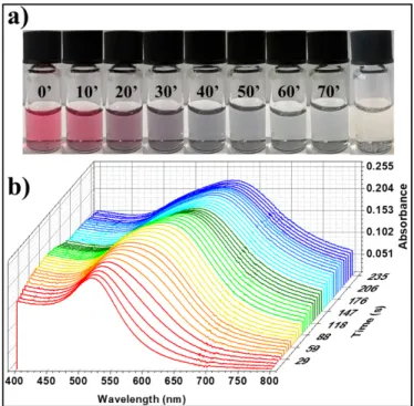
Figure 2: Optical evolution of AuNPs solutions upon addition of stoichiometric amounts of di-thiolated TEG. a) Series of optical photographs of the solution recorded with steps of 10 minutes and after one day (last picture). b) Evolution of the UV-Vis absorbance spectra within the first 4 minutes upon addition of the ligand solution.
The cross-link reaction, between the citrate-stabilized AuNPs and the OEG di-thiols, was performed upon addition of the diluted ligand solution directly to the water solution in which the AuNPs are grown, without further purification. The ligands solution was added in stoichiometric ratio with respect to the amount of gold nanoparticles present in solution. The use of a proper ratio between particles and ligands in solution is crucial to achieve the formation of stable cross-linked networks. A rough estimation of the needed amount of thiol groups can be obtained by purely geometrical considerations, as described in detail in the experimental section. According to these approximation, the cross-link reaction should be achieved by adding roughly 450 di-thiolated OEG molecules per each nanoparticle in solution. Such values were used as starting point to perform the preliminary studies on the AuNPs functionalization process with the chosen di-thiolated OEG ligands. During the cross-link reaction, the AuNPs are connected together into clusters which grow in size while the reaction occurs. Such aggregation has a dramatic impact on the optical properties of the AuNPs which lose their individual localized surface plasmon resonance (LSPR) characteristics as a result of the coupling with the neighbor particles. Such optical side-effect of the reaction represents an extremely powerful probe
to study the evolution of the cross-link reaction in-situ by using simple UV-Vis spectroscopy measurements to visualize sub-nanometer interparticle distance changes (Figure 2)
Figure 2 portrays the evolution in the optical properties of the AuNPs solutions upon addition of stoichiometric amounts of di-thiolated TEG at room temperature. Such measurements reveal several crucial information: (i) the red shift of the AuNPs LSPR band, accompanied by a broadening of the signal and by an increase of the background given by scattered light, represent clear evidences of the occurrence of aggregation, confirming that the cross-link reaction can occur under the chosen condition. (ii) The clear and colorless supernatant of the solution, resulting at the end of the reaction (last picture in Figure 2a), proves that the ratio between particles and ligands employed for the reaction is correct. Several control experiments have shown that the use of either excess or defect of ligands would lead to the simultaneous presence of precipitate and colored supernatant, because of the presence of unreacted AuNPs which aggregate (in the case of defect of ligands) or by ligands saturated AuNPs which are not connected to the networks (in the case of an excess of ligands). (iii) The same experiment, performed by using a slightly longer ligand (HEG instead of TEG), leads to the same optical evolution and final results, but features a lower kinetic, requiring six days instead of 20 hours to reach the final stage under the same conditions. The different kinetics of the cross-link reactions, observed by comparing TEG and HEG, could be ascribed to a lower reactivity of the thiol groups connected to longer linear chains or, more probably, to a higher solubility of the resulting networks which need to grow bigger to trigger the precipitation when longer ligands are employed.
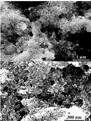
The dark precipitate found at the bottom of the vials, at the end of the cross-link reaction, and visible in the last vial in Figure 2a, was deposited by drop-casting on the basal plane of silicon substrate and characterized by SEM (Figure 3).
The SEM images displayed in Figure 3 show that the precipitate, resulting from the reaction between AuNPs and di-thiolated OEGs, features a 3D architecture in which the AuNPs are interconnected forming porous structures. Due to their size, the AuNPs-OEG networks are not soluble in any solvent, allowing to rinse the precipitate in water (or in any other solvent) in order to efficiently remove the residues of sodium citrate present as stabilizer for the AuNPs.
Figure 3: SEM images of AuNPs-TEG porous 3D networks.
Electrical characterization
The AuNPs-OEGs electrical characteristics were probed by deposing the networks on SiO2/Si substrates, pre-patterned
with interdigitated gold electrodes featuring a channel length (L) ranging from 2.5 to 20 µm with a channel width (W) kept constant at 104 µm. To ensure optimal packing of the AuNP
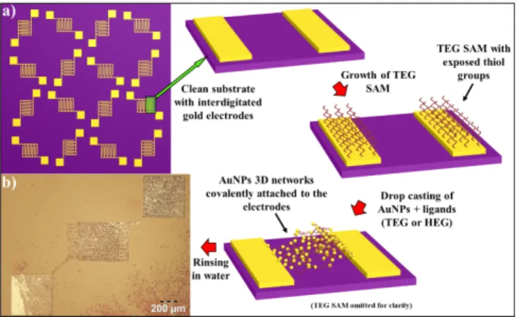
network at interface with the pre-patterned Au electrodes along with a high degree of film uniformity and more reproducible depositions, a two-step approach was pursued to covalently bridge the 3D AuNPs network to the pre-patterned electrodes. The first step consisted in the formation of a chemisorbed self-assembled monolayer (SAM) of di-thiolated TEG on the clean surface of SiO2 exposing interdigitated Au
electrodes. 36 TEG was chosen because its shorter contour
length makes it more rigid than HEG and, under the employed conditions, only one thiol group per molecule should react with the electrode. In this way occurrence of back-folding is prevented, ultimately resulting in electrode’s surface coated by a molecular monolayer exposing thiols groups.37 The second
step relied on the growth of the AuNPs-OEGs networks directly on the substrate’s surface, by drop-casting the AuNPs and the OEG solution immediately after mixing them. As displayed in Figure 2 the kinetic of the cross-link reaction between the NPs and the OEGs is fast enough to reach its end before the complete evaporation of the water solvent, allowing the growth of structurally defined 3D networks on the electrode’s surface. Our two-step approach is schematized in Figure 4.
ARTICLE
Journal Name
4 | J. Name., 2012, 00, 1-3 This journal is © The Royal Society of Chemistry 20xx
Figure 4: Optimized procedure for the fabrication on 3D AuNPs-OEG based electrical devices. a) Flowchart of the process. b) Optical micrograph of the resulting device.
This procedure allows, on the one hand to shield the electrodes from the di-thiolated OEGs needed to cross-link the AuNPs, and, on the other hand, to concentrate the AuNPs networks on in the interelectrodic gap, to ensure a good coverage inside the channel. Moreover, it guarantees the formation of a covalent link between the electrodes and the AuNPs networks, dramatically improving the stability of the electrical contact and increasing the mechanical robustness of the final devices. The optical micrograph in Figure 4b provides evidence that the employed procedure makes it possible to efficiently bridge the electrode channels as confirmed at smaller scales, by the SEM imaging (ESI, Figure S2).
Two terminal I-V electrical resistance measurements of such devices at room temperature, displayed an ohmic behavior with a linear dependence of the measured current respect to the applied bias (ESI, Figure S3). The statistical analysis on the electrical resistance was performed by preparing series of at least 4 samples (32 devices) per each employed ligand (TEG or HEG). For the sake of comparison, the same study was also performed on films of bare AuNPs (e.g. by drop-casting the pristine AuNPs solution without addition of the OEG ligands), prepared under the same conditions and on the same substrates, to be used as reference. The latter makes it possible to quantify the intrinsic resistivity of such system when the particles are in direct contact among each other, with no ligands in-between. The obtained results are summarized in ESI, Figure S4. They exhibit an average resistance of 34 ± 9 kΩ for the AuNPs-TEG networks and 430 ± 90 kΩ for the AuNPs-HEG devices, while the resistance of the bare AuNPs films was found to be 105 ± 7 Ω. The latter, being extremely low, can be considered as the intrinsic lowest resistance for such devices. Interestingly, the aforementioned device resistance has shown to be exponentially dependent by the nominal chain length of the employed di-thiolated OEG. By plotting the measured 2-terminal electrical resistance versus the nominal length of the ligands, it is possible to fit the experimental data by using a general exponential equation (Eq. 1):
𝑹 = 𝑹𝟎𝜷𝑳 (1)
where R = Resistance and L = Nominal ligand length.
The proportionality factor “β”, extracted from the fitting, amounts to 0.38 Å-1, indicating a strong dependence of the
resistance with the interparticle distance. Such value of β is too large for a hopping-like charge transport mechanism, the latter being typically characterized by β ~0.1 Å-1 and strongly confirms
the presence of a tunneling transport of the charge carriers through the networks.38 The found proportionality factor of our
systems is significantly lower compared to what usually reported for alkanethiol chains (where β usually amounts to ~ 1.0 Å-1) and is in a very good agreement with the results recently
published by Baghbanzadeh et al. on vertical tunneling junction through thiolated OEGs.39
The tunneling charge transport mechanism was also confirmed by performing electrical characterization of the devices at different temperatures. Electrical I-V measurements performed inside a cryostat at temperatures spanning from 80 to 300 K (ESI, Figure S5) revealed an extremely small dependency of the electrical resistance from the temperature. Moreover, the I-V curve retain their linearity over the whole range of explored temperatures confirming that the charge carriers are transported through a direct tunneling mechanism.40
Figure 5: Evolution of two-terminal electrical resistance with temperature for bare AuNPs and AuNPs-TEG networks.
The same behavior (e.g. minor dependence of the electrical properties on the temperature) was also found for the reference device composed by bare nanoparticles. However, by plotting the evolution of the measured device’s resistance at different temperature, it is possible to observe a reversed trend with respect to the case of AuNPs-OEG networks, as highlighted in Figure 5. Such finding can be easily explained: Direct tunneling is a moderate thermally activated process thus the resistance decreases with increasing temperature. Conversely, in a metal-metal junction the resistivity is given by the scattering of the charge carriers hitting the metal lattice; the increasing temperature determines an enhanced amplitude of the lattice’s vibrational modes, increasing the scattering of the charge carriers and, therefore the electrical resistance.
80 120 160 200 240 280 80 90 100 Bare Au NPs Au NPs + TEG Temperature (K) R e s is ta n c e ( W ) 1.2x10⁴ 1.4x10⁴ 1.6x10⁴ 1.8x10⁴
Humidity sensing
The resistance measurements of the AuNPs-TEG networks performed inside the cryostat is reported as red squares in Figure 5. It reveals the presence of a “bump” between 170 and 220 K where the resistance undergoes a slight increase and then decreases back returning to the initial trend. Careful investigation of the employed setup, have shown that, even if the cryostat is purged with nitrogen and constantly kept under vacuum (10-3 mBar) during the measurements, it is subjected to
small increase of inner humidity in the 170-220 K range of temperatures. The increased humidity was detected by the AuNPs-TEG networks but did not affect the measurements on bare AuNPs, which do not contain any receptor to interact with moisture. The same phenomenon was also observed for AuNPs-HEG networks in which the increased humidity has an even more dramatic effect, as highlighted in ESI, Figure S6.
Figure 6: Electrical resistive humidity sensors based on AuNPs-OEG 3D porous networks. a) Cartoon of the sensing process. b) Picture of the device setup used for the sensor's characterization. c) Device’s response to short pulses of humid air (RH ~ 70%) in ambient conditions (constant bias applied = 500 mV). Inset showing a zoom-in of the plot between 35 and 45 s.
As aforementioned, OEG backbone can absorb water molecules from the atmosphere determining a swelling of the chain. For the case of 3D AuNPs-OEG networks the tunneling current features an exponential dependence on the interparticle distance. Therefore, the swelling of the networks causes a dramatic increase in the electrical resistance. This process is schematized in Figure 6a. The actual humidity sensing performances were characterized by connecting the AuNPs-OEG based devices with a custom-made printed board circuit (PCB). This setup allows to perform electrical measurements
in-situ, does not requires the use of probes or micro-manipulators
and features multiple individual electrical connection making it possible to characterize multiple TEG and HEG devices at the same time (Figure 6b).
The data reported in Figure 6c shows the electrical response of AuNPs-HEG networks, over time, while applying a constant bias of 500 mV. During the measurement, short pulses of humid air (RH ~ 70%) were sent on the device’s surface with a frequency of 1 Hz. The results from similar experiments performed on AuNPs-TEG networks can be found in ESI, Figure S7, while ESI,
Figure S8 portrays the results obtained with slower and longer cycles to reach saturation of the device’s signal and to determine the stability of the output signal under different conditions.
The results displayed in Figure 6 highlight 3 major features: (i) the devices are stable for an indefinite amount of cycles (certainly exceeding a few hundreds), allowing to continuously measure the response without suffering from any loss of performances or bias stress (e.g. as evidenced by a stable baseline). (ii) The absorption of water molecules and the subsequent increase in electrical resistance is a totally reversible process, allowing the resistance to go back to its initial value in ~ 250 ms. (iii) The response to humid air is extremely fast as it occurs on the 26 ms timescale.
Device calibration
By taking advantages of their humidity-dependent resistance, the fabricated device can be employed as resistive humidity sensors for real word applications. Such step obviously requires a calibration of the device’s characteristics at different humidity values. The calibration of the devices was performed by recording the evolution of their electrical resistance upon exposure to different humidity values by placing the samples in a sealed chamber with controlled humidity and constant temperature, in presence of a commercial humidity meter to be used as a reference.
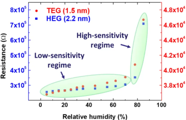
Figure 7: Calibration curves of AuNPs TEG and HEG based humidity sensors.
Representative calibration curves for AuNPs-TEG and -HEG network-based device, within the humidity range from 5% to 85% relative humidity, can be found in Figure 7.
The calibration curves, reported in Figure 7, were recorded by connecting the AuNPs-TEG and -HEG based devices, with two separated electrical channels, to apply a constant bias (20 mV for TEG and 500 mV for HEG based devices) and by continuously recording their electrical resistance, at a constant temperature of 22°C. Both devices exhibited a linear dependence of the measured electrical resistance with the environmental humidity in the range 0-70% RH with a dramatic change of slope above
ARTICLE
Journal Name
6 | J. Name., 2012, 00, 1-3 This journal is © The Royal Society of Chemistry 20xx
70% RH. Therefore, it is possible to identify for both series of devices two regimes displaying different sensitivities: a low-sensitivity one which extends from 0 to ~ 70% RH and a high-sensitivity one covering from ~ 70% to 100% RH
Such finding is in strong agreement with the literature and it is due to the not linear hygroscopic characteristics of the OEGs backbone which exhibit a strong increase of the water up-take at humidity levels exceeding 70%. Such finding is in strong agreement with the literature and it is due to the not linear hygroscopic characteristics of the OEGs backbone which exhibit a strong increase of the water up-take at humidity levels exceeding 70%.41, 42
Interestingly, the calibration plot reported in Figure 7 shows similar behavior for both systems. However, a more careful look at the resistance scales reveals that the sensitivity (e.g. the slope of electrical resistance versus RH) is notably higher for HEG based devices, amounting to 678 Ω·RH(%)-1, compared to
32 Ω·RH(%)-1 recorded for TEG based devices, under the same
conditions. Such values refer to the low sensitivity range of the devices, e.g. between 0 and 70% RH and grow exponentially above such threshold of RH = 70% reaching the remarkable value of 51 kΩ·RH(%)-1 for HEG and 500 Ω·RH(%)-1 for TEG based
devices.
Conclusions
In summary, we have studied the formation of 3D porous networks of gold nanoparticles in solution by using short di-thiolated oligoethylene glycols as bridges to covalently connect the particles. The exploitation of the optical plasmonic properties of the starting nanoparticles allowed us to follow the cross-link reaction by optical characterizations, enabling a precise evaluation over the process and over the stoichiometric ratio between the reactants. Because of the hygroscopic nature of the employed ligands our 3D networks have shown responsivity to environmental humidity, undergoing structural changes upon interaction with water molecules.43 Such
structural changes causes a dramatic modification of the electrical resistance of the networks, therefore making such systems promising candidates as active materials for nanoscopic resistive humidity sensors. On this regard, proof-of-principles devices have been fabricated by employing two different di-thiolated linkers featuring 4 and 6 repetitive units. Our systematic study demonstrated that such a small difference in the backbone chain length (nominally 0.7 nm) yield a dramatic and predictable difference of the devices performances to meet different application requirements. The AuNPs-OEG 3D networks have shown great response upon exposure to moisture and have been characterized as humidity sensors, exhibiting state-of-the-art response speed12, 44
(response time ~26 ms), a recovery time of ~ 250 ms, combined with no hysteresis effect nor fatigue effect over hundreds of water absorption/desorption cycles. Significantly, our devices are extremely versatile, as they can operate from 0% RH to immersion in water and from 77 to ~300 K, without any modification in the sensing performances. The employed device
could, in principle, be supported on flexible substrates paving the way towards it future use as wearable humidity sensor.
Materials and methods
Materials. Chloroauric acid (HAuCl4 ·3H2O), sodium citrate
(HOC(COONa)(CH2COONa)2 ·2H2O), di-thiolated TEG (97% Mn =
226.36 Da) and di-thiolated HEG (97% Mn = 314.46 Da) were
purchased from Sigma-Aldrich. Milli-Q-grade water (18.2 MΩcm) was used for all the preparations.
Synthesis and functionalization
9 nm wide AuNPs were synthesized in water with the Turkevich were synthesized with the Turkevich method20 by placing a 150
ml of a 2.2 mM water solution of sodium citrate in a 3-neck round-bottom flask. The flask was kept under Ar atmosphere using a balloon and heated up to 100 °C. At this point 1 ml of a 25 mM water solution of HAuCl4 was added rapidly in the flask
under stirring (the solution turns yellow because of the presence of the HAuCl4). The solution was kept at 100 °C under
continuous stirring for 3.5 min before being left to cool down at room temperature. The functionalization between AuNPs and OEGs into 3D covalent networks was performed in solution by directly mixing the water solutions in which the AuNPs are grown with appropriate amount of OEG solution upon dilution 1:1000 in Milli-Q-grade water. To roughly estimate the needed amount of thiol groups needed for such reaction we started from purely geometrical considerations: first of all, by comparing our optical UV-Vis spectroscopy data with the literature we found that the concentration of our AuNPs starting solutions is 1.3 x 10⁻⁸ M (the extinction coefficient of
8.55 nm wide AuNPs stabilized with sodium citrate in water is ε = 5.14 x 10⁷ M-1cm-1).45 The diameter distribution of our AuNPs
was determined by dynamic light scattering in ESI, Figure S1 and amounts to ~9 nm. From theoretical and experimental studies on Au/thiolated SAMs, reported in literature, it is known that the maximum molecular density of alkanethiol SAMs, on flat Au [111], amounts ~ 4.5 molecules/nm2.46 By considering the
higher steric hindrance of PEG backbone, compared to aliphatic chains, and that for particles bigger than 5.2 nm the curvature radius is negligible at molecular scales,22, 47 it is possible to
conclude that the upper limit for the density of molecules in the AuNPs-PEG SAM is equal 4.5 molecules/nm2. Therefore, each
nanoparticle cannot react with more than 900 thiol groups. By knowing the concentration, size, and amount of active site for reaction with thiols group we could estimate an approximate stoichiometric ratio between AuNPs and OEGs solution to achieve the formation of stable networks. Such approximated values were then corrected and refined by characterizing with UV-Vis spectroscopy the supernatant solution resulting from the cross-link reaction, as explained within the main text and in Figure 2.
DLS measurements were performed with a Malvern “Zetasizer Nano ZS”. UV-Vis absorbance spectra of the solutions were recorded in standard 1 cm optical path quartz cuvettes using a JASCO V670 UV-Vis-NIR spectrophotometer. Optical images
were taken with an Olympus BX51 optical microscope. All scanning electron microscopy imaging was conducted using a FEI Quanta 250 FEG Scanning Electron Microscope (SEM), operated in high vacuum mode (pressure in 10-4 Pa range). The
electrical characterizations were performed by using a Keithley double channel source meter model 2636B, connecting the samples through to a custom made PCB board. Two commercial humidity sensors: SENSIRION SHT21 and Radio Spares 1364 Humidity-Temperature Meter, were employed as reference for the calibration during the electrical measurements. The study of electrical response over time for all our devices including AuNPs-TEG, AuNPs-HEG and bare AuNPs without ligands as control experiments, have been performed in air (RH ~ 30%) using a custom-made setup comprising of a PCB board connected to the samples’ electrodes through Indium wires as portrayed in figure 6B. A Keithley model 2636B source meter was connected to the PCB and employed to apply a constant bias over time while recording the electrical resistance. A manually actuated valve connected to a reservoir of humid air (RH ~ 70%) and located few centimeters above the samples’ surface was employed to send short pulses of humid air in a reproducible and controlled manner. Low temperature electrical characterizations were carried out in an Oxford Instruments Optistat DN-V cryostat operating in the range between 80 and 300 K (liquid N2).
Conflicts of interest
There are no conflicts to declare.
Acknowledgements
We thank Mrs. Kübra Yasaroglu for preliminary analysis on the electrical properties of the AuNP networks. This work was financially supported by EC through the ERC project SUPRAFUNCTION (GA-257305) and the Marie Sklodowska Curie ETN projects SYNCHRONICS 643238) and iSwitch (GA-642196), the ANR Equipex Union (ANR-10-EQPX-52-01), the Labex projects CSC (ANR-10LABX-0026 CSC) and NIE (ANR-11-LABX-0058 NIE) within the Investissement d’Avenir program ANR-10-IDEX-0002-02, and the International Center for Frontier Research in Chemistry (icFRC).
References
1. J. Fraden, Handbook of Modern Sensors, Springer-Verlag New York, 4th edn., 2010.
2. X.-M. Jiang, Z.-B. Yan, D. Liu, K.-F. Wang, G.-C. Guo, S.-Z. Li and J.-M. Liu, Chem Asian J, 2014, 9, 2872-2879.
3. H. P. Hong, K. H. Jung, J. H. Kim, K. H. Kwon, C. J. Lee, K. N. Yun and N. K. Min, Nanotechnology, 2013, 24, 085501. 4. F. Liang, L.-B. Luo, C.-K. Tsang, L. Zheng, H. Cheng and Y. Y.
Li, Mater Res Bull, 2012, 47, 54-58.
5. E. Kim, S. Y. Kim, G. Jo, S. Kim and M. J. Park, ACS Appl
Mater Interfaces, 2012, 4, 5179-5187.
6. W. C. Wong, C. C. Chan, L. H. Chen, T. Li, K. X. Lee and K. C. Leong, Sensor Actuat B-Chem, 2012, 174, 563-569.
7. J. Xie, H. Wang, Y. Lin, Y. Zhou and Y. Wu, Sensor Actuat
B-Chem, 2013, 177, 1083-1088.
8. E. Traversa, Sensor Actuat B-Chem, 1995, 23, 135-156. 9. C. Doroftei, P. D. Popa and F. Lacomi, Sensor Actuat a-Phys,
2012, 173, 24-29.
10. R. K. Kotnala, J. Shah, B. Singh, H. Kishan, S. Singh, S. K. Dhawan and A. Sengupta, Sensor Actuat B-Chem, 2008,
129, 909-914.
11. V. Jeseentharani, L. Reginamary, B. Jeyaraj, A. Dayalan and K. S. Nagaraja, J Mater Sci, 2012, 47, 3529-3534.
12. S. Borini, R. White, D. Wei, M. Astley, S. Haque, E. Spigone, N. Harris, J. Kivioja and T. Ryhanen, ACS Nano, 2013, 7, 11166-11173.
13. Y. Zilberman, R. Ionescu, X. Feng, K. Mullen and H. Haick,
ACS Nano, 2011, 5, 6743-6753.
14. W. D. Lin, H. M. Chang and R. J. Wu, Sensor Actuat B-Chem, 2013, 181, 326-331.
15. S. Pokhrel, B. Jeyaraj and K. S. Nagaraja, Mater Lett, 2003,
57, 3543-3548.
16. M. A. Squillaci, L. Ferlauto, Y. Zagranyarski, S. Milita, K. Mullen and P. Samori, Adv. Mater., 2015, 27, 3170-3174. 17. M. A. Squillaci, G. Markiewicz, A. Walczak, A. Ciesielski, A.
R. Stefankiewicz and P. Samori, Chem Commun, 2017, 53, 9713-9716.
18. E. S. Cho, J. Kim, B. Tejerina, T. M. Hermans, H. Jiang, H. Nakanishi, M. Yu, A. Z. Patashinski, S. C. Glotzer, F. Stellacci and B. A. Grzybowski, Nat Mater, 2012, 11, 978-985. 19. A. Carattino, M. Caldarola and M. Orrit, Nano Letters, 2018,
18, 874-880.
20. J. Turkevich, P. C. Stevenson and J. Hillier, J. Phys. Chem., 1953, 57, 670-673.
21. M. Brust, M. Walker, D. Bethell, D. J. Schiffrin and R. Whyman, J Chem Soc Chem Comm, 1994, DOI: 10.1039/C39940000801, 801-802.
22. J. C. Love, L. A. Estroff, J. K. Kriebel, R. G. Nuzzo and G. M. Whitesides, Chem Rev, 2005, 105, 1103-1169.
23. O. M. Bakr, B. H. Wunsch and F. Stellacci, Chem. Mat., 2006, 18, 3297-3301.
24. K. Saha, S. S. Agasti, C. Kim, X. Li and V. M. Rotello, Chem
Rev, 2012, 112, 2739-2779.
25. A. L. Ginzburg, L. Truong, R. L. Tanguay and J. E. Hutchison,
ACS Nano, 2018, 12, 5312-5322.
26. L.-K. Lin, A. Uzunoglu and L. A. Stanciu, Small, 2018, 14, 1702828.
27. C. Kunstmann-Olsen, D. Belic, D. F. Bradley, M. P. Grzelczak and M. Brust, Chem Mater, 2016, 28, 2970-2980.
28. C. N. R. Rao, G. U. Kulkarni, P. J. Thomas and P. P. Edwards,
Chemical Society reviews, 2000, 29, 27-35.
29. J. H. Liao, S. Blok, S. J. van der Molen, S. Diefenbach, A. W. Holleitner, C. Schonenberger, A. Vladyka and M. Calame,
Chem. Soc. Rev., 2015, 44, 999-1014.
30. H. Wohltjen and A. W. Snow, Anal Chem, 1998, 70, 2856-2859.
31. Y. Joseph, I. Besnard, M. Rosenberger, B. Guse, H. G. Nothofer, J. M. Wessels, U. Wild, A. Knop-Gericke, D. S. Su, R. Schlogl, A. Yasuda and T. Vossmeyer, The journal of
physical chemistry. B, 2003, 107, 7406-7413.
32. Y. Joseph, A. Peic, X. D. Chen, J. Michl, T. Vossmeyer and A. Yasuda, J Phys Chem C, 2007, 111, 12855-12859.
33. Y. J. Kim, Y. S. Yang, S. C. Ha, S. M. Cho, Y. S. Kim, H. Y. Kim, H. Yang and Y. T. Kim, Sensor Actuat B-Chem, 2005, 106, 189-198.
ARTICLE
Journal Name
8 | J. Name., 2012, 00, 1-3 This journal is © The Royal Society of Chemistry 20xx
34. G. Konvalina and H. Haick, ACS Applied Materials &
Interfaces, 2012, 4, 317-325.
35. H. C. Lee, C. Y. Wang and C. H. Lin, Sensor Actuat B-Chem, 2014, 191, 204-210.
36. D. J. Beesley, J. Semple, L. Krishnan Jagadamma, A. Amassian, M. A. McLachlan, T. D. Anthopoulos and J. C. deMello, Nat. Commun., 2014, 5, 3933.
37. H. B. Akkerman, A. J. Kronemeijer, P. A. van Hal, D. M. de Leeuw, P. W. M. Blom and B. de Boer, Small, 2008, 4, 100-104.
38. S. H. Choi, B. Kim and C. D. Frisbie, Science, 2008, 320, 1482-1486.
39. M. Baghbanzadeh, C. M. Bowers, D. Rappoport, T. Zaba, L. Yuan, K. Kang, K. C. Liao, M. Gonidec, P. Rothemund, P. Cyganik, A. Aspuru-Guzik and G. M. Whitesides, J Am Chem
Soc, 2017, 139, 7624-7631.
40. T. H. Zheng, W. C. H. Choy and Y. X. Sun, Adv Funct Mater, 2009, 19, 2648-2653.
41. J. A. Baird, R. Olayo-Valles, C. Rinaldi and L. S. Taylor, J
Pharm Sci, 2010, 99, 154-168.
42. H. M. L. Thijs, C. R. Becer, C. Guerrero-Sanchez, D. Fournier, R. Hoogenboom and U. S. Schubert, J Mater Chem, 2007,
17, 4864-4871.
43. N. Olichwer, A. Meyer, M. Yesilmen and T. Vossmeyer, J
Mater Chem C, 2016, 4, 8214-8225.
44. U. Mogera, A. A. Sagade, S. J. George and G. U. Kulkarni, Sci
Rep, 2014, 4, 4103.
45. X. Liu, M. Atwater, J. Wang and Q. Huo, Colloids and
surfaces. B, Biointerfaces, 2007, 58, 3-7.
46. L. H. Dubois and R. G. Nuzzo, Annu Rev Phys Chem, 1992,
43, 437-463.
47. M. J. Hostetler, J. E. Wingate, C. J. Zhong, J. E. Harris, R. W. Vachet, M. R. Clark, J. D. Londono, S. J. Green, J. J. Stokes, G. D. Wignall, G. L. Glish, M. D. Porter, N. D. Evans and R. W. Murray, Langmuir, 1998, 14, 17-30.