HAL Id: inserm-00542507
https://www.hal.inserm.fr/inserm-00542507
Submitted on 2 Dec 2010HAL is a multi-disciplinary open access archive for the deposit and dissemination of sci-entific research documents, whether they are pub-lished or not. The documents may come from teaching and research institutions in France or
L’archive ouverte pluridisciplinaire HAL, est destinée au dépôt et à la diffusion de documents scientifiques de niveau recherche, publiés ou non, émanant des établissements d’enseignement et de recherche français ou étrangers, des laboratoires
Transcostal high-intensity-focused ultrasound: ex vivo
adaptive focusing feasibility study.
Jean-François Aubry, Mathieu Pernot, Fabrice Marquet, Mickaël Tanter,
Mathias Fink
To cite this version:
Jean-François Aubry, Mathieu Pernot, Fabrice Marquet, Mickaël Tanter, Mathias Fink. Transcostal high-intensity-focused ultrasound: ex vivo adaptive focusing feasibility study.. Physics in Medicine and Biology, IOP Publishing, 2008, 53 (11), pp.2937-51. �10.1088/0031-9155/53/11/012�. �inserm-00542507�
Transcostal high intensity focused ultrasound: ex vivo adaptive
focusing feasibility study
J.-F. Aubry, M. Pernot, F. Marquet, M. Tanter and M. Fink
Laboratoire Ondes et Acoustique, CNRS UMR 7587,Université Paris VII, Inserm, ESPCI, 10 rue Vauquelin, 75005 Paris, France
Abstract. Ex vivo experiments have been conducted through excised pork rib with bone, cartilage, muscle and skin. The aberrating effect of the ribcage has been experimentally evaluated. Adaptive ultrasonic focusing through ribs has been studied at low power. Without any correction, the pressure fields in the focal plane were both affected by inhomogeneous attenuation and phase distortion and three main effects were observed: a mean 2 mm shift of the main lobe, a mean 1.25 mm spreading of the half width of the main lobe and up to 20 dB increase of the secondary lobe level. Thanks to time reversal focusing, a 5-dB decrease in the secondary lobes was obtained and the ratio between the energy deposited at the target location and the total amount of energy emitted by the therapeutic array was 6 times higher than without correction. Time reversal minimizes the heating of the ribs by automatically sonicating between the ribs, as demonstrated by temperature measurements using thermocouples placed at different location on the ribcage. It is also discussed how this aberration correction process could be achieved non invasively for clinical application.
1. Introduction
The use of high intensity focused ultrasound (HIFU) as a non invasive method for treating tumours is rapidly increasing. The first successful clinical trials have been performed in the early 90s by placing the therapeutic probe in contact with the organ to be treated: in contact with the eye for the treatment of glaucoma (Silverman et al 1991) and in contact with the prostate using trans-rectal introduction for both benign prostate hyperplasia (BPH) (Gelet et al 1993, Madersbacher et al 1994, Sanghvi et al 1996) and prostate cancer (Madersbacher et al 1995, Gelet et al 1996). These clinical treatments proved that it was possible to safely target tissues with ultrasound by inducing a rapid heating of the tissues located in the millimetric volume of the focal spot while leaving tissues on the propagation path relatively unaffected. The feasibility of using extracorporeal ultrasounds to treat tumours has been first demonstrated in organs such as the kidney (Valancien et al 1992) and the liver (terHaar et al 1998). Many extracorporeal clinical devices are now commercially available and can be divided in two groups: some rely on an ultrasonic monitoring using an echographic array inserted in the therapeutic probe (Wu et al 2004) and others rely on a magnetic resonance (MR) monitoring by inserting an MR compatible therapeutic probe in an MRI unit (Hynynen 1996, Vimeux 1999).
MR monitoring received FDA approval for clinical use in the treatment of uterine fibroids (Chan et al 2002, Tempany et al 2003, Stewart et al 2003) and research programs are currently conducting clinical trials for the treatment of breast tumours (Gianfelice et al 2003, Furusawa et al 2007), liver tumours (Okada et al 2006, Kopelman et al 2006), and bone metastases (Catane et al 2007).
Wu et al (2004) reported a total of 1038 patients with solid tumours treated with extracorporeal HIFU ablation under ultrasonic monitoring. This study included primary and metastatic liver cancer, malignant bone tumour, breast cancer, soft tissue sarcoma, kidney cancer and pancreatic cancer. In the same report, solid benign tumours such as uterine myoma, benign breast tumour, and hepatic hemangioma have also been treated with HIFU thermal ablation.
All these studies suggest that HIFU is a safe and feasible technique capable of complete tumour ablation. But in the case of liver, however, the presence of the rib cage is affecting the HIFU treatment planning: on
overheating on the ribs can be quite important. There are two ways for the ribs to damage the surrounding tissues: ribs absorb the ultrasonic energy because of their higher absorption coefficient than soft tissues and radiate heat to the surrounding tissues, and reflection of the therapeutic beam at the bone-tissue interface can induce undesired constructive interferences in the surrounding tissues. In vivo measurements of temperature elevation on pork ribs have been reported by Daum et al (1999) thanks to MR temperature monitoring: temperature elevation during sonication was 5 times higher on the ribs than in the intercostal space.
Damage to the skin during liver treatment has thus been reported (Wu et al 2004a, b, Kennedy et al 2004, Li et al 2007). Li et al (2007) reported skin burns for all of the 17 patients that were treated, most of which located on the skin directly in the pathway of ultrasound (ventral side) but in three cases skin burns were also located on the opposite side (dorsal side). Such dorsal skin burns might be explained by the fact that the ribs surrounding the chest have a high absorption coefficient and are also heating in the contra lateral side and by the fact that the acoustic pressure field might have exceeded the required dose for thermal ablation: focal peak intensities up to 5000W.cm-2 were reported with up to 30s continuous exposure. To overcome this problem, prior to the treatment, Wu et al (2004b) resected a portion of the ribs overlying the targeted region of the liver in order to provide an acoustic window: as a single-element therapeutic transducer was used in this study, it was indeed impossible to avoid ultrasonic reflection of the ribs by adaptive focusing.
It has been proposed in the late 90s that the liver could be treated by using a phased array to sonicate between the ribs or bones (Mc-Gough et al 1996, Botros et al 1997, 1998) but it could not be experimentally tested at that time. Civale et al (2006) recently lowered the temperature of the ribs during sonication by switching off up to three elements of a linearly segmented HIFU transducer made of 10 elements: a temperature rise of up to 1K was measured on the skin surface when all segments were active; this rise was reduced to approximately 0.2K when three segments were switched off. Even though no focal lesions were induced and the number of active elements was not sufficient for a clinical application, this study confirmed the proof of concept introduced by Mc-Gough et al (1996) and Botros et al (1997). Multi element phased arrays made of hundreds of elements have since been developed (Daum et al 1998, Chapelon et al 2000, Pernot et al 2003, Ebbini et al 2006, Tanter et al 2007) making it possible to focus through the intercostals space, as will be shown in this paper.
In this study, a high power 200-element phased array is used to investigate the influence of the presence of ribs on HIFU treatment. In a first part the defocusing effect of the ribs will be experimentally measured in vitro and an adaptive focusing technique (time reversal) will be introduced in order to decrease this effect. Thanks to temperature measurements on the ribs it will be shown that the overheating of the rib cage can be dramatically reduced by time reversal techniques.
2. Materials and methods 2.1 Transducer
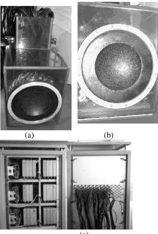
A quasi-random sparse array has been constructed in house. It has been made of 200 high power piezocomposite single elements, as seen on figure 1. The transducers have been mounted on a spherical surface (figure 1b) with a semi random distribution in order to minimize the side lobe level in the focal plane as well as the pressure level in the near field (Pernot 2003). The 8mm diameter individual transducers were designed to support a maximum output intensity of more than 40 W/cm² during 5 seconds at a 1MHz central frequency.
(a) (b)
(c)
Figure 1: 200 elements sparse array prototype and the electronic system. (a) The waterproof plastic box contains the 200 electrical matching boxes. (b) Front view of the array: the transducers are mounted on a spherical surface. (c) High Power electronics (individual channels)
The system was driven by 200 fully programmable individual electronic channels with 120 emitting channels and 80 emitting and receiving channels (18W per channel with a 40 output impedance).
2.2 Experimental setup
A freshly excised pork rib cage(figure 2c) has been put in front of the array so that it was partially shadowing the beam(figure 2 a and b) as would be the case in vivo. The rib cage was kept intact, with flesh and skin. The whole experiment was immersed in degassed and deionised water.
(a) (b) (c)
A PVDF hydrophone (Onda Corporation, 200µm active surface) was mounted on an automated 3D gantry system capable of motion in three orthogonal linear directions (Newport Motion controller MM4006). Pressure was recorded on the hydrophone for each position as a function of time by using one of the receive channels of our electronics, so that only 199 elements could be used to generate the pressure field. Once the position of the geometrical focus had been established, acoustic field measurements were made in the focal plane from –30mm to +30mm in both X and Y axis with a step size of 0.2mm in both axes. For each position, pressure was averaged over five sets of measurements before being stored in memory. 2.3 Temperature measurements
In order to investigate the thermal effect of the ultrasonic beam on the ribs, temperature measurements were made at various locations on the ribs and in the intercostal space with thin thermocouples (Iron-constantan, 40 µm diameter, PhysiTemp Corp). Thermocouples were inserted inside the tissues under the skin and muscles using a needle and after insertion the needle was removed so that the thermocouples were covered by a thin layer of tissues to avoid the effects of acoustic streaming and direct contact with water. Five thermocouples were inserted on the ribs, between the bone and the surrounding tissues and seven thermocouples were inserted in the intercostal space. Temperature rises were recorded on a PC board.
2.4 Simulations
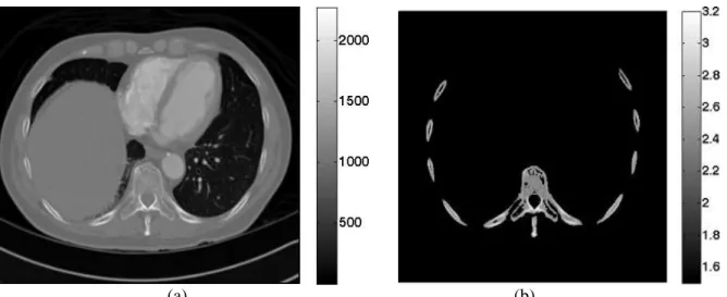
2D finite difference simulations have been performed in order to better understand the way the acoustic beam is affected by the ribs. Simulations were performed with a finite differences software called Acel. Acel is a FDTD numerical code developed at the Laboratoire Ondes et Acoustique. In this paper, the 2D mixed Fluid – Solid wave equation has been used in order to take into account mode conversions at the bone water interfaces. A 2D image of the ribs has been extracted from a 3D CT scan of a human thorax and is displayed in figure 3b.
From high resolution computed tomography (CT) images, a 2D portion of the chest wall has been extracted. As previously described in Aubry et al (2003), the porosity map () can be directly deduced from the raw CT data.
Then, the acoustical properties of the ribs are determined using mixture laws in a biphasic medium (bone/water). The mass density is easily deduced from porosity by :
w ater 1 bone (eq. 1) with 3 w ater 1 0 0 0 k g /m and 3 b o n e 2 1 0 0 k g /m . (Williams 1992)According to Carter and Hayes (1977), in a first approximation, a linear relationship may be assumed between velocity mass density, so that a linear relationship can be assumed between velocity and porosity: For longitudinal waves: clongi cw ater
cbone_longi cw ater
1
, (eq. 2)with cw ater 1500 m /s and cb o n e_ lo n g i 3 2 0 0 m /s (Goss et al. 1980) For transverse waves: cb o n e_ tran s 1 8 0 0 m /s. (Metha et al. 1997)
(a) (b)
Figure 3: 2D raw data in Hounsfield units (a) and the corresponding 2D longitudinal speed of sound map in mm.µs-1 (b)
Simulations were conducted at a 1MHz central frequency. The corresponding wavelength was 1.5mm. The simulation grid was set to one tenth of a wavelength. In order to meet the stability criteria, the temporal step must meet the following inequality :
r m ax ( ( )) 2 x t c r (eq. 3)
where x is the spatial step of the grid. The temporal step was thus set to 0.0366 µs.
The experimental setup was reproduced: an acoustic source was located at the geometrical focus of spherical array (120mm curvature). The propagation of an impulse (3 arches at 1 MHz central frequency) from the source to the array was simulated and the corresponding signals received by each element of the array were recorded. Even though the simulation was realised in 2D, the sizes of the receiver Spatial distribution of pressure was recorded regularly in order to reproduce a movie of the propagation of the beam through the ribs.
3. Results
3.1 Acoustic field of the beam
Once the geometrical focus of the array had been determined, the hydrophone was set to this position. Each element of the array emitted a narrow band signal (50 periods) and the corresponding signals were recorded by the hydrophone and stored in memory. These signals are displayed in figure 4 a. Using spatial reciprocity, they correspond to the set of signals that would have been received on the array of transducers if a small ultrasonic source located at the hydrophone position had been emitting a 50 periods signal. In order to evaluate the influence of the ribs, the normalized peak to peak amplitude of the signals is displayed in figure 4b. The amplitude received by each transducer is presented with a colour coding and displayed at the location of the transducer. One can see that even though the ribs were placed almost vertically, the pattern is not striped but quite complex due to the fact that the ribs are not perfectly linear and to reflection and diffraction effects between the ribs and the array.
Y P o s it io n ( m m ) 0 0.1 0.2 0.3 0.4 0.5 0.6 0.7 0.8 0.9 1 Y P o s it io n ( m m ) Y P o s it io n ( m m ) 0 0.1 0.2 0.3 0.4 0.5 0.6 0.7 0.8 0.9 1 0 0.1 0.2 0.3 0.4 0.5 0.6 0.7 0.8 0.9 1 (a) (b)
Figure 4: Signals received at the geometrical focus (a) and corresponding amplitude distribution (b). The shadowing effect of the ribs is confirmed by the simulations: an acoustic source was located at the geometrical centre of the array and emitted an impulse. Part of the wave front was reflected by the bone, so that the transmitted wave front was almost binarized: the amount of energy going through the ribs was almost negligible. The ratio between the amplitude of the waves propagating between the ribs (intercostals wave) and the waves propagating through the ribs (transcostal wave) was equal to 6.03 in the experiment and to 7.04 in the simulation.
Pressure Amplitude Intercostal waves (A.U.)
Pressure Amplitude Transcostal waves(A.U.)
Ratio
Experiments 5.89 42%, 0.98 52% 6.03
Simulation 5.88 32% 0.83 41% 7.04
Table 1: Pressure amplitude of the wave after propagation through the ribs cage, between the bones (intercostal waves) or through the bones (transcostal waves).
(a) (b) (c)
Figure 5: Snapshots of the simulated wave front: an acoustic source was located at the geometrical centre of the array and was emitting an impulse.
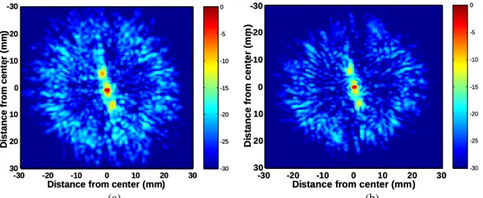
Two different focusing techniques have then been experimentally tested: spherical laws (no correction) and time reversal (Fink 1997, Fink et al 2003). Without any correction, the pressure field in the focal plane is affected by both inhomogeneous attenuation and phase distortion and three main effects are observed in figure 6: a mean 2 mm shift of the main lobe, a mean 1.25 mm spreading in the half width of the main lobe and up to 20 dB increase in the secondary lobe level. The wave front is thus slightly distorted when crossing the chest wall but is not dramatically defocused so that by increasing the total energy emitted by the array, it is possible to induce thermal ablation of the liver through the ribs (Wu et al 2004a, b, Kennedy et al 2004, Li et al 2007) without any correction.
-30 -25 -20 -15 -10 -5 0
Distance from center (mm)
D is ta n c e f ro m c e n te r (m m ) -30 -20 -10 0 10 20 30 -30 -20 -10 0 10 20 30 -30 -25 -20 -15 -10 -5 0
Distance from center (mm)
D is ta n c e f ro m c e n te r (m m ) -30 -20 -10 0 10 20 30 -30 -20 -10 0 10 20 30 -30 -25 -20 -15 -10 -5 0
Distance from center (mm)
D is ta n c e fr o m c e n te r (m m ) -30 -20 -10 0 10 20 30 -30 -20 -10 0 10 20 30 -30 -25 -20 -15 -10 -5 0
Distance from center (mm)
D is ta n c e fr o m c e n te r (m m ) -30 -20 -10 0 10 20 30 -30 -20 -10 0 10 20 30 (a) (b)
Figure 6: Two dimensional pressure field measured in the focal plane (dB scale): no correction (a) and time reversal (b).
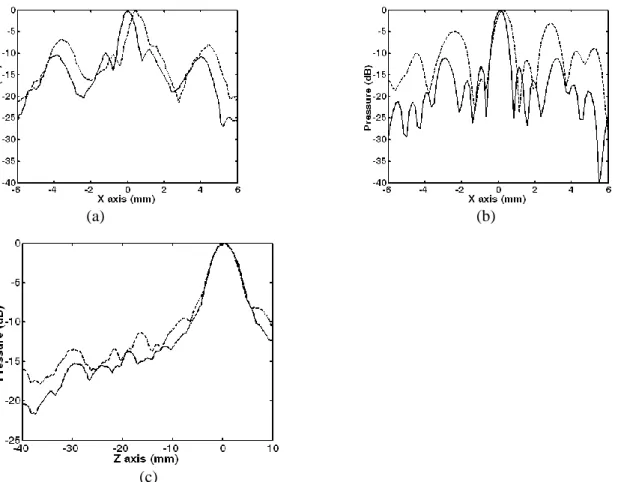
Then a time reversal experiment was conducted though the ribs: the wave front presented in figure 4a was time reversed and reemitted by the array. The pressure field was scanned by the hydrophone in the focal plane. Compared to the non-corrected beam, the position and the half width of the main lobe could be restored, as seen in figure 6. A cut of this 2D pressure distribution is plotted in the horizontal axis (X axis) in Figure 7a.
(a) (b)
(c)
Figure 7: Pressure distribution (dB scale) obtained with time reversal (gray line) and with no correction (dotted line) in the focal plane (a: experiment and b: simulation) and along the beam axis (c: experiment). These results show that time reversal is improving the focusing quality (1.73dB 1.26 dB) while slightly improving the pressure at the focal spot (Table 2). But the focusing quality is not the main concern when focusing though the rib cage: one also has to pay attention to the pressure level on the ribs that may cause a temperature elevation due to the high absorption of the bones and to induced side effects (Wu et al 2004a, b, Kennedy et al 2004, Li et al 2007).
Non-corrected Time-reversal Ratio
Experiments 6.75 7.03 1.04
3.2 Temperature measurements
Temperature elevation has been measured on several locations over the outer rib surface at the bone location for 5s sonications performed with each focusing technique (1600W.cm-2 at focus in water without the ribs). The maximum emission amplitude was the same for all the experiments and a thermal lesion was obtained at the focus in ex vivo tissue samples. The pressure at the focus was approximatively the same for the time reversal experiment and the non corrected experiment (Table 2). A summary of the mean temperature elevation is given on Table 3.
Focusing technique Mean elevation Standard deviation Maximum temperature elevation
No correction 5.9°C 2.2°C 9.1°C
Time Reversal (TR) 0.3°C 0.1°C 0.4°C
Table 3: temperature elevation on the ribs
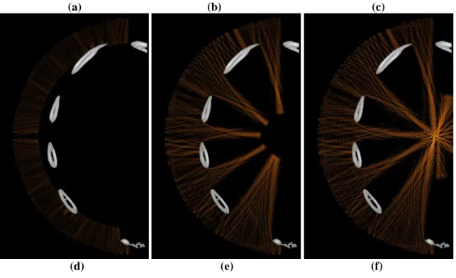
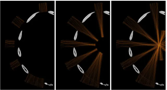
Figure 8 highlights the difference between both focusing techniques: snapshots of the propagation during treatment (continuous waves) are displayed without correction and with time reversal. Pressure fields are displayed in a dB scale. Pressure levels 40dB below the maximum pressure amplitude appear in black. The maximum pressure amplitude is the one obtained at the focus.
(a) (b) (c)
Figure 8: snapshots of the propagation during treatment: (a) (b) and (c) without correction and (d) (e) and (f) with time reversal (dB scale).
4. Discussion
Time reversal has been shown to be well suited for ribs sparing in liver treatment planning as it both improves the focusing quality and decreases the overheating of the ribs. Mathematically, it is the best adaptive technique to spare the ribs as it acts as a matched filter and maximises the ratio between the energy deposited at the target location and the total amount of energy emitted by the therapeutic array as demonstrated by Tanter et al (2000). Nevertheless, such a technique is invasive as it requires an acoustic source (or receiver) at focus. For clinical applications a non invasive approach would be needed. This should be feasible by using the therapeutic array in the receive mode in order to image the chest and localize ribs surface with the therapeutic array.
The ability of the array to image the ribs has been first validated on simulations. 29 transducers of 8mm in active diameter mounted on a spherical surface have been modelled. Pulse echo imaging sequences have been simulated with a reception beamforming and the corresponding image is displayed in figure 9a. It agrees with the original ribs geometry displayed in figure 9b.
Figure 9: (a) pulse echo imaging sequence simulated with a 2D finite differences code (b) ribs configuration.
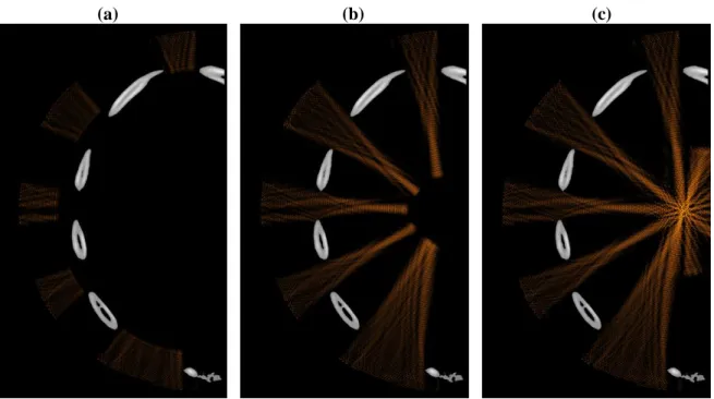
Transducers located in front of a rib bone can be identified. Instead of emitting a spherical wave (no correction) with the same phase and the same amplitude on each element of the array, one can thus set the amplitude to zero on the transducers located in front of the ribs. This has been done numerically and the result can be seen in figure 10: using this approach the ribs are not sonicated. However the energy ratio Er
(eq. 5) is 13% lower than by using time reversal. Indeed time reversal also benefits from diffraction effects on the edge of the ribs. One can see on figure 9 that without any correction, reverberations occur between the costal walls and the transducer without contributing to energy deposition at the focus. On the contrary time reversal largely sonicates between the ribs: it is much more efficient in terms of energy saving and also in decreasing temperature elevation on the ribs.
(a) (b) (c)
Figure 10: snapshots of the propagation during treatment: (a) (b) and (c) using a binarised spherical wave
In order to optimize the energy ratio Er (eq. 4), it would also be possible to reproduce a time reversal
operation instead of simply switching off some transducers: the propagation of a signal originated at the target location can be simulated with our numerical finite differences code in this simple model made of ovoid bones embedded in soft tissues. In that case, the location and size of each rib would be roughly provided by the echographic images (as the one presented in fig. 9a). This yields to non-invasive time reversal as the propagation from a virtual source located at the target position on the model is now computed instead of being measured experimentally as was the case in paragraph 3.1. This means that a stripped transducer might be an ingenious way to limit the overheating of the ribs (Civale et al 2006) but is not the optimal configuration.
It has been shown that time reversal acts as a spatial and temporal matched filter (Tanter et al 2000, Tanter et al 2001, Aubry et al 2001). In other words, for a given acoustic energy emitted by the array, it optimizes the acoustic energy deposition at the focus. This property holds even if the medium is absorbing, so that the following energy ratio between the energy deposited at the target location and the total amount of energy emitted by the therapeutic array is always optimized when using time reversal:
R
acoustical energy at focus E
total em itted energy by therapeutic array
(eq. 4)
In the case of the ribs, this energy ratio has been measured to be 36 times higher with time reversal than without correction.
Indeed time reversal naturally sonicates between the ribs in order to spare energy:
- if a rib bone is placed between the hydrophone and a transducer, the wave front is strongly absorbed during the first step of the time reversal process, and the amplitude recorded on this transducer is small so that the time reversed signal will also have a low amplitude. In the way back to the target point, this part of the way front will cross a second time the absorbing area but as its amplitude is low it will induce a low temperature elevation.
Time reversal is thus expected to minimize the temperature elevation on the rib surface. This is confirmed by the temperature measurements: a mean 0.3°C has been measured on the rib surface by using time reversal compared to more than 5°C without any correction as can be seen in table 3.
Another approach would consist in placing a set of virtual sources in the intercostals space in order to force the beam to go through these sources without sonicating on the ribs. Botros et al (1997, 1998) proposed to use so called “hybrid virtual arrays” made of such sources. To do so, they propose to solve optimal synthesis of complex pressure in the virtual array plane while minimizing power deposition at critical points. The pseudo inversion is based on a weighting in order to favour either the sparing of the ribs or the focusing quality at focus. It would be up to the physician to play with the weighting in order to plan the treatment. As time reversal is a matched filter, by favouring the sparing of the ribs the hydrid virtual array method would end up with the solution of time reversal focusing presented in this paper, but if the physician is willing to increase even more the temperature rise at focus, he could use the hybrid method, with the risk of slightly increasing the temperature elevation on the ribs.
5. Conclusion
Time reversal seems to be the most suited technique investigated in this paper in order to focus through the rib cage for therapeutic applications. The focusing quality is indeed well restored while the temperature elevation on the rib surface is negligible (a mean 0.3°C). The temperature elevation on the surface of the ribs can also be non invasively reduced by turning off the transducers that are located in front of rib bones. As shown in this paper, the imaging capabilities of the multi-element phased array technology enable to image the outer ribs surface. The locations of the bones appear clearly. This process is currently implemented for clinical investigations using 200 emitting and receive electronic channels. Another extension of this work would be to couple this adaptive focusing technique to 3D real-time motion correction techniques in order to take into account the relatively large respiratory motion during treatment (Pernot et al 2004). The ability of transmit/receive HIFU arrays to solve transribs propagation and motion correction, the two main problems of liver treatments clearly emphasize the potential of such dual-mode arrays.
6. References
Aubry JF, Tanter M, Gerber J, Thomas JL, Fink M 2001 Optimal focusing by spatio-temporal inverse filter : Part II Experiments Journal of the Acoustical Society of America 101 48-58
Aubry JF, Tanter M, Pernot M, Thomas JL, Fink M 2003 Experimental demonstration of noninvasive transskull adaptative focusing based on prior computed tomography scan Journal of the Acoustical Society of America 113(1) 84-93
Botros YY, Ebbini ES, Volakis JL 1998 Two-step hybrid virtual array-ray (VAR) technique for focusing through the rib cage IEEE Trans Ultrason Ferroelect Freq Contr 45 989–99
Botros YY, Volakis JL, VanBaren P, Ebbini ES 1997 A hybrid computational model for ultrasound phased-array heating in presence of strongly scattering obstacles IEEE Trans Biomed Eng 44 1039–50 Daum DR, Buchanan MT, Fjield T, Hynynen K 1998 Design and evaluation of a feedback based phased array system for ultrasound surgery IEEE Trans Ultrason Ferroelectr Freq Contr 45 43–8
Catane R, Beck A, Inbar Y, Rabin T, Sabshin N, Hengst S, Pfeffer RM, Hanannel A, Dogadkin O, Liberman B and Kopelman D 2007 MR guided focused ultrasound surgery (MRgFUS) for the palliation of pain in patients with bone metastases - preliminary clinical experience Annals of Oncology 18(1) 163-7 Chan AH, Fujimoto VY, Moore DE, Martin RW, Vaezy S 2002 An image-guided high intensity focused ultrasound device for uterine fibroids treatment Med. Phys. 29 2611–20
Chapelon JY, Cathignol D, Cain C, Ebbini E, Kluiwstra JU, Sapozhikov O, Fleury G, Berriet R, Chupin L, Guey JL 2000 New Piezoelectric Transducers for Therapeutic Ultrasound Ultrasound in Med. & Biol. 26(1) 153-9
Civale J, Clarke R, Rivens I, ter Haar G 2006 The use of a segmented transducer for rib sparing in HIFU treatments Ultrasound in Medicine & Biology 32(11) 1753-61
Daum DR, Smith NB, King R, Hynynen K 1999 In vivo demonstration of noninvasive thermal surgery of the liver and kidney using an ultrasonic phased array Ultrasound in Med. & Biol. 25(7) 1087–98
Ebbini ES, Yao H, Shrestha A 2006 Dual-mode ultrasound phased arrays for image-guided surgery Ultrasonic Imaging 28(2) 65-82
Fink M 1997 Time reversed Acoustics Physics Today 20 34-40
Fink M, Montaldo G, Tanter M 2003 Time reversal acoustics in biomedical engineering Annual Review of Biomedical Engineering 5 465-497
Furusawa H, Namba K, Nakahara H, Tanaka C, Yasuda Y, Hirabara E, Imahariyama M and Komaki K 2007 The Evolving Non-Surgical Ablation of Breast Cancer: MR Guided Focused Ultrasound (MRgFUS) Breast Cancer14(1) 55-8
Gelet A, Chapelon JY, Margonari J, Theilliere Y, Gorry F, Souchon R 1993 High-intensity focused ultrasound experimentation on human benign prostatic hypertrophy Eur Urol 23 44–7
Gelet A, Chapelon JY, Bouvier R, Souchon R, Pangaud C, Abdelrahim AF, Cathignol D, Dubernard JM 1996 Treatment of prostate cancer with transrectal focused ultrasound: Early clinical experience Eur. Urol. 29 174–83
Gianfelice D, Abdesslem K, Boulanger Y, Amara M, and Belblidia A 2003 MR Imaging-guided Focused Ultrasound Surgery of Breast Cancer: Correlation Between Dynamic Contrast-Enhanced MRI and Histopathologic Findings Breast Cancer Research and Treatment 82 93-101
Goss SA, Frizzell LA, Dunn F 1979 Ultrasonic absorption and attenuation in mammalian tissues Ultrasound Med Biol 5(2) 181-6
Goss SA, Johnston RL, Dunn F 1980 Comprehensive compilation of empirical ultrasonic properties of mammalian tissues II Journal of Acoustical Society of America 68(1) 93-108
Kennedy JE, Clarke RL, ter Haar GR 2002 The effects of absorbers such as ribs in the HIFU Beam-path on the focal profile 2nd Intl. Symp. on Therapeutic Ultrasound 185-92
Kennedy JE, Wu F, ter Haar GR 2004 High-intensity focused ultrasound for the treatment of liver tumours Ultrasonics 42 931–5
Kopelman D, Inbar Y, Hananel A, Freundlich D, Castel D, Perel A, Greenfeld A, Salamon T, Sareli M, Valeanu A, Papa M 2006 Magnetic Resonance-guided Focused Ultrasound Surgery (MRgFUS): Ablation of Liver Tissue in a Porcine Model Eur Journal of Radiology 2006 59 157-62
Li JJ, Xu GL, Gu MF 2007 Complications of high intensity focused ultrasound in patients with recurrent and metastatic abdominal tumors World Journal of Gastroenterology 13 (19) 2747-51
McGough RJ, Kessler ML, Ebbini ES, Cain CA 1996 Treatment planning for hyperthermia with ultrasound phased arrays IEEE Trans Ultrason Ferroelectr Freq Contr 43 1074–84
Madersbacher S, Kratzik C, Susani M, Marberger M 1961 Tissue ablation in benign prostatic hyperplasia with high intensity focused ultrasound J Urol 152 1956–61
Madersbacher S, Pedevilla M, Vingers L, Susani M, Marberger M 1995 Effect of high intensity focused ultrasound on human prostate cancer in-vivo Cancer Res 55 3346–51
Mehta SS, Antich PP 1997 Measurement of Shear-Wave Velocity by Ultrasound Critical-Angle Reflectometry (UCR) Ultrasound in Medicine and Biology 23(7) 1123-26
Okada A, Murakami T, Mikami K, Onishi H, Tanigawa N, Marukawa T, Nakamura H 2006 A Case of Hepatocellular Carcinoma Treated by MR-guided Focused Ultrasound Ablation with Respiratory Gating Magn Reson Med Sci 5(3) 167-71
Pernot M, Aubry JF, Tanter M, Thomas JL, Fink M 2003 High power transcranial beam steering for ultrasonic brain therapy Physics in Medicine and Biology 48 (16) 2577-89
Pernot M, Tanter M, Fink M 2004 3D real time motion correction in High Intensity Focused Ultrasound therapy Ultras. Medic. Biol. 30(9) 1239-49
Sanghvi NT, Fry FJ, Bihrle R, Foster RS, Phillips MH, Syrus, J, Zaitsev AV, Hennige CW 1996 Noninvasive surgery of prostate tissue by high-intensity focused ultrasound IEEE Trans Ultrason Ferr 43 1099–110
Silverman RH, Vogelsang B, Rondeau MJ, Coleman DJ 1991 Therapeutic ultrasound for the treatment of glaucoma Am J Ophthalmol 111 327–37
Stewart EA, Gedroyc WMW, Tempany CM, Quade KM, Inbar Y, Ehrenstein T, Shushan A, Hindley JT, Goldin RD, David M, Sklair M, Rabinovici J 2003 Focused ultrasound treatment of uterine fibroid tumors: Safety and, feasibility of a non-invasive thermoablative technique Am. J. Obstet. Gynecol. 189 48–54
Tanter M, Aubry JF, Gerber J, Thomas JL, Fink M 2001 Optimal focusing by spatio-temporal inverse filter : Part I. Basic principles Journal of the Acoustical Society of America 101 37-47
Tanter M, Pernot M, Aubry JF, Montaldo G, Marquet F, Fink M 2007 Compensating for bone interfaces and Respiratory motion in High Instensity Focused Ultrasound Journal of Hyperthermia 23(2) 141-51 Tempany CMC, Stewart EA, McDannold N, Quade BJ, Jolesz FA, Hynynen K 2003 MR imaging-guided focused ultrasound surgery of uterine leiomyomas: A feasibility study Radiology 226 897-05
Vallancien G, Harouni M, Veillon B 1992 Focused extracorporeal pyrotherapy: Feasibility study in man Jour Endourol 6 173–80
Vimeux F, De Zwart J, Palussiere J, Fawaz R, Delalande C, Canioni P, Grenier N, Moonen C 1999 Real-Time Control of Focused Ultrasound Heating Based on Rapid MR Thermometry Investigative Radiology 34(3) 190-3
Williams JL Ultrasonic wave propagation in cancellous and cortical bone: Prediction of experimental results by Biot’s theory Journal of Acoustical Society of America 91 1106-12
Wu F, Wang ZB, Chen WZ 2004 Extracorporeal high intensity focused ultrasound ablation in the treatment of 1038 patients with solid carcinomas in China: an overview Ultrasonics Sonochemistry 11(3-4) 149-54
Wu F, Zhi-Biao W, Wen-Zhi C, Hui Z, Jin B, Jian-Zhong Z, Ke-Quan L, Cheng-Bing J, Fang-Lin X, Hai-Bing S 2004 Extracorporeal High Intensity Focused Ultrasound Ablation in the Treatment of Patients with Large Hepatocellular Carcinoma Annals of Surgical Oncology 11 1061-9