HAL Id: hal-01455510
https://hal.inria.fr/hal-01455510
Submitted on 13 Jul 2017
HAL is a multi-disciplinary open access
archive for the deposit and dissemination of
sci-entific research documents, whether they are
pub-lished or not. The documents may come from
teaching and research institutions in France or
L’archive ouverte pluridisciplinaire HAL, est
destinée au dépôt et à la diffusion de documents
scientifiques de niveau recherche, publiés ou non,
émanant des établissements d’enseignement et de
recherche français ou étrangers, des laboratoires
HOBIT: Hybrid Optical Bench for Innovative Teaching
David Furio, Stéphanie Fleck, Bruno Bousquet, Jean-Paul Guillet, Lionel
Canioni, Martin Hachet
To cite this version:
David Furio, Stéphanie Fleck, Bruno Bousquet, Jean-Paul Guillet, Lionel Canioni, et al.. HOBIT:
Hybrid Optical Bench for Innovative Teaching. CHI’17 - Proceedings of the 2017 CHI Conference on
Human Factors in Computing Systems, May 2017, Denver, United States. �10.1145/3025453.3025789�.
�hal-01455510�
HOBIT: Hybrid Optical Bench for Innovative Teaching
David Furi´o
Universit´e de Bordeaux
[email protected]St´ephanie Fleck
Universit´e de Lorraine
[email protected]Bruno Bousquet
Universit´e de Bordeaux
[email protected]Jean-Paul Guillet
Universit´e de Bordeaux
[email protected]Lionel Canioni
Universit´e de Bordeaux
[email protected]Martin Hachet
Inria
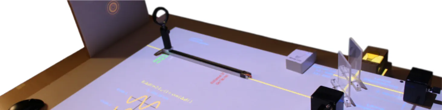
[email protected]Figure 1. Simulation and augmentation of a Michelson interferometer experiment. Physical and digital content are merged in a unique environment.
ABSTRACT
Practical work in optics allows supporting the construction of knowledge, in particular when the concept to be learned remains diffuse. To overcome the limitations of the current experimental setups, we have designed a hybrid system that combines physical interaction and numerical simulation. This system relies on 3D-printed replicas of optical elements, which are augmented with pedagogical information. In this paper, we focus on the well-known Michelson interferometer experiment, widely studied in undergraduate programs of Science. A 3-months user study with 101 students and 6 teachers showed that, beyond the practical aspects offered by this system, such an approach enhances the technical and scientific learning compared to a standard Michelson interferometer experiment. ACM Classification Keywords
H.5.2. Information Interfaces and Presentation (e.g., HCI): User Interfaces; K.3.1. Computers and Education: Computer Uses in Education
Author Keywords
Education and Training; Optics; Augmented Reality; Simulation; Michelson interferometer
Permission to make digital or hard copies of all or part of this work for personal or classroom use is granted without fee provided that copies are not made or distributed for profit or commercial advantage and that copies bear this notice and the full citation on the first page. Copyrights for components of this work owned by others than the author(s)must be honored. Abstracting with credit is permitted. To copy otherwise, or republish, to post on servers or to redistribute to lists, requires prior specific permission and/or a fee. Request permissions from [email protected].
CHI 2017, May 06-11, 2017, Denver, CO, USA
Copyright © 2017 ACM ISBN 978-1-4503-4655-9/17/05 ¨O$15.00. DOI: http://dx.doi.org/10.1145/3025453.3025789
INTRODUCTION
In optics, many concepts and phenomena are difficult to per-ceive and understand. This is particularly true with wave optics where phenomena may appear as counterintuitive [14]. Hence, universities and schools generally reinforce theoretical courses with physical experiments where students manipulate the con-cepts to be learned. The integration of laboratory activities into the classroom is an essential part of science education [19] since it allows students to observe, test hypotheses, and apply their understanding of the physical world [2, 16]. Further-more, the observation, testing and experimentation found in experimental physics have a positive impact on the students’ motivation [25, 26].
However, current experimental setups suffer from several limi-tations, as reported by the optics teachers with whom we have worked (see Evaluation section). First, from a practical point of view, setting up and maintaining optics experiments may be time consuming (in particular in the case of wave optics). The required material is generally expensive and fragile. This limits the number of experiments that can be run. Experi-ments can be dangerous too, in particular as soon as laser sources are used. These observations were also reported in the literature [15, 22, 4].
Second, from a pedagogical point of view, the teachers as well as other prior work [27] reported that traditional experiments were not always sufficient for transmitting knowledge. Stu-dents often have difficulties to develop an understanding of the complexity and ambiguity of empirical work. They may also fail to acquire the skills needed to calibrate and troubleshoot
setups used to make observations, whereas this learning is the main objective of practical works [17].
All these issues prompt to upgrade traditional optics experi-ments by i) overcoming the practical limitations of the current experimental setups and ii) providing pedagogical supports aiming to help the understanding of the studied phenomena. To this end, we propose HOBIT, an interactive system which stands for Hybrid Optical Bench for Innovative Teaching. Our goal is to let students operate as if they were working with a real optics experiment, but where the observed phenomenon comes from a numerical simulation. Beyond the simulation, this system allows augmenting the experiment with co-located pedagogical supports (see Figure 1).
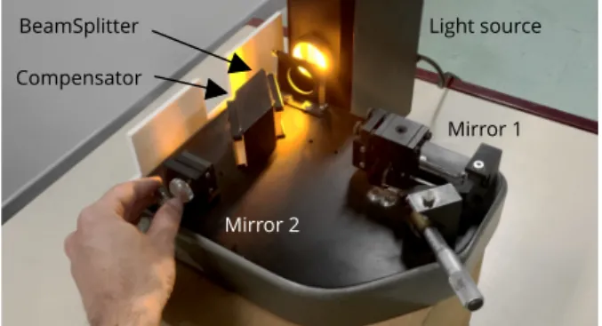
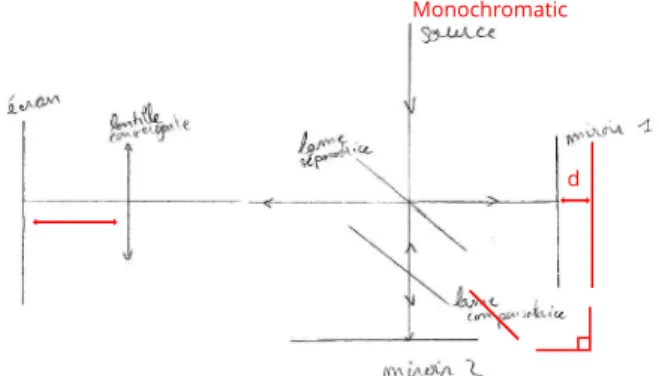
In a first step, we focused on the Michelson interferometer, which is used in numerous applications (e.g. Fourier Trans-form Spectroscopy, Laser Interferometer Gravitational-Wave Observatory, and so on). Consequently, the Michelson in-terferometer (Figure 2) is one of the most popular optics ex-periments. It is based upon the division of a light wave into two beams that reflects on two separate plane mirrors before merging back into a combined beam whose projection can be observed on a projection screen. By slightly modifying the axial position or the orientation of the mirrors, one can observe resulting interference patterns—fringes or rings—on the screen (See Figure 5(a)). Various experiments can be performed with a Michelson interferometer, such as the mea-surement of wavelengths (e.g. Helium-Neon Laser), precise distance, or refractive indexes of transparent materials. There-fore, it is fundamental that, during lab work sessions, students familiarize themselves with the setup adjustments. They also need to translate their theoretical background into practice and understand causal effects of their direct manipulations on optical interferences phenomena.
Our contributions for this work are
• the design of a new interactive system that simulates and augments a Michelson interferometer
• a study that assesses the pedagogical relevance of the pro-posed approach in an ecological situation.
Mirror 1 BeamSplitter
Compensator
Light source
Mirror 2
Figure 2. A picture of a standard Michelson interferometer where a user is moving the orientation of one of the mirrors. The interference pattern is projected on a screen located on the left of the interferometer (not visible in this image).
RELATED WORK
Due to the abstract nature of the studied concepts, optics is one of the fields where many works were conducted to improve educational approaches and tools. Many authors emphasize the importance of Hands-on learning experience, as we do in our approach. This is notably the case of the workshop carried out by Takayama et al. [24]. During two hours, basic optics concepts (e.g. polarization and wavelength) were introduced to high school students who performed the experiments themselves, guided by two experts. Despite direct manipulations, such traditional experiments may suffer from a disconnection between the theoretical concepts to learn and the actual handling, since students can not observe the phenomena and the underlying theoretical concepts at the same time. Beyond standard experiments, authors have explored alter-native technologies to improve the teaching of physics (and optics) concepts. For example, Rodrigues and Carvalho [20] developed video-based experimental activities. Real exper-iments were recorded and students had to answer questions by watching and analyzing the videos. Such multimedia sys-tems have interesting advantages over traditional experiments. Beyond cost and safety considerations, videos can be freely distributed on the web, making possible to spread them to a large number of students that can work with them at any time, and as many times they want. On the other hand, physical in-vestigations are not possible with such intangible approaches. This can maintain misconceptions [29]. To overcome this, our work supports physical interaction.
In past few years, new approaches based on Virtual Reality (VR) have emerged with the popularization of the related tech-nologies. These approaches rely on the immersion of users in an interactive virtual environment. Related with optics educa-tion, Hayes et al. [11] developed a VR educational module that implements a virtual laboratory with realistic models of optical devices. In this virtual lab, students can set up and perform an optical experiment, e.g. dealing with laser diode characteris-tics and fiber coupling. The module was composed of three levels with a short quiz at the end of each one to measure the student’s understanding of the subject. Such VR environments are very flexible, and numerous experiments, which could be potentially dangerous or expensive in reality, can be built. On the other hand, pure VR approaches suffer from limitations. In particular, when equipped with a Head-Mounted-Display, the student is isolated in a virtual world, and the communication with other students and teachers is harder. This contradicts pedagogical principles that emphasis the importance of social interaction in learning [12, 5]. Moreover, the way the student manipulates virtual optics components is very far from what she or he would do during a real experiment. Consequently, the transition from the virtual to the real environment might be a problem. At the opposite, with HOBIT, students and teachers interact around a tangible experiment that is very close to the true experiment.
Related to VR, Augmented Reality (AR) has grown in impor-tance in the last years. By superimposing virtual elements to real ones, AR allows enriching the real world with additional information. In education, this can help students to understand
abstract concepts that may not be visible in real life (e.g. [8, 23]). With regard to optics education, a few AR experiments have been carried out. Yamaguchi and Yoshikawa [32] devel-oped a system for the construction of an optical holography setup. The virtual optics components (e.g. lenses, and mirrors) were displayed on a screen on top of filmed markers. The students had to build an optical holography experiment by ma-nipulating the markers in front of a camera. Compared to this approach where the augmentation is observed through a screen, with HOBIT, virtual information is directly projected onto the physical environment, using Spatial Augmented Reality [1]. Some authors like Underkoffler and Ishii [28], or Falc˜ao and Price [9] had followed an approach similar to ours where projection is used to combine real and virtual information within a same physical space. Underkoffler and Ishii system aimed at simulating the interaction of laser light with various optical components in holographic setups. A projector situ-ated above a table allows displaying augmented information (light path) around physical objects that are tracked thanks to a video/markers system. Similarly, the system of Falc˜ao and Price consisted in an interactive tabletop environment for simulating some basic optics phenomena and was targeted at children. A projector situated on top of the table displayed the augmented information and the different physical objects were tracked from below the table thanks to a video/markers system. Continuing with AR, Yoon and Wang [33] developed a system to observe and manipulate magnetic fileds in real-time. A camera placed above the working area tracked the magnets and the augmented information (magnetic fields) was displayed on a screen situated in front of the user. These sys-tems reproduce conceptual and simplified optics or magnetics experiments. In our case, with HOBIT, our goal is to mimic as much as possible true experiments, and to augment them with pedagogical supports.
Another interesting project related to HOBIT is TinkerLamp, developed by Do-Lenh et al. [7]. TinkerLamp tries to help logistics students learn the theoretical concepts through exper-imentation and AR in a scaled-down model of a warehouse. It is composed of an interactive tabletop, a projector and a camera placed above the tabletop, and a series of physical ele-ments (sheets, models, cards, etc.) that can be tracked thanks to markers. HOBIT shares some of the ideas presented in TinkerLamp and some of the aforementioned projects. This no-tably includes tabletop configurations, top projectors, tangible interaction, and control cards.
Despite the effort that has been put to build these new edu-cational tools, few studies have been conducted to assess the learning outcomes. Underkoffler and Ishii [28] performed a qualitative user study with 8 students. This study notably showed that the students were pleased with the fast prototyping capabilities provided by the system, but no learning outcomes were studied. In their study, Hayes et al. [11] showed that the VR module they proposed improved significantly the initial knowledge of the targeted pedagogical content. On the other hand, no comparison with a baseline condition was performed. The studies of Falc˜ao and Price [9], and Yoon and Wang [33] were focused on children and the main goals focused on
study-ing the collaboration between them. The results showed that AR and tangible interaction increased the teamwork of the children, but no learning outcomes were studied. Do-Lenh et al. [7] carried out a study to evaluate the learning outcomes of TinkerLamp. The authors suggest that TinkerLamp improved the learning outcomes compared to the other conditions. In this paper, beyond describing the HOBIT platform, we report an experiment whose goal is to explore how a hybrid system as the one we propose impacts the building of new knowledge and skills. To this end, we conducted a study with a large number of participants (N = 101), and we com-pared HOBIT to a standard Michelson interferometer (see section Evaluation).
TECHNICAL DESCRIPTION System Overview
HOBIT is an interactive platform dedicated to the simula-tion and the augmentasimula-tion of optics experiments. The main components of the system are:
• A set of optical replicas whose goals is to mimic true optical elements (e.g. lenses and mirrors mounted on mechanical holders).
• A numerical simulation that computes in real-time inter-ference patterns from a physical model, and for which the result is projected on a screen.
• An augmentation of the board by way of a second projector located on top of the experiment.
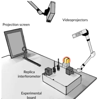
Users modify the parameters of the simulation by manipulating the optical replicas. As they would do with a real experiment, they can observe the result of their action on the projection screen. The augmentation aims at co-locating additional infor-mation within the physical experiment. Figure 3 illustrates the
Experimental board Projec5on screen Replica interferometer Videoprojectors
HOBIT platform in a configuration that reproduces a Michel-son interferometer.
The total cost of the components required to build the plat-form (laptop, videoprojectors, and sensors) is about four times cheaper than a standard Michelson interferometer, and sev-eral experiments can be built from the same platform. With HOBIT, the experiment is much faster to set up than with traditional optics experiments. Moreover, because the light sources are not real, HOBIT prevents from safety issues, in particular in the case of laser sources.
Optical replicas
Optical replicas are 3D printed objects equipped with elec-tronic sensors. For the Michelson interferometer, we built the following components.
2 light sources (low-pressure sodium lamp and white LED) are plastic boxes with RFID tags. A stand equipped with a RFID reader allows detecting which light source is experi-mented.
2 mirror holders are equipped with knobs that mimic micro-metric screws, which are used to control the position and orientation of mirrors in real experiments. One of them (mir-ror 1, see Figure 4) is equipped with one knob dedicated to control the axial translation of the (virtual) mirror. The other one (Mirror 2) is equipped with two knobs dedicated to the orientation of the mirror. It is worth noticing that translation and orientation changes on mirrors in reality are not perceptible. Hence, replicas appear as true mirror hold-ers in the simulator. The resolution of the knobs is adjusted to mimic those installed in the real setup. In particular, for the axial translation, 1 full turn of the knob was set to induce a 500 µm translation. The same happens with the knobs of the Mirror 2 where one full turn of the knob is mapped to 1°.
1 movable lens mounted on a linear potentiometer allows simulating the modification of the lens-to-screen distance. One step of this sensor corresponds approximately to 0.29 cm.
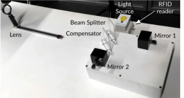
2 passive elements mimic the role of the beam splitter and the compensator. Mirror 2 Mirror 1 Lens Compensator Beam Spli4er RFID reader Light Source
Figure 4. The optical replicas in a Michelson interferometer setup. The Arduino board is embedded under the platform on which the mirrors, beam splitter and compensator are fixed.
Figure 4 illustrates the optical replicas we build for the Michel-son interferometer.
The RFID reader as well as all the sensors are connected to an Arduino board located under the platform where the mirrors, beam splitter and compensator are fixed. This board detects all the changes in the sensors states and sends them to the computer via an USB connection. The data is transmitted every 50ms.
Numerical simulation
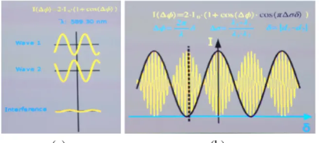
The numerical simulation computes the interference pattern from the characteristics of the light source and the position and orientation of the mirrors and lens. The intensity of a point on the screen is computed based on the theory of interference involving two waves. The detailed model that is used to com-pute the interference patterns is described in the accompanying complementary file for reproducibility purposes.
At the end, the obtained interference patterns are very close to the ones that are obtained from a true Michelson interferome-ter, as depicted in Figure 5.
(a) (b) (c)
Figure 5. Examples of ring interference patterns of the low pressure sodium lamp from (a) a standard Michelson interferometer and from (b) the numerical simulation of HOBIT. (c) White light fringes interference pattern obtained with HOBIT.
Augmentation
The augmentation consists in projecting pedagogical informa-tion into the experiment. This informainforma-tion (e.g. texts, draw-ings, and animations) have been designed to support the dents’ needs. For example, with a standard Michelson, stu-dents may often be lost because they have no idea of what is happening when manipulating a mirror. Have they turned too much the screw? Or not enough? At the end, they may observe nothing without knowing why. With HOBIT, a schematic rep-resentation of the current state of the optical elements can be displayed next to them, as illustrated in Figure 6(a). This may help students to understand how their actions impact the observed phenomenon. Such an augmentation would not have been possible with a standard Michelson interferometer. In-deed, the precise state of the system needs to be known, which is not the case with a standard version.
Animations may also help students to understand how light propagates. To this end, we propose the option to launch an animation that highlights the light path, and that shows how the waves coming from the two mirrors superimpose together. This is illustrated in Figure 6(b).
(a) (b)
Figure 6. (a) Augmented information displayed next to the mirrors. The blue arrow indicates that Mirror 2 is being tilted forward, and the cur-rent angle is 002200. The drawing on the left gives an indication of the x
orientation of Mirror 2, and the graduated linear scale on top magnifies the current position of Mirror 1. (b) Light path and waves combination.
Similarly, advanced pedagogical supports can be displayed directly onto the experimental board. For example, Figure 7(a) and 7(b), illustrates two representations of the signal that could be measured at a specific point of the visualized interference pattern. This point can be selected by way of a mouse input. Such representations aims for helping students to understand how the two waves combine together and, consequently, why a resulting intensity is observed at the selected location. They also provide explanation on the changing contrast that is ob-served in the case of low-pressure sodium lamp, which spec-trum is characterized by two wavelengths very close one to the other. Formulas related with these phenomena can be dis-played, too (see Figure 6). The parameters of these formulas are updated in real-time according to the actions performed by the students. This may help the students to strengthen the link between the observed phenomena, various representa-tions, and the underlying concepts, all of them in a unique environment.
(a) (b)
Figure 7. Intensity of the interference pattern at a given location (a) and modulation of contrast (b) can be displayed close to the observed phenomena.
It is worth noting that all the augmentations and visual feed-back features can be activated on demand. They are toggled from a keypad that stands next to the experiment. This keypad is active only when the option card equipped with a RFID tag is in contact with a dedicated RFID reader. A start card can also be used to instantly put the system back to an initial state, which is not possible with a standard Michelson interferome-ter. These cards give the teacher control over the application and the different pedagogical supports. At any moment, the teacher can place one of the cards in the RFID reader to enable or disable the privileges the card gives. For example, students
are not able to run the simulation until the teacher has given them permission to do it by using the start card. The option card lets the teacher enable or disable the keypad in order to display or hide the augmented feedback. This notably gives the professor the ability to support his or her explanation of the theoretical concepts during the experiment. It also enables the teacher to control the difficulty of the experiment. Of course, the teacher can also decide to let the students manip-ulate the keypad by themselves, so they can experience, test, and discuss about the experiment.
EXAMPLE OF PRACTICAL WORK WITH HOBIT
After having switched on the computer and the two video-projectors, the teacher runs the application. It will remain in a “stand by” mode until the teacher uses the start card on the RFID. Then, she or he provides an exercise form to the group composed of, typically, two or three students. The stu-dents have to experiment with the system to answer this form. For example, they have to find the right configuration of the setup for obtaining interference fringes with a sodium lamp. First, they place the (fake) sodium light on the dedicated stand. Then, they can manipulate the optical elements in order to find the concrete configurations that were theoretically presented during the lecture courses. If students encounter difficulties, the teacher can decide to display additional information like the current state of the mirror (see Figure 6(a)) and the place where the lens should be positioned to ensure adequate imag-ing conditions. To do so, the teacher just needs to activate the keypad with the option card, and toggle the corresponding option by pressing the associated key. Once the students have managed to obtain the expected interference pattern, they can physically measure the period of the fringes to determine the angle value of the mirror, directly on the projection screen (see Figure 8(a)), as they would do with a real Michelson interferometer. After the students have modified the system in order to observe rings on the screen, the teacher wants now to explain the modulation of contrast that can be observed on the pattern. The teacher decides to display a new visual feedback to support her or his explanation (see Figure 8(b)). Finally, the students have to observe what happens with a white light. Students just need to swap the sodium light box with the white light box, and they can now continue experimenting. After the experiment finishes, the teacher uses the start card to reset the system and begin a new experiment with the predefined conditions.
(a) (b)
Figure 8. Example scenarios. (a) A student measures physically the pe-riod of the fringes on the projection screen. (b) Teacher explaining the modulation of contrast.
EVALUATION
We conducted a user study to evaluate HOBIT in a real ex-perimental class similar to the one described in the previous section. Our main objective was to explore how this system impacts scientific and technical learning compared to a stan-dard corresponding experiment. We also explored the user experience and attractiveness of the system.
Subjects and apparatus
A total of 101 students (82 males and 19 females; mean age: 19.16±0.82 years old) and 6 teachers (5 males and 1 female; mean seniority in teaching position: 18.2±6.2 years old) par-ticipated to the study. The students were second-year students of a University institute of technology in optics. The teachers (3 assistant professors, 2 associate professors and 1 university professor) were those in charge of the optics lab work training program. All the teachers were experienced with standard Michelson interferometer teaching. They were all motivated by teaching in practical sessions and confident in their pro-fessional skills. All of them declared a propro-fessional use of standard digital technologies (e.g. creation of their teaching contents or their presentation slides). On the other hand, they were novice with emerging technologies (e.g. augmented real-ity and virtual realreal-ity). Before the experiment, the 6 teachers were invited to participate to a presentation and regulation session of the study methods. In order to get familiar with HOBIT, they first experimented with the system, guided by the research team, and they completed the problem-solving task corresponding to the upcoming students lab works. This took approximately 1 hour. After this training time, the mean perception of their a priori capability to use HOBIT during a lab work session was 5.1±2.2 on a Likert scale in 7 levels. The study took place directly at the University of Bordeaux, during 3 months. Three conditions were tested:
• MI, a standard Michelson Interferometer
• SMI, a Simulator of a Michelson Interferometer, as de-scribed previously, but with no pedagogical augmentations. The SMI condition is thus a pure simulation of MI.
• ASMI, corresponding to the SMI condition, plus the peda-gogical augmentations.
Our hypotheses were that
H1: replacing a real experiment (MI) by a simulated one (SMI) does not decrease the learning performance H2: an augmented condition (ASMI) improves the learning
compared to non-augmented ones (MI and SMI),
H3: the students who have learned with HOBIT (SMI and ASMI conditions) are able to transfer their knowledge to a real condition (MI).
MI and [A]SMI were installed in two separate rooms of the training lab, with similar setups (comparable room size, similar tables and chairs, similar lighting conditions).
Experimental protocol
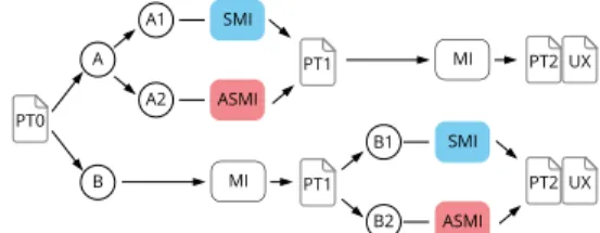
One month before the lab work sessions, all students answered a pre-test questionnaire PT0 (see description in the Results sec-tion). This allowed us to estimate their preliminary knowledge on Michelson interferometer after the lecture courses period. Then, the students were divided into four homogeneous groups (see Table 1). The training sessions were carried out in pairs and lasted four hours (two hours per condition). The members of group A1 and A2 used SMI (resp. ASMI) first, and then MI. The members of group B1 and B2 used first MI and then SMI (resp ASMI). Students from each group were assigned to each teacher in order to limit a “teacher effect” (see [18]). During the first two-hours session, students had to solve a set of problems involving interferometry technical skills and knowledges. After the session, the students filled out a post-test learning assessment (PT1), and they swapped with the group having done the other condition. During the second two-hours session, students had to solve similar problems as in the first session. At the end of the second session, they answered a new post-test learning assessment (PT2), and they filled out a user experience questionnaire (UX) including the french translation of the simplified Attrakdiff survey [13]. The questions we asked in this UX questionnaire were oriented towards pedagogical needs, i.e. referring on usability, useful-ness, and meaningfulness. Indeed, the personal perception of a pedagogical support could influence the learning quality, as it play a role in the extrinsic motivation of the user [21]. The pedagogical content, the training goals and the related exercises were prepared by the teachers team (see Table 2). A total of 95 students’ forms were analyzed (4 students did not fill the forms, and 2 of them provided non-exploitable documents). Figure 9 summarizes the whole protocol. It is worth noting that in each session teachers explained how to use the system, either [A]SMI or MI. They were also available to clarify any doubts the students had, as done in ordinary lab work conditions. In order not to introduce possible inequity be-tween the groups, no academic grade related to the Michelson interferometer was given.
A A1 A2 B B1 B2 SMI ASMI MI MI ASMI SMI PT0 PT1 PT1 PT2 PT2 UX UX
Figure 9. Summary of the protocol. A1, A2, B1, and B2 are the groups of students, PT0 refers to the pre-test, PT1 and PT2 to the post-tests, and UX to the user experience questionnaire. MI refers to the real Michelson interferometer; SMI refers to the Michelson interferometer simulator; and ASMI refers to the interferometer simulator with augmentation.
Groups A1 A2 B1 B2
Number of participants 19 27 22 27 Mean±SD age 19.00±0.75 19.04±0.81 18.95±0.90 19.46±0.71
Male/Female 13/6 21/6 20/2 22/5
Training goals Wave optics: Michelson interferometry Learning content Origin of interference fringes and rings
Role of the optical components
Influence of the light source (mono or polychro-matic)
Technical skills Mobilize precise adjustments
Identify and set up a technical configuration for various interference phenomena
Table 2. Pedagogical objectives of the lab work training program
Global reliability and design relevance
Overall, the subjects found that HOBIT worked well (mean and SD score on a 7 points Likert scale: 5.73±1.57; 7 be-ing “fully agree”). Durbe-ing their manipulations, the students declared that they were not disturbed by occlusion problems (1.74±1.14, 7 being “fully disturbed”) nor by problems of delay between their actions and the resulting system reaction (2.05±1.31). They globally felt that the operating mode of HOBIT (SMI and ASMI conditions) was close to a standard Michelson interferometer (5.09±1.48, 7 being “fully agree”). These declarative results tend to show that the physical prox-imity of HOBIT with a standard Michelson experiment is meaningful.
Results on learning
In order to estimate the pedagogical relevance of HOBIT, we assessed its effectiveness in regard to the achievement of the learning goals described in Table 2. This assessment fo-cused on the students capability to schematize and to explain scientifically an interferometer configuration and the related observable phenomena (e.g. Figure 2). In the pre-test (PT0), the students had to report how to obtain interference fringes with a monochromatic light source. In PT1, they had to ex-plain how to obtain interference rings with a monochromatic light source. Finally, in PT2, we assessed their ability to ex-plain how to obtain interference fringes, as in PT0, but with a polychromatic light source (see Figure 5(c)). Competency is effective for a learner when the integrated set of knowledges, skills and judgment enable her or him to effectively perform in various situations [3]. Slight variation between the tests ensures that the students have to think again about the correct answer. These tests allow us to estimate the impact of the condition (MI, SMI or ASMI) on the evolution of the learning and on its stabilization.
In addition to these tests, we also asked the students to an-swer a set of questions referring to general definitions and mathematical exercises about interferometry. These questions were asked after PT0, PT1, and PT2. They were related to previous courses (e.g. “definition of the parameters of an op-tics formula”) and the corresponding skills were not targeted during the lab sessions (See Table 2). The assessment of these questions showed no differences between the groups, for each test. This allows us to verify that the observed learning evo-lutions were due to the learning condition only, and not to a group effect. Indeed, practical work may reactivate previous knowledge, and re-introduce non homogeneity concerning the initial knowledge of the groups.
The answers to the tests and the diagrams produced by the students were scored by a teacher and a researcher of the project team, using a scale from 0 to 5. The teacher and the researcher first scored 50 tests in a double-blind approach, with harmonization steps after 10, 30 and 50 assessments to validate the scoring scale. Then, i) the researcher assessed all the remaining tests and ii) the teacher checked the results in order to validate the scoring. Less than 10 equivocal tests were discussed. This analysis of the type of answers enabled us to estimate the learning level for each student after each session. The score of 5 was given to diagrams that were fully correct and adequately annotated. In this case, the learning is considered as acquired. The score of 4 corresponds to correct but partial answers with small omissions or broad wording. The score of 3 corresponds to correct but partial answers with notable omissions (i.e., optical element, angle, etc.) and con-fused explanations (i.e., lack of scientific vocabulary). Both 4 and 3 scores were counted as an underway learning. Finally, the scores of 2, 1, and 0 were given in case of wrong answers (diagram without any of the expected elements and/or conflict-ing explanations), off-topics, or blank answers, respectively. This refers to not acquired knowledge. Figure 10 illustrates an example of diagram.
It is worth to mention that all the analyzes carried out for the learning data as well as the UX data use the Aligned Rank Transform for nonparametric factorial ANOVAs as described by Wobbrock et al. [30]. After the Aligned Rank Transform processes the data, ANOVA tests can be performed. One ad-vantage of using the Aligned Rank Transform with ANOVAs over common nonparametric tests is that we can analyze mul-tiple factors and their interactions.
Pre-test PT0
The scoring of PT0 showed that 94% of the students were not proficient in schematization and explanation of interferome-ter configuration before starting the lab work training session (mean score of the whole cohort: 2.52±1.21, see Table 3 and Figure 11). Most of their mistakes were linked to
inappropri-d
Mirror 1 and 2 have to be perpendicular and at different distances from the beam splitter.
The observed interference rings patterns depend on distance d. The screen has to be on the focal plane of the lens.
Monochromatic
Figure 10. Example of diagram produced by a student at PT1. She was asked to explain the configuration in which interference rings can be observed. This diagram has been marked as “under way”. Indeed, the overall structure is correct, but important information is missing (e.g. lack of the shift distance d).
ate positioning or omissions of optical components, lack of relevant annotations, or confusions with other configurations or with other interferometer (e.g. Young’s interferometer). It confirms previous studies indicating that university students do not easily understand the physical models and have many difficulties to construct mental images only with a theoretical approach (see e.g. [6]). A one-way ANOVA revealed no sig-nificant differences between the four groups (F[3, 87]=1.33, p=0.27, hG2=0.04; see also PT0 in Table 3).
Post-test PT1
A two-factor mixed ANOVA showed that after the first two-hours training sessions, the overall knowledge about the interferometer configurations has improved significantly (F[1,86]=61.94, p<0.01, hG2=0.26 / PT0: 2.48±1.21; PT1:
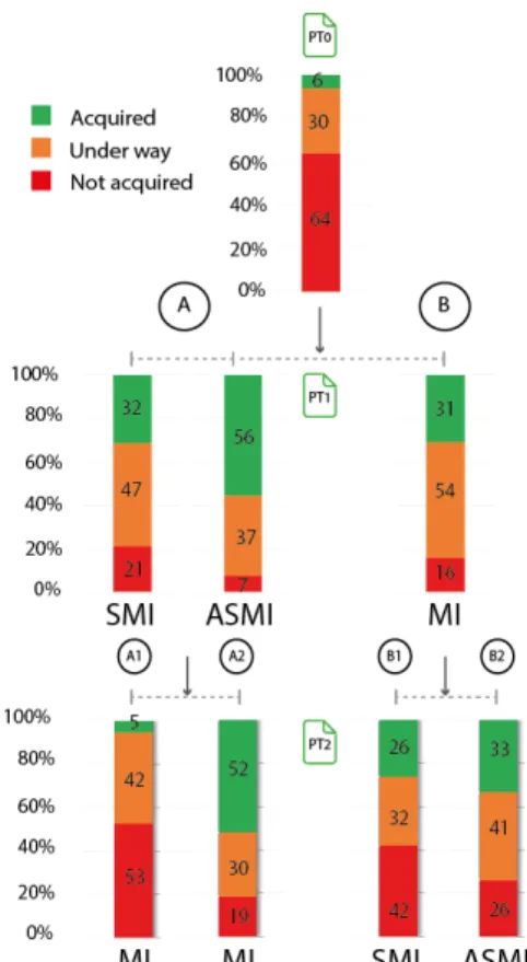
3.88±1.17). The ratio of students with insufficient knowledge decreased in all groups, as illustrated in Figure 11.
The ANOVA also revealed that there is an effect of the learn-ing condition on the scores obtained in PT1 (F[2,86]=3.51, p=0.03, hG2=0.04). A Tukey’s pairwise test showed that the
scores obtained in the ASMI condition (4.44±0.77) are signif-icantly higher than the ones obtained in the other conditions (MI: 3.67±1.26 (p=0.02) —SMI: 3.63±1.16 (p=0.05)). This confirms that augmentations enhance the building of the tar-geted knowledge (H2). On the other hand, no significant differences were found between SMI and MI (p=0.99), which does not contradictH1. The ratio of students having acquired the knowledge is comparable in both conditions (Figure 11, second line). The typologies of errors were very similar (e.g. error of mirror angulation and error of distance between the beam splitter and the mirrors). This tends to show that the SMI condition reproduces closely the MI one.
Post-test PT2
We observed the evolution of the scores from PT1 to PT2 (see Table 3 and Figure 11). A two-factor mixed ANOVA showed that, for group A2, no significant differences were found (F[1, 24]=0.88, p=0.36, hG2=0.04). This tends to indicate that the
students who have learned with ASMI did not decrease their performance when moving to MI. Their scores remain higher than any other conditions. These students gained most of the understanding and skills required to calibrate and troubleshoot
Groups A1 A2 B1 B2
PT0 (Mean±SD score, max=5)
Target knowledge 2.63±1.21 2.59±1.12 2.86±1.25 2.11±1.28 General definitions 1.66±0.69 1.81±0.95 1.86±0.68 1.51±0.79
PT1 (Mean±SD score, max=5)
Target knowledge 3.63±1.16 4.44±0.77 3.72±0.89 3.63±1.47 General definitions 3.18±0.68 3.28±0.68 3.39±0.46 2.92±0.71
PT2 (Mean±SD score, max=5)
Target knowledge 2.32±1.38 4.12±1.13 3.11±1.49 3.48±1.55 General definitions 3.58±1.09 3.97±0.88 3.92±0.81 3.81±1.00
Table 3. Knowledge scores for the pre-test (PT0), and the post-tests (PT1 and PT2).
Figure 11. Learning results as ratios of students being at different levels of knowledge and skills acquisition—before the experiment (first line), after the first training session (second line), and after the second training session (third line)
setups used to make interferometry observations. It seems to indicate a stabilization of their learning; the knowledge that has been built with ASMI could be reinvested effectively with a classical interferometer. This would go in the direction of H3.
On the other hand, for group A1, i.e. the students who expe-rienced with MI after having learned with SMI, a two-factor mixed ANOVA highlighted an unexpected result. In this group, the learning achievement significantly decreased (F[1, 18]=8.92, p=0.01, hG2=0.33, see Table 3). This partly refutes
H3. The amount of students who were underway or without any clear acquisition was quite similar to those noticed in PT0. We observed that 20% of the A1 students did not answer to all the questions of PT2. They rushed their work or did a lot of basic mistakes. In comparison, this ratio was between 2 and 6% for all the other groups. A1 was the group that indicated the lowest motivational advantage to use a hybrid system compared to a standard Michelson interferometer in their UX results (see next section). Therefore, it appears as if they were demotivated. That leads us to the idea that these results could probably be linked to the hope the students put in simulator to support their learning. It might destabilize their first understanding noticed in PT1 and act as a disruption in the learning process by stating that they still had some difficulties to setup the classical Michelson interferometer even if they trained on a simulator just before. This needs to be confirmed
by further analyzes and replications of the experiment. How-ever, it opens the question of the students representation of the role of a simulator in educational context.
For the groups that have initially started with MI, no noticeable improvement can be observed after using SMI (B1) nor ASMI (B2). It tends to show that the augmentations that have shown undeniable benefits after PT1 (group A2), have little impact when activated in a second round of training session. Students may mainly built their knowledge during the first training session, where no augmentation were available. However, it worth noting that the typology of mistakes were different between the two groups. For instance, in the group using SMI at the second round (B1), 37% of the students forget to position the lens and the compensator. This indicates that they did not perceive the role of these components. At the opposite, with ASMI (B2), most of the mistakes were only due to incomplete annotations of the diagrams.
The results obtained for the questions that were not directly linked to the targeted knowledge and skills (i.e. general defini-tion and mathematical exercises) for each step of the learning process (PT0/PT1/PT2) did not show any significant differ-ences between the four groups. Additionally, all teachers confirmed the absence of notable modifications on their teach-ing practices induced by the study conditions (5.83±1.60; 7 being “fully similar”). Moreover, the participants declared that they were not stressed during the study (students: 1.21±0.63; teachers: 1.66±0.81, 7 being “fully stressed”). All these re-sults allow us to exclude a group effect; the observed learning evolutions are due to the system only.
Understanding the role of the augmentations
To gain insight on the relevance of the augmentations, we have looked at the declared perceptions of the ASMI users (groups A2 and B2) and the declared perception of the SMI ones (groups A1 and B1). A one-way ANOVA was performed for each of the asked questions. The ASMI users perceived the tool as less complex to operate than the SMI users, in compar-ison with the MI condition (F[1, 92]=12.66, p<0.01, hG2=0.12
- see Figure 12). Similarly, the augmented version was per-ceived as more motivating (F[1, 91]=10.98, p<0.01, hG2=0.11),
and more efficient (F[1, 74]=25.80, p<0.01, hG2=0.26) than a
tool without augmentation (see Figure 12).
Among the augmentations, the indications displaying the state of the manipulated components (Figure 6(a)) were the ones that the ASMI students cited first (69% of the them). 5 of the 6 teachers reported that they considered this augmentation as the most important. The students and the teachers also endorsed the schematic projections of the wave interferences (Figures 6(b) and 7).
A large majority of the ASMI users (91%) declared that the system they used have met or totally met their needs to their learning goals (5.95±1.15, 7 being “fully agree”). In compar-ison, the mean score for the SMI users is 4.19±1.54. About this question, the open-ended spontaneous answers (multiple answers were possible) of the ASMI users were that the sys-tem i) helped them to understand the theoretical aspect of the interferometry phenomena (49% of the answers), ii) supported
* * *
Figure 12. Results of the UX questionnaire (selected questions). The symbol * indicates statistical significant differences between SMI and ASMI.
or enhanced their cognitive conception (conceptualization) of the wave phenomena (32%), iii) highlighted the causal effect between their interferometer adjustments and the observed in-terference patterns (20%), and iv) supported or enhanced their understanding of technical adjustments of an interferometer (14%).
At the opposite, the answers of the SMI users were more neutral. They rarely declared pedagogical gains compared to the MI condition, except for the restart functionality. Regarding the perceived attractiveness, the students of the ASMI condition found the system really appealing both for its pragmatic and hedonist attributes. Based on the Hassenzhal’s model [10] applied on the Attrakdif results, the augmented version of HOBIT appears as a desirable pedagogical tool (see Figure 13). In contrast, the students of groups A1 and B1 who did not experienced augmentations were a bit less enthusiastic. The answers of the students are in line with the teachers com-ments. Teachers reported that the ASMI students were more motivated and engaged than the SMI ones. Three of them indicated that many of the SMI students did not perceived the added value of a simulated system without augmentations. All the teachers agree that the augmented version of HOBIT is much more interesting than a version without augmentations. The pedagogical augmentation seems to be necessary to sup-port students in their understanding of technical specificities of the interferometer configurations and on their adjustments.
Figure 13. Perceived attractiveness of SMI and ASMI from the Attrak-diff survey [10].
Each user constructs his or her personal representation of the system by defining (consciously or not) various attributes. The high perception of usefulness and attractiveness provided by the pedagogical augmentations, and the perception of the users that the system addresses their needs, could explain the fact that the ASMI group obtained the best learning results. To strengthen these results, new experiments should be con-ducted to assess how the acquired knowledge stabilizes over long periods of time.
DISCUSSION AND CONCLUSION
To overcome the limitations of standard setups, we developed a hybrid platform, HOBIT, which allows us to mimick true optics experiments. This platform reduces the cost as well the setup and maintenance time as no real optical components are used. Beyond the simulation, we showed that HOBIT offers the opportunity to augment the experiment with pedagogical supports. A study conducted in an ecological situation allowed us to demonstrate that such an approach, which mixes simu-lation of the real phenomena and virtual augmentations, en-hances the learning of students compared to traditional setups. HOBIT does not aim at fully replacing true optics experiments. Similarly to a flight simulator, this platform makes training sessions more convenient. Because we took care to mimic as much as possible the real condition, and because we em-bed relevant augmentations within the simulation, the good transfer to the real condition is favored.
In this work we focused on the Michelson interferometer ex-periment. HOBIT is not limited to this particular exex-periment. Numerous other augmented optics experiments can be de-signed from this platform. As an example, we are currently building new pedagogical activities for simulating and aug-menting Young’s interferometer and polarization experiments. Beyond optics, a similar approach could benefit other domains. This is notably the case of scientific fields were the visual-ization of abstract concepts is important. With augmented information it is possible to create new representations that can help students to observe those abstract concepts or invis-ible phenomena [31]. For example, in the electronics field, an efficient learning and understanding of complex concepts remains a challenge.
We hope that our work will help practitioners to design new relevant learning environments in a variety of fields. To this end, we would like to remind the importance of taking into account the nature of the scientific knowledge and the peda-gogical orchestration of practical works at the early stages of the technological design process. Co-design with experts and teachers of the targeted field is a key element for the design of meaningfulness systems that remain as close as possible to the real experiences. We also encourage evaluations in ecological situations, as we did with HOBIT. Both quantitative com-parative studies and UX surveys help gaining insights about the factors that play significant roles in learning. Finally, we would like to remind that a technological enhanced tool in and of itself is not necessarily a golden bullet that enhances learning. Without proper pedagogical support, it can actually backfire, as we have shown in our study.
In this paper, we have focused on the evaluation of the learn-ing efficacy by looklearn-ing at the individual performances of the students. Beyond these performances, it would be interesting to explore how a system like HOBIT modifies the interactions between the students, and how it impacts teaching practices. Indeed, education has to be considered in a larger spectrum than learning performance only. This is one axis of develop-ment of our current work.
We hope that the approach we have described in this paper will open the way to a new generation of hybrid pedagogical systems used in real conditions at schools or at Universities. ACKNOWLEDGMENTS
The authors would like to thank the persons who participated to this project (Benoit Coulais, J´er´emy Bergognat, Patrick Reuter, David Lacoste) as well as the teachers and students who participated to the study. This work was financially sup-ported by Idex Bordeaux (CPU and LAPHIA) and Inria. REFERENCES
1. Oliver Bimber and Ramesh Raskar. 2005. Spatial Augmented Reality: Merging Real and Virtual Worlds. A. K. Peters, Ltd., Natick, MA, USA.
2. Chris Chiaverina and Michael Vollmer. 2005. Learning Physics from the experiments. In Informal Learning and Public Understanding of Physics, Selected Contributions of the 3rd International Girep Seminar. 185–190. 3. Vernon Curran, Lynn Casimiro, Valerie Banfield, Pippa
Hall, Kelly Lackie, Brian Simmons, Manon Tremblay, Susan J Wagner, and Ivy Oandasan. 2009. Research for Interprofessional Competency-Based Evaluation (RICE). Journal of Interprofessional Care 23, 3 (2009), 297–300. 4. Debnath D, Barthakur N. K, Baruah R. S, and Goswami P. K. 2012. Problems of Teaching Optics in Middle School: A Survey in Batadraba Education Block of Nagaon District, Assam, India. International Journal of Scientific and Research Publications 2, 8 (2012).
5. Pierre Dillenbourg, Michael J Baker, Agnes Blaye, and Claire O’Malley. 1995. The evolution of research on collaborative learning. Learning in Humans and Machine: Towards an interdisciplinary learning science. (1995), 189–211.
6. Blizak Djanette and Chafiqi Fouad. 2014. Determination of University Students’ Misconceptions about Light Using Concept Maps. Procedia - Social and Behavioral Sciences 152 (2014), 582–589.
7. Son Do-Lenh, Patrick Jermann, Amanda Legge, Guillaume Zufferey, and Pierre Dillenbourg. 2012. TinkerLamp 2.0: Designing and Evaluating
Orchestration Technologies for the Classroom. Springer, Berlin, Heidelberg, 65–78.
8. Andreas D¨unser, Lawrence Walker, Heather Horner, and Daniel Bentall. 2012. Creating interactive physics education books with augmented reality. In Proceedings of OzCHI ’12. 107–114.
9. Taciana Pontual Falc˜ao and Sara Price. 2009. What Have You Done! The Role of ’Interference’ in Tangible Environments for Supporting Collaborative Learning. In Proceedings of CSCL’09 - Volume 1. 325–334.
10. Marc Hassenzahl. 2005. The Thing and I: Understanding the Relationship Between User and Product. Springer Netherlands, Dordrecht, 31–42.
11. Dana Hayes, Craig Turczynski, Jonny Rice, and Michael Kozhevnikov. 2013. Virtual-Reality-Based Educational Laboratories in Fiber Optic Engineering. In ETOP 2013 Proceedings. EWP40.
12. Edwin Hutchins. 2000. Distributed cognition.
International Encyclopedia of the Social and Behavioral Sciences. Elsevier Science (2000).
13. Carine Lallemand, Vincent Koenig, Guillaume Gronier, and Romain Martin. 2015. Cr´eation et validation d’une version franc¸aise du questionnaire AttrakDiff pour l’´evaluation de l’exp´erience utilisateur des syst`emes interactifs. Revue Europ´eenne de Psychologie
Appliqu´ee/European Review of Applied Psychology 65, 5 (2015), 239–252.
14. Xiaolai Liu and Qinghuai Li. 2011. Combination of the Research-Based Learning Method with the Modern Physics Experiment Course Teaching. International Education Studies 4, 1 (2011), 101–104.
15. Xiangchun Ma, Shaochun Zhong, Da Xu, and Chunhong Zhang. 2010. The Design and Implementation of Middle School Physics Optical Simulation Experiment Platform. In Entertainment for Education. Digital Techniques and Systems: 5th International Conference on E-learning and Games, Edutainment. Springer Berlin Heidelberg, Berlin, Heidelberg, 84–91.
16. Robin Millar. 1987. Towards a Role for Experiment in the Science Teaching Laboratory. Studies in Science Education 14, 1 (1987), 109–118.
17. Robin Millar. 2004. The role of practical work in the teaching and learning of science. Paper prepared for the Committee on High School Science Laboratories: Role and Vision. National Academy of Sciences.
18. Barbara Nye, Spyros Konstantopoulos, and Larry V. Hedges. 2004. How Large Are Teacher Effects?
Educational Evaluation and Policy Analysis 26, 3 (2004), 237–257.
19. Gorazd Planinsic. 2010. Stimulating scientific reasoning through explorations of simple experiments. In
Proceedings of selected papers of the GIREP -ICPE-MPTL International conference. 34–42. 20. Marcelo Rodrigues and Paulo Sime˜ao Carvalho. 2014.
Teaching optical phenomena with Tracker. Physics Education 49, 6 (2014), 671.
21. Richard M. Ryan and Edward L. Deci. 2000. Intrinsic and Extrinsic Motivations: Classic Definitions and New Directions. Contemporary Educational Psychology 25, 1 (2000), 54–67.
22. Magdalena Sadowska and Anna Kami´nska. 2010. Problems in teaching physics in primary and secondary school, as seen by young Polish she-teachers. In Proceedings of selected papers of the GIREP -ICPE-MPTL International conference. 180–185. 23. Brett E. Shelton and Nicholas R. Hedley. 2004. Exploring
a Cognitive Basis for Learning Spatial Relationships with Augmented Reality. Technology Instruction Cognition and Learning 1, 4 (2004), 323 – 357.
24. Osamu Takayama, Armand Niederberger, Petru
Ghenuche, Manoj Mathew, and Giovanni Volpe. 2007. El Dia de la Luz (the Day of Light): two hours optics demonstration for secondary school students. In Tenth International Topical Meeting on Education and Training in Optics and Photonics. 96650K–96650K.
25. Josef Trna. 2005. Motivation and Hands-on Experiments. In Proceedings of the 2nd International Conference on Hands-on Science. 169–174.
26. Josef Trna and Petr Novak. 2010. Motivational Effectiveness of Experiments in Physics Education. In Proceedings of selected papers of the GIREP -ICPE-MPTL International conference. 409–417. 27. Josef Trna, Eva Trnova, and Petr Novak. 2010.
Improvement of science and technology literacy by means of ICT-based collaborative action research including hands-on experiments. In Proceedings of the 7th International Conference on Hands-on Science. 131–137.
28. John Underkoffler and Hiroshi Ishii. 1998. Illuminating light: an optical design tool with a luminous-tangible interface. In Proceedings of the SIGCHI conference on Human factors in computing systems - CHI ’98. 542–549. 29. Stella Vosniadou, Christos Ioannides, Aggeliki
Dimitrakopoulou, and Efi Papademetriou. 2001. Designing learning environments to promote conceptual change in science. Learning and Instruction 11, 4 (2001), 381–419.
30. Jacob O. Wobbrock, Leah Findlater, Darren Gergle, and James J. Higgins. 2011. The Aligned Rank Transform for Nonparametric Factorial Analyses Using Only Anova Procedures. In Proceedings of the SIGCHI Conference on Human Factors in Computing Systems (CHI ’11). 143–146.
31. Hsin-Kai Wu, Silvia Wen-Yu Lee, Hsin-Yi Chang, and Jyh-Chong Liang. 2013. Current status, opportunities and challenges of augmented reality in education. Computers & Education 62 (2013), 41–49.
32. Takeshi Yamaguchi and Hiroshi Yoshikawa. 2013. New education system for construction of optical holography setup Tangible learning with Augmented Reality. Journal of Physics: Conference Series 415, 1 (2013), 12064.
33. Susan A Yoon and Joyce Wang. 2014. Making the Invisible Visible in Science Museums Through Augmented Reality Devices. TechTrends 58, 1 (2014),
![Figure 13. Perceived attractiveness of SMI and ASMI from the Attrak- Attrak-diff survey [10].](https://thumb-eu.123doks.com/thumbv2/123doknet/12998997.379843/10.892.477.778.845.1057/figure-perceived-attractiveness-smi-asmi-attrak-attrak-survey.webp)
