HAL Id: cea-02933399
https://hal-cea.archives-ouvertes.fr/cea-02933399
Submitted on 8 Sep 2020
HAL is a multi-disciplinary open access
archive for the deposit and dissemination of
sci-entific research documents, whether they are
pub-lished or not. The documents may come from
teaching and research institutions in France or
abroad, or from public or private research centers.
L’archive ouverte pluridisciplinaire HAL, est
destinée au dépôt et à la diffusion de documents
scientifiques de niveau recherche, publiés ou non,
émanant des établissements d’enseignement et de
recherche français ou étrangers, des laboratoires
publics ou privés.
To cite this version:
M Gentili, B. Fontaine, G. Rimpault. Evaluation of SFR Deformed Core Reactivity. ICAPP 2015
-International Congress on Advances in Nuclear Power Plants, May 2015, Nice, France. �cea-02933399�
Evaluation of SFR Deformed Core Reactivity
M.Gentili1,2, B.Fontaine1, G. Rimpault1
1 CEA, DEN, DER, Cadarache 13108 Saint Paul Lez Durance, France 2Aix Marseille Université, 13284, Marseille, France
*e-mail to: [email protected]
Abstract –
In the framework of the development of the Sodium Fast Reactor technology (SFR) the analysis of all possible scenarios leading to perturbation of nominal operating condition is exploited. Among these scenarios attention is being paid on reactivity modification due to core assemblies bowing and deformation, and to lattice readjustments consequent to earthquakes. A computational scheme based on the spatial projection method fulfilling a good compromise between the accuracy of stochastic codes and the quick runtime of deterministic codes has been developed and used to determine the reactivity changes issued from core lattice deformations and irregularities. The calculation of reactivity changes induced by core deformation is achieved by modifying the isotopic concentrations of assemblies concerned by displacements, by projecting the deformed lattice geometry on that corresponding to regular reference case. This methodology was validated by comparison with stochastic codes, and good agreements between the results achieved and those obtained by the Monte Carlo code TRIPOLI4 are observed. The deterministic code available at CEA for fast reactors, i.e. ERANOS/PARIS, has been used to solve neutron transport equation in a full 3D core representation and to calculate the reactivity changes due to core flowering and compaction. In this work, such a method has been used to determine the maximal positive/negative reactivity insertion corresponding to a postulated mechanical energy supplied to an SFR core, as much as the lattice deformation causing it. The results presented in this paper, represent a first step in the assessment of a favourable calculation scheme that can be easily scaled-up to large-sized core and used for the future application in core design and safety analysis.I. INTRODUCTION
Fast reactor designs are currently being revisited aiming at having a consolidated safety dossier. In that frame, studying any perturbation of nominal operating condition is mandatory1.
Among different initiators, particular attention is being paid on reactivity insertion due to core assemblies bowing and deformation and induced lattice readjustments as consequence of events such as earthquakes2.
In the case of a SFR core, significant reactivity increases consequently to core compaction may arise. In fact because of the gaps between the assemblies the most reactive configuration differs from normal operation conditions.
Even if stochastic codes based on Monte Carlo method allow a precise evaluation of core reactivity in its deformed configuration, the long computation time and the significant needs of memory needs they are characterized by, do not make such a method compatible for core design
iteration process, which require many core deformation situations, or for seismic response simulations. On the other hands deterministic codes guarantee reduced costs in terms of simulations run time, preventing although stochastic codes precision to be achieved.
In this work, a first approach in the estimation of an SFR core lattice deformation maximizing positive and negative reactivity insertion, as a function of the mechanical energy provided to the reactor core is presented. An a-priori evaluation of ∆𝜌 has been fulfilled starting from individual assemblies displacement reactivity worth, issued from ERANOS3 perturbation module
coupled with a deterministic computation scheme based on mesh projection method.
A precise description of assemblies mechanical interaction is not the purpose of this work, which is mainly focused on proposing a first neutronic approach for an
a-priori estimation of deformed core reactivity.
In the following sections a description of the deterministic computation scheme developed for reactivity
French SFR prototype Phénix4.
II. LOCAL LATTICE DEFORMATIONS IMPACT ON SFR CORE REACTIVITY
A simplified model5 has been proposed by the authors
with the purpose of identifying the impact of different neutronic phenomena affecting reactivity in case of local deformation of the hexagonal assembly lattice for a SFR. In this section a brief summary of the model is proposed and attention will be pay on core reactivity changes issued from individual assembly shifting, as a function of the assembly nature and position into the core, as well as its dependence from displacement direction and intensity.
Fig. 1. Assembly displacement 2D representation and local changes in sodium (𝑁𝑁𝑎) and in assembly isotopes (𝑁𝐴𝑠𝑠,𝑖)
concentration.
For sake of simplicity different assumptions have been made in developing the model:
One energy group;
Diffusion approximation6; First order perturbation theory;
Microscopic cross sections not affected by the perturbation.
For the purpose of this work, the assumptions made guarantee the dependence of individual assembly reactivity worth by its displacement or deformation to be determined without lack of precision. Nevertheless such hypothesis can be easily relaxed in order to determine precisely the nature of different contributions to ∆𝜌 as functions of the lattice deformation considered5,7.
characterized by deformation axial gradient different from zero.
Referring to Fig. 1. an assembly displacement involves local changes and redistribution of isotopic concentration and so of macroscopic cross sections 𝛴. In particular, since first order perturbation theory8 is used (𝛷
𝑝𝑒𝑟𝑡 ≅ 𝛷𝑢𝑛𝑃𝑒𝑟𝑡 )
and isotopic microscopic cross sections are retained to be not affected by lattice deformations, changes in macroscopic cross sections of isotope 𝑖 for the reaction 𝑗 will be:
𝛿𝛴𝑖,𝑗= 𝛿𝑁𝑖𝜎𝑖,𝑗 (1)
Again, it follows that the perturbation will affect just volumes 𝑉𝐴,ℎ and 𝑉𝐵,ℎ, implying perturbation integrals to
be null outside these spatial domains.
In order to determine the reactivity change induced by an assembly displacement in the direction 𝑢⃗⃗⃗⃗⃗⃗⃗ , a small 𝑑,ℎ
deformation approximation is introduced. In particular we consider that for an assembly whose center projection on 2D plane is 𝑃(𝑥, 𝑦), the perturbation is negligible (𝑁𝑖,ℎ≫
𝛿𝑁𝑖,ℎ) and localized in the regions 𝑃𝐴 and 𝑃𝐵 around the
displaced assembly. Furthermore In a 1D representation along the displacement axis, the distance between 𝑃𝐴 and
𝑃𝐵 will be:
‖𝑃𝐴− 𝑃𝐵‖ℎ= 𝑠𝑢⃗⃗⃗⃗⃗⃗⃗ (2) 𝑑,ℎ
where 𝑠 is the size of the assembly.
With a short-cut in notation we can define: 𝛿𝑁𝑖ℎ(𝑃) = 𝛿𝑁𝑖,ℎ𝛿(𝑃 − 𝑃𝐴𝑠𝑠)
∫ 𝛿𝑁𝑉 𝑖ℎ(𝑃)𝛷(𝑃) = 𝛿𝑁𝑖,ℎ𝛷(𝑃 − 𝑃𝐴𝑠𝑠) (3)
where 𝑃𝐴𝑠𝑠 represents the assembly center and,
because of the assumptions made, the neutronic flux results to be just a function of space.
By combining equations (1), (2), (3) and first order perturbation theory formulation, and considering a first-order expansion for neutronic flux 𝛷 and its adjoint 𝛷∗ ,
the reactivity variation induced by a fuel assembly centered in 𝑃(𝑥, 𝑦) will be5:
∆𝜌𝑃= − ∑ 𝐾ℎ 𝑃,ℎ⟨∇(𝜙𝜙∗)𝑃|𝑢⃗ 𝑑,ℎ⟩ (4)
In order to put in evidence the relation between ∆𝜌, assembly position and lattice deformation, the dependence from changes in isotopic concentration is resumed in term 𝐾𝑃,ℎ, function of displacement length |𝑑 |
Fig. 2. Assembly reactivity worth (pcm) for u⃗ d= [ √32;12]
(Phénix core application).
According to diffusion approximation, the term ∇(𝜙𝜙∗)
𝑃 represents the derivative of the product of spatial
direct flux and adjoint flux in radial direction 𝑢⃗ 𝑃= ‖𝑃−𝑃𝑃−𝑃0 0‖,
where 𝑃0= (𝑥0, 𝑦0) represents the core center. It follows
that the directions which maximize and minimize the individual assembly reactivity contribution will correspond to centripetal and centrifugal directions respectively:
max∆𝜌𝑃𝑢⃗ 𝑑= −𝑢⃗ 𝑃 min∆𝜌𝑃𝑢⃗ 𝑑= 𝑢⃗ 𝑃 (5)
Exceptions will arise for control rods assemblies or those in correspondence of fertile/reflector interfaces, where max( 𝑢⃗ 𝑑) and min( 𝑢⃗ 𝑑) mainly depend mostly by
changes in concentration and by neighboring assemblies nature.
Moreover, because no perturbation in microscopic cross section is considered, and since 𝛷𝑝𝑒𝑟𝑡 ≅ 𝛷𝑢𝑛𝑃𝑒𝑟𝑡, we
can estimate (as first a approximation) deformed core reactivity starting from individual assemblies reactivity contributions:
∆ρ ≅ ∑ ∆ρ𝑃 𝑃 (6)
Fig. 3. reports a comparison between diffusion calculation (DIF3D), transport 𝑆𝑁 calculation (SNATCH)
and an estimation of ∆ρ using (6).
Fig. 3. Reactivity changes induced by the displacement of the two innermost fuel assemblies rings evaluated with spatial projection method.
The more the assemblies displacements are small the more such assumptions, and consequently (6) results to be verified, as reported in Fig. 3. Deviancy from calculated
results in fact, increases as core deformation involves a larger number of assemblies and larger displacements, remaining less than 15% both for diffusion and transport calculations.
III. ASSEMBLIES REACTIVITY WORTH EVALUATION
In order to simulate core lattice deformation and to determinate the assemblies reactivity worth, a computational scheme based on spatial projection method and deterministic codes has been used5.
The perturbations in the reactor lattice are simulated by modifying the isotopic concentrations of those cells which correspond to displaced or deformed assemblies. The perturbed concentrations are calculated by projecting the deformed lattice geometry on the regular one.
Neutron flux and reactivity evaluation issue from a two-step approach necessary to reduce the number of variables required to describe precisely core heterogeneities and geometric complexity, providing first an estimation cross sections resonances and self-shielding phenomena, and then the resolution of both diffusion or transport equation starting from macroscopic cross sections previously evaluated.
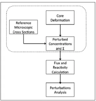
Fig. 4. Calculation scheme representation.
As represented in Fig. 4., once microscopic cross sections for each core region are calculated, changes in macroscopic cross sections are evaluated according to (1), starting from variations in isotopic concentrations issued from a core deformation, provided as an input in terms of assemblies displacements.
For this work the self-shielded microscopic isotopic cross sections for 33 energy groups have been calculated with ECCO9 cell code for fast reactors, referring to the JEFF3.110 neutronic data library.
The ERANOS perturbations module based on DIF3D3
solver has been used to evaluate changes in ∆ρ consequent to single assembly shifting in several directions and in correspondence of different core regions and configurations.
Confirmations of (4) have been achieved identifying the inward/outward direction to be the one maximizing/minimizing ∆𝜌𝑃.
The individual contributions of Phénix assemblies in inward direction, corresponding to 1 𝑚𝑚 displacement are reported in Fig. 5. For the sake of simplicity, because of the core symmetrical geometry and assembly nature, a sixth-core representation is reported.
Referring to the Phénix core the deformations and displacements which mostly affect core reactivity involve assemblies concerning interface regions, as fissile/fertile interface and fertile/reflector ones.
Fig. 5. Phénix core Assembly Reactivity Worth (pcm) for max∆𝜌𝑃𝑢⃗ 𝑑 and |𝑢⃗ 𝑑| = 1 𝑚𝑚 (Phénix core application).
IV. CORE DEFORMATION REACTIVITY ESTIMATION
In this section an iterative method based on individual assemblies reactivity worth is proposed, in order to provide an a-priori estimation of reactivity insertion consequent to a core lattice deformation.
In particular, such a method as been applied with the purpose of determining the assemblies displacements field which maximizes/minimizes ∆ρ in correspondence of the mechanical energy 𝐸 supplied to the core.
As a first approach, this work does not deal with a precise description of assemblies mechanical interaction and its relationship with the energy supplied to the reactor core. Its purpose is to show instead how the most reactive core deformation can be estimated just starting from individual assembly reactivity worth.
In this work no assemblies bowing or bending is considered. To take into account these phenomena, ameliorations of the method will be object of future works.
For these reason several assumptions concerning the problem mechanical formulation have been taken into account:
No friction interactions between assemblies have been considered;
The sodium flow does not provide any mechanical resistance to assemblies displacement;
Hence: the total energy supplied to the core concerns assemblies displacements. Just assemblies potential energy is considered.
All core assemblies have the same mechanical properties, expressed in terms of 𝑘 [𝑁 𝑚𝑚⁄ ].
As stated in chapter III, because of Phénix4
symmetrical core configuration, the evaluation of assemblies reactivity worth has been fulfilled in correspondence of a sixth part of the whole core, and for 24 displacement directions.
A first order approximation has been then used to calculate ∆ρ𝑃 as a function of assembly displacement
module |𝑢⃗ 𝑑,𝑃|. In fact, because of the dependence of
isotopic concentrations changes and 𝐾𝑃 (4) from the
displacement length, it is possible to write:
∆𝜌𝑃 ≅ 𝛼|𝑢⃗ 𝑑,𝑃|- 𝛽|𝑢⃗ 𝑑,𝑃| 2 𝛼 ≫ 𝛽 (7)
Identifying ∆ρ𝑃,1(𝜗𝑑,𝑃) as the reactivity variation
induced by an assembly shift of |𝑢⃗ 𝑑,𝑃| = 1 𝑚𝑚 in the
direction 𝜗𝑑 it follows:
∆𝜌𝑃(|𝑢⃗ 𝑑,𝑃|, 𝜗𝑑,𝑃) = |𝑢⃗ 𝑑,𝑃|∆ρ𝑃,1(𝜗𝑑) (8)
According to the assumptions previously made, all the energy supplied to the core concern the assemblies shifting from their original position:
𝐸 =12𝑘 ∑ |𝑢⃗ 𝑃 𝑑,𝑃| 2 (9)
Checks on the distance between assemblies are carried at each iteration, in order to let the geometrical configuration that guarantees the maximal reactivity insertion, to be a physical lattice deformation. Then:
∆ρ𝑀𝑎𝑥= max𝐸∑ |𝑢⃗ 𝑃 𝑑,𝑃|∆ρ𝑃,1(𝜗𝑑,𝑃) (10)
Since the reactivity worth of each assembly has been evaluated just for 24 displacement directions, the direction maximizing ∆ρ𝑃,1 is considered. Equation (9) becomes
therefore:
∆ρ𝑀𝑎𝑥= max𝐸∑ |𝑢⃗ 𝑃 𝑑,𝑃|∆ρ𝑃,1(𝜗𝑀𝐴𝑋,𝑃) (11)
In particular, the most reactive core deformation results to be characterized by a displacements field which is directly proportional to assemblies individual contributions: |𝑢⃗ 𝑑,𝑃|𝑀𝐴𝑋= 𝛾∆ρ𝑃,1(𝜗𝑀𝐴𝑋,𝑃).
It follows that:
∆ρ𝑀𝑎𝑥= 𝛾∑ [∆ρ𝑃,1(𝜗𝑀𝐴𝑋,𝑃)] 2
𝑃 (12)
where the constant 𝛾 is a function of the energy considered.
The same procedure is used to determine the minimal reactivity insertion corresponding to the energy 𝐸.
The impact of approximations (8) and (11) on estimation of deformed core reactivity will be discussed later in this paper.
IV.A Maximal Positive Reactivity Insertion In this section a comparisons between the estimated maximal reactivity insertion and the results issued from deterministic calculations is reported.
Such an analysis has been fulfilled taken into account two main parameters:
The minimal distance allowed between hexagonal wrappers of fuel assemblies.
The mechanical properties of fuel assemblies expressed by term 𝑘.
In fact, since in the model no assemblies pad have been considered, their presence can be approximatively taken into account by considering different values of sodium gap between the assemblies. Furthermore suggestions about the impact of pad deformation resistance to ∆ρ have been achieved by using different values of 𝑘.
The first scenario considered deals with the absence of assembly pads.
In particular the sodium gap (∆𝑙 = 3.5 𝑚𝑚) and mechanical resistance (𝑘 = 1000 [𝑁 𝑚𝑚⁄ ]) considered in this scenario refer to Phénix core properties in its nominal state4.
The deformation considered involves fuel and fertile assemblies, while no reflector assemblies displacements are considered.
For the sake of simplicity hereunder a comparison is reported for deformations for which ∆ρ ≤ 1$ (1$ ≅ 350 pcm).
To be specific, in core design activities, this values (1$) is retained to be the maximal reactivity that can be inserted into the core in case of its deformation11.
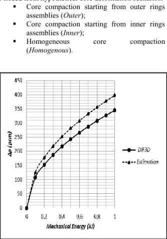
As displayed in Fig. 6, the a-priori approach overestimate the deterministic results, issued from reactivity calculation in correspondence of the deformed geometry.
As mentioned before, such a deviancy from calculations arises from assumptions (8) and (11). Reduced deviancies could be achieved with a finer description of ∆𝜌𝑃,1(|𝑢⃗ 𝑑,𝑃|, 𝜗𝑑,𝑃), involving a larger number of
displacement directions, as much as the introduction of the second order term in ∆𝜌𝑃 dependence from the
Core compaction starting from outer rings assemblies (Outer);
Core compaction starting from inner rings assemblies (Inner);
Homogeneous core compaction (Homogenous).
Fig. 6. Comparison between maximal reactivity insertions estimated and calculated with ERANOS DIF3D solver.
Even for these scenarios, the reactivity changes induced by deformation have been estimated starting from each assembly contributions by using (6).
In particular, the homogeneous core compaction is usually considered as the reference deformation in the perspective of the respect of safety issues in core design activities.
As reported in Fig. 7. in the range of energies considered, a core deformation concerning assemblies compaction starting from inner rings and progressively involving outer assemblies (Inner), leads to values of ∆𝜌 broadly smaller than the one involving outer assemblies (Outer). As reported in Fig. 5 in fact, inner assemblies are characterized both by smaller values of ∆𝜌𝑃,1 than those
located in fifth and sixth ring.
Again, the reactivity insertion consequent to a
homogenous core compaction is slightly inferior to that the Most Reactive one, issued from (11). By comparing these
two kinds of deformation it follows that, referring to the assumptions made, a 1$ insertion is attained at lower energies for the Most Reactive configuration (≅ 0.1 𝑘𝐽 lower).
𝛿𝜌 = ∆ρ𝑀𝑅(𝐸1$,𝑀𝑅)−∆ρ𝐻𝑜𝑚(𝐸1$,𝑀𝑅) (13)
as the deviancy between the two models in correspondence of the energy at which the Most Reactive configuration (MR) is concerned by a 1$ reactivity insertion. In this case 𝛿𝜌 ≅ 5%.
All the scenarios converge to the same values of ∆ρ = 3.73 $ when a full core compaction (∆𝑙 → 0 𝑚𝑚) is
considered (𝐸 = 12.225 𝑘𝐽).
Fig. 7. Maximal reactivity insertion issued from different deformations scenarios.
As previously stated, the presence of assembly pads has been taken into account trough different values of the sodium gap length ∆𝑙. For this analysis just the most reactive configuration has been considered (Most
Reactive).
Since the trends of ∆ρ𝑀𝑎𝑥 overlap for the pad sizes considered, just the maximal reactivity insertion corresponding to the most compact core configuration (∆𝑙 = 0), as much as the mechanical energy supplied to attain ∆𝜌 = 1$, is reported in Tab. 1.
Smaller the assembly gaps smaller the assemblies displacements and therefore smaller values of ∆ρΔl=0.
Conversely, 𝐸1$ increases slightly with the presence of
pads and a 1$ insertion is never reached for ∆𝑙 → 0 . The impact of the presence of pads on 𝛿𝜌 is negligible.
TABLE I
Maximal Core Compaction Reactivity Insertion Gap Between Assembly Pads (𝑚𝑚) 𝐸1$ (𝑘𝐽) 𝐸∆𝑙=0 (𝑘𝐽) ∆ρ∆l=0 (𝑝𝑐𝑚) 0.5 - 0.25 186.5 1.5 0.88 2.25 569.3 2.5 3.5 0.77 0.75 12.23 6.25 1300.8 941.5 In its reference configuration, Phénix core fuel assemblies are equipped with pads that guarantee core compactness at nominal operating conditions. In order to determine the pads deformations and the values of 𝑢⃗ 𝑑,𝑃 that
would lead to core compactness, a complete mechanical investigation should be accomplished. As previously reminded, such an analysis goes beyond the aim of this paper. However, looking at Tab. 1. it is possible to predict how this core configuration would be characterized by smaller values of ∆ρ𝑀𝑎𝑥 and therefore bya safer neutronic behavior.
Furthermore, because of the high amount of energy required to gain the pads elastic resistance, higher values of 𝐸 would be required to attain a core deformation that entails ∆𝜌 = 1$.
Different values of the constant 𝑘 have been taken into account with the purpose of predict, in a preliminary way, the impact of assemblies mechanical properties on ∆𝜌(𝐸).
The effects of both a higher and a lower assemblies resistance to shifting and displacement have been analyzed by increasing and reducing the 𝑘 values.
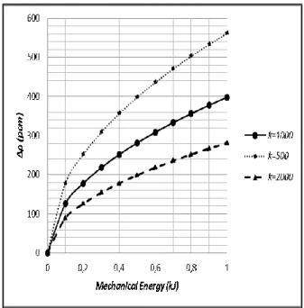
For the sake of simplicity, in Fig. 8 the trends of ∆𝜌(𝐸) is displayed for the reference case (𝑘 = 1000[𝑁 𝑚𝑚⁄ ] ) and for core configuration into which the mechanical constant is reduced/increased by a factor 2.
As suggested by (9), because of the direct proportionality relation between 𝑘 and |𝑢⃗ 𝑑,𝑃|(𝐸), for
configurations foreseeing an increased resistance to deformation (increased pads and lattice stiffness), a larger amount of energy need to be supplied to the core in order to insert 1$ of reactivity.
The opposite trend is observed lower values of 𝑘. As n case of assemblies equipped pads, no remarkable variations of 𝛿𝜌 arise.
Fig. 8. Maximal reactivity insertion in correspondence of different values of the 𝑘. No assemblies pads are considered.
Moreover, the mechanical energy necessary to attain full core compaction (𝐸∆𝑙=0) and a prompt-critical
configuration is reported in Tab. 2.
TABLE II
Maximal Core Compaction Energy as function of 𝑘 𝑘 [𝑁 𝑚𝑚⁄ ] 𝐸1$ (𝑘𝐽) 𝐸∆𝑙=0 (𝑘𝐽)
500 0.39 6.05
1000 0.77 12.23
2000 1.55 24.45
The same tendencies are observed in dealing with pad-equipped assemblies.
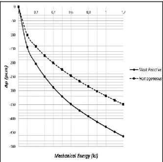
IV.B Maximal Negative Reactivity Insertion The same method has been then applied to determine the maximal negative reactivity insertion (∆ρ𝑀𝑖𝑛 ) inserted into the core because of a lattice deformation. As suggested by (5) such a deformation is characterized by assemblies shifting towards outward directions.
In this section just a comparison between ∆ρ𝑀𝑖𝑛 estimated with the method proposed into this paper and with a homogeneous deformation is proposed. The impact of pad-equipped assemblies and of lattice stiffness has been observed to be comparable to the one evaluated in §IV.A
Conversely from core compaction, a deformation issued from a homogenous core expansion largely differs from the one which maximizes ∆ρ𝑀𝑖𝑛 .
∆ρ𝑀𝑖𝑛= 𝜉∑ [∆ρ𝑃,1(𝜗𝑀𝐼𝑁,𝑃)] 2
𝑃 (14)
As stated by (14) in fact, the deformation will affect first the assemblies with larger ∆ρ𝑃,1(𝜗𝑀𝐼𝑁,𝑃), so the outer
core regions.
On the other hand, in case of homogeneous core expansion, referring to the same amount of energy supplied to the core, the deformation will be affect mostly the inner regions of the core, characterized by lower values of ∆ρ𝑃,1(𝜗𝑀𝐼𝑁,𝑃).
Fig. 9. Maximal negative reactivity insertion. No assemblies pads are considered.
For this reasons the Most Reactive deformation is characterized by broadly inferior values of 𝐸1$ (≅ 0.6 𝑘𝐽
lower than the Homogeneous case), and in respect to core compaction, higher deviancy between the two models is observed for 𝐸1$,𝑀𝑅 (𝛿𝜌 ≅ 28%).
V. CONCLUSIONS
The evaluation of core neutronic behavior consequent to core assemblies bowing and deformation or lattice modifications consequent to earthquakes or impulsive loads, is one of the main challenge fast reactor core designer are faced to.
A precise evaluation of the deformed core reactivity is in fact necessary in order to respect properly reactor safety
Since deterministic scenarios of core deformations are very challenging (seismic local time history, core deformation origin, gap size distribution), some assumptions have to be made in design phases to represent core deformations, with indicative conservative level.
In particular, a homogeneous core geometry modification (both in the sense of core compaction and expansion), is considered usually as the reference deformation taken into account for safety evaluation.
In this work, a simple method has been developed and tested in order to determine the maximal positive and negative reactivity insertion issued from core deformation induced by a postulated mechanical energy supplied to an SFR core. Conversely to the homogeneous case, no
a-priori assumptions concerning the possible deformations
scenario have been made.
A preliminary analysis based on perturbation theory has been fulfilled in order to determine the relation between core assemblies and the reactivity insertion consequent to their displacement. In particular, for small lattice perturbations, the possibility of estimating changes in reactivity of the whole core starting from local contributions is put in evidence.
The deviancy of estimated results from those achieved by DIF3D direct calculation increases as larger assemblies displacement fields are considered. Our method overestimates the reactivity perturbations guaranteeing, from a safety point of view, a conservative estimation of deformed SFR core neutronic behavior. Anyway, discrepancies remain lower than 15 %.
Several hypotheses concerning the mechanical interaction between the assemblies have been done.
Because of these assumptions, the analysis fulfilled in this work cannot provide a precise and complete evaluation of the maximal reactivity insertion attainable as a function of the energy supplied to the core, but it represents a first important step in this direction.
In fact, results put in evidence how homogenous geometry modifications may not be representative of the worst core deformation scenario. Moreover such a scenario, characterized by a displacements field which results directly proportional to individual contributions can be determined simply by starting from local contributions, avoiding any hypothesis on lattice modifications to be done.
The possibility of take into account core different assemblies features, as for instance pad size have been exploited in §IV.A.
In order to improve the method performances, a deeper analysis in core mechanics is necessary, as much as a complete evaluation of ∆𝜌𝑃 allowing the relaxation the
assumption (8) and the description of assemblies bowing or bending.
However, several information on deformed core behavior can be achieved with the method object of this work. In particular, progresses from a safety point of view have been attained because of the possibility of determining the most reactive core configuration simply starting from its neutronic description.
The methodology proposed in this paper represents a first step in the assessment of a favorable calculation scheme that can be easily scaled-up to large-sized core.
REFERENCES
1. GIF DOE-GIF, 2002. “A Technology Roadmap for
Generation IV Nuclear Energy Systems.” Technical
Report GIF2002200, GIF.
2. T. J. MORAN, “Core restraint contributions to radial
expansion reactivity“, ASME/ANS Nuclear Power
Conference, Philadelphia, USA, (1986).
3. G. RIMPAULT et al. “The ERANOS code data system
for fast reactor neutronic analyses”, Proc. of The
Physics of Fuel Cycles and Advanced Nuclear Systems (PHYSOR 2002), Seoul, Korea (2002). 4. J.M. CHAUMONT, D. Goux, L. Martin, “Some safety
related characteristics of Phénix, a 250 MWe fast reactor – 1989 and 1990 negative reactivity trip investigations”, ANP’92: International Conference on
Design and Safety of Advanced Nuclear Power Plants, Tokyo (Japan), October (1992), pp. 25–29.
5. M. GENTILI, B. Fontaine, G. Rimpault, “Deformed
Core reactivity Evaluation with Mesh Projection Based Method”, Nuclear Technology, NT14-123,
(accepted, to be published).
6. A.E WALTAR et al., “Fast Spectrum Reactors”,
Springer, 2012.
7. M. REED, K Smith., B Forget., “The 'virtual density'
principle of neutronics: Toward rapid computation of reactivity effects in practical core distortion scenarios”, Proceedings of the 2013 International
Conference on Mathematics and Computational Methods Applied to Nuclear Science and Engineering - M and C 2013.
8. M. L. WILLIAMS, “Perturbation Theory for Nuclear
Reactor Analysis” CRC Handbook of Nuclear
Reactors Calculations, Vol. III, CRC Press, Inc., Boca Raton, Florida, 1986.
9. G. RIMPAULT. “Physics documentation of ERANOS
and the ECCO cell code”, Technical report, Rapport
Technique RT/SPRC/LEPh 97-001, 1997.
10. A. KONING et al, “The JEFF-3.1 Nuclear Data
Library” Nuclear Energy Agency Data Bank, OECD,
JEFF Report 21, NEA N° 6190, (2006).
11. P. SCIORA, et al., “Low void effect core design
applied on 2400 MWth SFR reactor” – Proceedings of
ICAPP 2011, Nice, France, May 2-5, 2011.
12. B. FONTAINE et al., “Description and preliminary
results of PHÉNIX core flowering test”, Nuclear
Engineering and Design, volume (241), pp. 4143– 4151.