HAL Id: tel-01754790
https://tel.archives-ouvertes.fr/tel-01754790
Submitted on 3 May 2018
HAL is a multi-disciplinary open access
archive for the deposit and dissemination of sci-entific research documents, whether they are pub-lished or not. The documents may come from teaching and research institutions in France or abroad, or from public or private research centers.
L’archive ouverte pluridisciplinaire HAL, est destinée au dépôt et à la diffusion de documents scientifiques de niveau recherche, publiés ou non, émanant des établissements d’enseignement et de recherche français ou étrangers, des laboratoires publics ou privés.
Integrated Circuits of Trusted Systems
Leonel Acunha Guimarães
To cite this version:
Leonel Acunha Guimarães. Testing Techniques for Detection of Hardware Trojans in Integrated Cir-cuits of Trusted Systems. Micro and nanotechnologies/Microelectronics. Université Grenoble Alpes, 2017. English. �NNT : 2017GREAT080�. �tel-01754790�
THÈSE
Pour obtenir le grade de
DOCTEUR
DE L
A COMMUNAUTÉ UNIVERSITÉ
GRENOBLE
ALPES
Spécialité : Nano Électronique & Nano Technologies
Arrêté ministériel : 25 mai 2016
Présentée par
Leonel
ACUNHA GUIMARÃES
Thèse dirigée par Laurent FESQUET
et co-encadreée par Rodrigo POSSAMAI BASTOS réparée au sein du Laboratoire TIMA
dans l’École Doctorale Electronique, Electrotechnique, Automatique &
Traitement du Signal (E.E.A.T.S)
Testing
Techniques for Detection
of
Hardware Trojans in Integrated
Circuits
of Trusted Systems
Thèse soutenue publiquement le 1 décembre 2017, devant le jury composé de :
M. Guy GOGNIAT
Professeur, Université de Bretagne du Sud, Président
M. Giorgio DI NATALE
Directeur de Recherche, LIRMM-CNRS, Rapporteur
M. Lilian BOSSUET
Professeur, Université Jean-Monnet de Saint-Etienne, Rapporteur
M. Laurent FESQUET
Maître de Conférences, Université Grenoble Alpes, Directeur de thèse
M. Rodrigo POSSAMAI BASTOS
Acknowledgement
I would like to dedicate a few words to acknowledge some people who were essential for the accomplishment of this work.
Firstly, I would like to express my sincere gratitude to my advisors Dr. Laurent Fesquet and Dr. Rodrigo Possamai Bastos who gave me the chance to work with them and guided me through this harsh road. Their guidance surely helped me to improve my research and mitigate all the insecurities a PhD student may have. I wish to express my special thanks to Prof. Guy Gogniat, Dr. Giorgio Di Natale, and Prof. Lilian Bossuet who accepted being part of my examining board. Their valuable and constructive feedback certainly counted for improving the quality of this manuscript and the dissertation defense.
I would like to thank all the staff of TIMA Laboratory, EEATS, and CIME Nanotech who always helped me somehow with uncountable issues, specially Alejandro Chagoya. I would like to name a few researchers, PhD and former PhD students who were great fellows whose collaboration impacted decisively in the result of this work: Thiago, Otto, Rodrigo Iga, Jean, Tugdual, Chadi, Amani, Raphael, Matheus, Ricardo, Assia, Karim, Sophie, Grégoire, Sylvain, Arthur, Alexandre, and Ali. Their feedbacks, friendship, and numerous rubber duck debbuging were essential for the final result of this work. I would like to also address special thanks to all my friends I had the pleasure to meet in Grenoble.
I wish to thank my loved ones who I had to stay apart since I decided to move to France: my aunts, uncles, cousins, grandmother, godfather, and all friends in Brazil.
I would like to extend great thanks to my dear Vó Cléia, Vó Joana, and Dinda Nadir who I dedicate this thesis to. I am grateful for your teaching, love, kindness, and affection. I would change everything to pass more time with you.
I would especially like to thank my parents Leonel and Ivana for everything they have done for me, they are the best parents I could have. This work would be nothing without them.
Finally, I wish to thank my beloved girlfriend Natália for her love, friendship, support, and inspiration.
Table of Contents
Abstract xv
Résumé xvii
1 Introduction 1
2 Hardware Trojan Insertion and Detection 5
2.1 Trojan Insertion . . . 5
2.1.1 Trojan Model . . . 7
2.1.2 Trojan Taxonomy . . . 8
2.1.3 Case Studies: Trojans at Different Abstraction Levels . . . 12
2.2 Trojan Detection . . . 15
2.2.1 Destructive: Physical Inspection . . . 17
2.2.2 Functional (Logic) Testing . . . 17
2.2.3 Side-Channel Analysis . . . 18
2.2.4 Run-time Monitoring . . . 24
2.2.5 Combined and Hybrid Methods . . . 24
2.2.6 Trojan Prevention . . . 26
2.2.7 Overall Analysis . . . 26
2.3 Conclusion . . . 27
3 Analysis of Transistor-Level Trojans in Ring Oscillators 29 3.1 Motivation: Attack in RO-based TRNG . . . 30
3.2 Tri-State Trojans on Ring Oscillators . . . 30
3.2.1 Capacitor Trojan . . . 31
3.2.2 Double-Switch Trojan . . . 32
3.2.3 Transmission-Gate Trojan . . . 32
3.3 Trojan results in Ring Oscillators . . . 33
3.3.1 RO Frequency Analysis . . . 34
3.3.2 Power Consumption Analysis . . . 36
3.4 Conclusions . . . 38
4 Bulk Built-in Current Sensors For Detection of Transient Faults 39 4.1 Architectures of Built-In Current Sensors . . . 40
4.1.1 Single BBICS architectures . . . 42
4.1.2 BBICS architectures of Neto et al. . . 44
4.1.3 BBICS architectures of Zhang et al. . . 44
4.1.4 Modular BBICS architectures . . . 46
4.1.5 Dynamic BBICS architectures of Simionovski and Wirth . . . 46
4.2 New Dynamic BBICS Architecture . . . 47
4.3 Sensitivity of a Flip-Flop in Detecting Transient Faults . . . 50
4.3.1 Experiments . . . 50
4.3.2 Results and analysis . . . 51
4.4 Results and Analysis of BBICS Sensitivities in Detecting Transient Faults . . . 53
4.4.1 Experiments for sizing BBICS architectures . . . 53
4.4.2 Experiments for analyzing the sensitivities of BBICS architectures . . . 54
4.4.3 Comparative analysis of BBICS detection sensitivities . . . 55
4.4.4 Influence of the monitored area size . . . 57
4.4.5 Estimation of the area overhead imposed by BBICS architectures . . . 58
4.4.6 Corner analysis of BBICS architectures . . . 59
4.5 Conclusions . . . 59
5 Reuse of Bulk Built-in Sensors for Detection of Trojans 61 5.1 Built-in Current Sensors for Generating Signatures of Subcircuit Substrate . . . 63
5.2 Proposed HT Detection Method . . . 65
5.2.1 Injection of Current Pulses into MOSFET Body Terminals . . . 65
5.2.2 Monitoring of Current Sensors Built in System Subcicuits . . . 66
5.2.3 Compilation of Signatures Collected from Subcircuit Substrate . . . 67
5.2.4 Statistical Analysis for Detecting HTs in System Subcircuits . . . 67
5.3 Simulation Results and Analysis . . . 68
5.3.1 Description of Simulation Experiments . . . 68
5.3.2 Targeted HT Implanted in DUTTs . . . 69
5.3.3 DUTTs Used to Generate Simulation Results . . . 69
5.3.4 System Area Overhead and Number of Required Samples . . . 70
6 Detection of Trojans in Asynchronous Circuits 73
6.1 Fundamentals of QDI Asynchronous systems . . . 74
6.2 Side Channel Analysis Applied to QDI Asynchronous Circuits . . . 75
6.2.1 Exploiting Side-Channel Signals in QDI Asynchronous Circuits . . . . 75
6.2.2 Trojan Impacts on Side-Channel Signals . . . 77
6.3 Proposed HT-Detection Technique for QDI Asynchronous Circuits . . . 78
6.3.1 Test Procedure: Collecting IDDT and ∆t . . . 78
6.3.2 Voltage Tunning to Increase PV Compensation . . . 79
6.3.3 Minimum Necessary Test Vectors . . . 79
6.4 Experiments, Results, and Analysis . . . 80
6.4.1 Target Case-Study: An 8-bit ALU . . . 80
6.4.2 Target Hardware Trojan . . . 81
6.4.3 Test Description . . . 81
6.4.4 Results and Analysis . . . 81
6.5 Conclusions . . . 83
7 Conclusions and Perspectives 85
Glossary 89
Bibliography of Author’s Publications 91
List of Figures
2.1 Vulnerable steps of a modern IC production chain and their levels of trust taking
into account: the adversary’s information about the design, the difficulty of tampering with the system, and the facility of detecting modifications [24, 48,
61, 132]. . . 6
2.2 Architecture of a Trojan inserted on a target circuit. . . 8
2.3 Trojan insertion taxonomy [24, 63, 79, 118, 120, 130, 131, 132, 137]. . . 8
2.4 Architecture of the Trojan-infected AES-T2000 benchmark [120]. . . 13
2.5 Architecture of the gate-level Trojan implemented in the Wishbone bus in the benchmark wb_conmax-T100 [118, 120]. . . 14
2.6 Layout of an inverter with the dopant Trojan presented in [72]. . . 15
2.7 Classification of hardware Trojan detection techniques [48, 64, 69, 94, 130, 132]. 16 2.8 Space of parameters generated by the data obtained from golden devices – error ellipses with difference significance levels α1 = 0.90 and α2 = 0.99 surround it –, and from Trojan-infected DUTTs. . . 19
2.9 Chip partition approach based on the measurement of multiple power supply pins for Trojan isolation [114, 115]. . . 20
2.10 Delay characterization with negative-skewed shadow registers [80]. . . 22
2.11 EM emission maps generated considering a Trojan free DUTT (a); and a Trojan-infected DUTT (b). For each pixel, blue shades represents low difference be-tween EM emission from golden device and DUTT, and red shades denotes considerable discrepancies [14, 129]. . . 23
2.12 A basic RON structure [149] with 8 ROs distributed in the circuit layout. . . 25
3.1 A Trojan-free (n+1)-stage ring oscillator (RO). . . 30
3.2 The RO-based TRNG design. . . 31
3.3 Capacitor Trojan isolable by high impedance from the RO. . . 32
3.4 Double-switch Trojan isolable by high impedance from the RO. . . 33
3.5 Transmission-gate Trojan isolable by high impedance from the RO. . . 33
3.6 Possible scenarios of Trojan insertion: Trojan-Free, Trojan-OFF, Trojan-ON and FF and SS corners of Trojan-Free circuit . . . 34
versions and corners FF and SS of the circuit Trojan-Free in a 7-stage RO. . . . 35
3.8 Ratio of Trojan-OFF frequency to Trojan-Free frequency vs. factor X of Trojan
versions and corners FF and SS of the circuit Trojan-Free in a 7-stage RO. . . . 36
3.9 Ratio of Trojan-OFF power consumptions to Trojan-Free power consumptions
vs. factor X of Trojan versions and corners FF and SS of the circuit Trojan-Free
in a 7-stage RO. . . 37
3.10 Ratio proportional to jitter-frequency product of Trojan-ON / Trojan-Free vs.
factor X of Trojan versions in a 7-stage RO. . . 37
4.1 Typical double-exponential profile of a transient fault, which is defined as a
tran-sient current generated on the circuit by a external perturbation such as radiation
sources or laser beams. . . 41
4.2 Basic illustrations of BBICS monitoring two system blocks. IFaultPand IFaultNare
current sources acting as external perturbations that produce abnormal current
effects on the circuit defined as transient faults. . . 42
4.3 State-of-the-art BBICS architectures: single BBICS [125] (a), NMOS-BBICS
of Neto et al. [102] (b), PMOS-BBICS of Zhang et al. [150] (c). Wminrepresents
the minimum diffusion width of the transistors, Lmin is the minimum channel
length, and Xn and Xp are design factors used for calibrating the sensitivity of
the sensor in detecting transient faults. . . 43
4.4 BBICS architecture [125] (a) using modular technique [121] (b). Wmin, Lmin,
Xn, and Xp are defined in caption of Fig. 4.3. . . 45
4.5 Dynamic BBICS architectures (a) and (b) of Simionovski and Wirth [126] for
monitoring transient faults, respectively, in pull-up and pull-down CMOS
net-works. Wmin, Lmin, Xn, and Xpare defined in captions of Fig. 4.3. . . 47
4.6 New dynamic BBICS architectures (a) and (b) proposed in this chapter for
de-tecting transient faults in pull-up and pull-down CMOS networks. The bulks of the PMOS and NMOS transistors under monitoring are biased, respectively, by the voltages on PMOS_Bulk and NMOS_Bulk nodes, rather than the voltages
on the power rails VDDand GND. Wmin, Lmin, Xn, and Xpare defined in captions
of Fig. 4.3. . . 48
4.7 Operation mode of the proposed dynamic PMOS-BBICS detecting the event of
a single transient fault on the PMOS bulk node. The fault was injected on a
4.8 Layout of the new dynamic NMOS-BBICS cell on CMOS 65 nm technology. The divisions of the axis are in µm. The area of the proposed cell is comparable to the sum of three technology NAND cells with minimum drive capabilities. The layout design of the PMOS-BBICS cell, which is not illustrated here, is
complementary to this figure. . . 49
4.9 Reference circuits of this study: chains of 10 inverters with a flip-flop. It is
designed with the target technology’s smallest standard cells with the aim of
identifying the smallest profiles of transient faults (IFaultP and IFaultN) detectable
by a flip-flop. . . 51
4.10 Minimum peak-to-peak voltages (on node F and normalized to VDD) that are
detectable by a flip-flop (Fig. 4.9) after the injection of single transient faults (IFaultP or IFaultN) with fall times between 10 ps and 2200 ps; and a rise time on
the order of 5 ps. . . 52
4.11 Minimum current amplitudes (injected on node F) that are detectable by a flip-flop (Fig. 4.9). The related injected currents, in function of different fall times
(horizontal axis), create the peak-to-peak voltages illustrated in Fig. 4.10. . . . 52
4.12 Minimum charges (injected on node F) that are detectable by a flip-flop (Fig. 4.9). The related injected currents, in function of different fall times (horizontal axis),
create the peak-to-peak voltages illustrated in Fig. 4.10. . . 53
4.13 Minimum injected currents IFaultN (a) and IFaultP (b) that are detectable by a
BBICS architecture monitoring a chain of 10 inverters. Flip-flop’s curves from Fig. 4.11 were redrawn here to indicate reference thresholds in which a single
transient fault provokes a soft or delay error in the flip-flop. . . 56
4.14 Minimum injected currents IFaultPthat are detectable by a PMOS-BBICS
archi-tecture monitoring either 1, 4, or 6 chains of 10 inverters. . . 57
4.15 Area overhead included by a BBICS architecture (a single sensor or one PMOS-BBICS and one NMOS-PMOS-BBICS) that monitors a system with X chain(s) of 10
inverters (X between 1 and 10). . . 58
5.1 Classification of hardware Trojan detection techniques [48, 64, 69, 94, 130, 132]
with a new category of side-channel analysis: the substrate impedance. . . 62
5.2 Layout of an inverter monitored by a PMOS BBICS (a) and its schematic view
(b). . . 63
5.3 Representation of current injections in the PMOS bulk, its impact in the PMOS
bulk voltage and the output flag generated by the BBICS. . . 64
5.4 Current insertion topology and its schematic view: an external current source
able to insert subsequent peaks in the PMOS body terminal. . . 66
5.5 Histogram of the sensor efficiency for Trojan-free design surrounded by its
6.1 Typical representations of synchronous (a) and asynchronous (b) systems. . . . 74
6.2 Abstraction of the supply current from synchronous (a) and asynchronous (b)
circuits. . . 76
6.3 Current curves in a 3-stage pipelined QDI asynchronous circuit obtained with
50 runs of Monte Carlo simulations. Blue traces were generated by genuine and
red by Trojan-infected devices. . . 78
6.4 Diagram of a pipelined system with n stages. . . 80
6.5 Representation of the circuit pipeline stages from the ALU proposed by [37] (a)
and a typical AES [7] (b). . . 80
6.6 Current peak in the second stage and the global delay obtained from Monte
Carlo simulations in the Trojan-free and Trojan-infected ALU. The error ellipse
surrounds the data from genuine devices with a significance level of 95%. . . . 82
6.7 Detection rate obtained using the techniques without (red) and with VDD
cal-ibration technique (blue), in which different pipeline stages are infected by a
List of Tables
2.1 Comparison of the main Trojan detection categories. . . 26
2.2 Comparison of the main side-channel analysis based detection techniques. . . . 27
4.1 Taxonomy of BBICS Architectures Analyzed in this chapter: Total Number of
Transistors (NMOS-BBICS + PMOS-BBICS Circuits), and Optimal Values for
the Design Factors Xnand Xp . . . 54
4.2 Normalized Corner Results: Minimum Injected Charges that Are Detectable
by the BBICS Architectures When IFaultP(PMOS Case) or IFaultN (NMOS Case)
Induces a Voltage on the Order of 80% of VDD on the Node F (Fig. 4.9). . . 59
5.1 Monte Carlo simulation results generating a detection probability of 99% over
250 data obtained from a Trojan-free DUTTs. Sensor and HT area overheads
Abstract
The world globalization has led the semiconductor industry to outsource design and fabrication phases, making integrated circuits (ICs) potentially more vulnerable to malicious modifications at design or fabrication time: the hardware Trojans (HTs). New efficient testing techniques are thus required to disclose potential slight and stealth HTs, and to ensure trusted devices. This thesis studies possible threats and proposes two new post-silicon testing techniques able to de-tect HTs implanted after the generation of the IC netlist. The first proposed technique exploits bulk built-in current sensors (BBICS) – which are originally designed to identify transient faults in ICs – by using them as testing mechanisms that provide statistically-comparable digital sig-natures of the devices under test. With only 16 IC samples, the testing technique can detect dopant-level Trojans of zero-area overhead.The second proposition is a non-intrusive technique for detection of gate-level HTs in asynchronous circuits. With this technique, neither additional hardware nor alterations on the original test set-up are required to detect Trojans smaller than 1% of the original circuit. The studies and techniques devised in this thesis contribute to reduce the IC vulnerability to HT, reusing testing mechanisms and keeping security features of original devices.
Keywords: Hardware Trojans, design for test & security, side-channel analysis, transient faults
Résumé
La mondialisation et la déverticalisation des métiers du semi-conducteur a mené cette industrie à sous-traiter certaines étapes de conception et souvent la totalité de la fabrication. Au cours de ces étapes, les circuits intégrés (CIs) sont vulnérables à des altérations malignes : les chevaux de Troie matériels (HTs). Dans les applications sécuritaires, il est important de garantir que les circuits intégrés utilisés ne soient pas altérés par de tels dispositifs. Afin d’offrir un niveau de confiance élevé dans ces circuits, il est nécessaire de développer de nouvelles techniques de test pour détecter les HTs, aussi légers et furtifs soient-ils. Cette thèse étudie les menaces et propose deux approches originales de test post-fabrication pour détecter des HTs implantés après syn-thèse. La première technique exploite des capteurs de courant incorporés au substrat (BBICS), originalement conçus pour identifier les défauts transitoires dans les CIs. Dans notre cas, ils fournissent une signature numérique obtenue par analyse statistique permettant de détecter tout éventuel HT, même au niveau dopant. La deuxième proposition est une méthode non intrusive pour détecter les HTs dans les circuits asynchrones. Cette technique utilise la plateforme de test du circuit et ne requiert aucun matériel supplémentaire. Elle permet la détection de HTs dont la surface est inférieure à 1% de celle du circuit. Les méthodes et les techniques mises au point dans cette thèse contribuent donc à réduire la vulnérabilité des CIs aux HTs soit par adjonction d’un capteur (BBICS), soit en exploitant les mécanismes de test s’il s’agit de circuits asynchrones.
Mots-clés : Chevaux de Troie matériels, conception pour le test & la sécurité, analyse par canaux-cachés, défauts transitoires
Chapter 1
Introduction
In the increasing process of globalization, IC companies rely on outsourcing the different steps of their projects to minimize costs and time-to-market. This trend has been largely adopted since the mid-1980s when fabless models became viable thanks to the development of dedicated semiconductor foundries and commercial CAD tools that enabled the design and fabrication of more complex ICs.
This ecosystem have made ICs the result of a production chain carried by multiple compa-nies often based in different continents. Moreover, the usage of third-party components, tools, and manufacturing process hamper the fully certification of the whole environment, rendering the devices vulnerable to malicious inclusions. Hardware Trojans (HT) can therefore be inserted in the systems to change their functionalities, leak device’s secret data or make it able to run obscure functions. For instance, in the IC manufacturing process, a foundry and its personnel have access to physical layout design files (e.g. GDSII, OASIS) in which all informations about the IC original design can be extracted, making them able to recreate and modify it.
The HT concern was formally discussed for the first time in 2005 within an U.S. Defense Science Board study [106] in which the Department of Defense of the U.S. encouraged research efforts towards the exploration and improvement of the trustworthiness of ICs used in military systems. It has led the Defense Advanced Research Projects Agency (DARPA), the Pentagon’s R&D wing, to initiate the TRUST in IC program [9] focusing on the development of Trojan detection methods. Thereafter, researchers and engineers have proposed attack models and detection techniques able to deal with ICs vulnerabilities [130].
Among the harmful HT-induced effects, IC-based systems can be led to shut down by simple induction of delay errors in internal blocks or machines of computer networks can become unavailable, interrupt or suspend services. Other resourceful Trojans can add backdoors in security-oriented circuits to make easier side-channel attacks, and, thus, leak secret keys of cryptographic systems [72]. Trojans may also be designed to change functionalities and degrade system performance [120]. Furthermore, they can be unobtrusive and dormant, acting only within certain rare circumstances, which, in some occasions, can only be reached by attackers,
rendering Trojans imperceptible over regular functional tests, and consequently very hostile after their activation. Prominent taxonomies [24, 118, 130, 132, 137] classify HT insertion at different IC-abstraction levels, from specification to assembly and package phases: system, development environment, register transfer (RT), gate, transistor, and physical (layout).
According to the degree of trust of each IC design flow phase, different countermeasures are applicable. The more trusted phases are ensured, the more information is available to eventually detect HTs in the design. Ultimately, if all phases from IC design flow are certified until the generation of a trustworthy layout, a possible Trojan inserted afterwards could be detected by re-verse engineering and physically inspecting the manufactured device under Trojan test (DUTT) in order to recover its layout shape and comparing it with the previously designed one. In the case where designers have at least access to trusted system hardware description codes, primary outputs and side-channel signals such as power consumption are exploitable parameters to be used as references (golden data) in a further comparative analysis between this golden data and the signals produced by the manufactured DUTT. However, if a company cannot ensure not even code reliability, less trusted data are available, thus, making HT detection conditioned to designer assumptions about possible HT models that could be implemented in the system.
The implementation of the methods for Trojan detection inherently imposes a trade-off be-tween the desired detection effectiveness and the price designers can afford. The techniques may require extra on-chip circuitry, considerable modifications on post-silicon test set-up or both to allow the obtainment of the internal signals necessary to perform the detection. There-fore, the Trojan detection cost is a combination of the required area, and test duration and set-up charge overhead. The search for alternatives to mitigate this cost is the main challenge in HT detection techniques.
To address these issues, this thesis presents two new testing techniques designed to detect Trojans by adapting and reusing circuit inherent structures for this purpose. The first one is reusing the bulk built-in current sensor (BBICS) – which was originally designed to detect transient faults in ICs [92, 125]– as a mechanism able to track physical modifications caused by a Trojan in sub-regions of the IC. In addition, the main BBICS architectures are reported and a new very low area design is proposed. The other detection technique presented in this thesis draw on clockless circuit –asynchronous circuit– intrinsic properties to perform the HT detection neither requiring extra circuitry nor dedicated test set-up. A test procedure based only on the global supply current measure is needed to detect Trojans in such architectures, which are already security solutions robust against different side-channel attacks [57, 95, 104, 127]. Thus, these two new techniques are able to explore intrinsic properties of the pre-designed structures that allows the HT detection combined with their security features, making both designs able operate in two different modes: post-silicon test-time to detect Trojans and run-time to prevent possible attacks or faults.
implemented in ring oscillators (ROs). These HTs are presented to explore and expose the vulnerabilities of security systems based on ROs and the capability of a few transistors to reduce the circuit reliability.
This thesis is organized as follows. Chapter 2 introduces the state of the art of existing Trojan taxonomy, presenting threats and methods to detect Trojans recently proposed in the literature. Very simple transistor-level Trojans are presented in chapter 3 in order to show that even small transistor-level Trojans inserted in ROs are able to cause different effects in the systems. In chapter 4, the main BBICS architectures are analyzed including a new efficient dynamic BBICS proposition with reduced area overhead. In chapter 5, a testing technique is proposed to use the same BBICS to track transient faults and monitor the original circuit substrate against ultra-small Trojans down to physical-level. A testing method using properties of asynchronous circuits is proposed in chapter 6 to detect gate-level Trojans. Finally, chapter 7 concludes this thesis, summarizing the main contributions and presenting the conclusions and future perspectives of this work.
Chapter 2
Hardware Trojan Insertion and Detection
Thanks to IPs, netlists, libraries, standard cells, tools, and scripts supplied by third-party ven-dors, semiconductor companies nowadays rapidly design, simulate, and verify complex circuits in modern technologies. Besides that, outsourcing IC design phases is an opportunity to reduce investments and time-to-market. The best-know example is the fabless model [99] in which companies outsource the manufacturing process of their devices, making ICs without the set up of their own foundries that could demand up to 20 billion dollars for modern technologies [44]. Moreover, as technologies change approximately every 2 years, initiating a fully in-house com-pany is a very risky business. Accordingly, companies can use third-parties know-how to design auxiliary application-oriented IPs to avoid spending time with its development.
Hence, assuming that all phases of the IC production chain can be outsourced, untrusted suppliers or their personnel can maliciously alter the original projects – during any phase – for suspicious reasons [9]. Such modifications are referred to as hardware Trojans (HT). In this chapter, HTs are fully described including their motivations and implementations in a detailed taxonomy as well as case studies and approaches proposed in literature to perform their detec-tion. Section 2.1 introduces aspects related to Trojan insertion, while section 2.2 presents the different Trojan detection categories and their applications.
2.1
Trojan Insertion
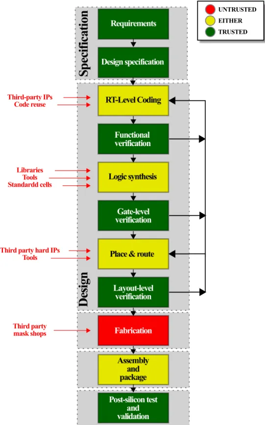
Any IC design phase is vulnerable to HT insertions whether the third-party suppliers of each phase are not fully certified. Figure 2.1, based on [24, 48, 61, 132], depicts a modern IC design flow adopted by most of the semiconductor companies and the level of trust in each step that might be a backdoor to an adversary insert a Trojan.
UNTRUSTED EITHER TRUSTED Third-party IPs Code reuse Libraries Tools Standardd cells
Third party hard IPs Tools
Third party mask shops
Fig. 2.1: Vulnerable steps of a modern IC production chain and their levels of trust taking into account: the adversary’s information about the design, the difficulty of tampering with the system, and the facility of detecting modifications [24, 48, 61, 132].
2.1 Trojan Insertion
identifying malicious adjustments or alterations. The whole specification phase is considered trusted since suspicious constraints are in the form of text and thus are easily debugged with-out any advanced test mechanism by the companies targeting to design a trusted IC. On the other hand, during the design phase, hardware description files (e.g. VHDL, VERILOG) may rely on the use of untrusted third-party IPs and codes, considerably compromising the design trustworthiness. The level of trust of logic synthesis, and place and route steps depends if the related libraries, tools, standard cells, and third-party hard IPs are properly certified. That is the reason that these phases are classified as either: trusted or untrusted. Even if adversaries have a limited access to the genuine design, only if all tools, libraries, and components were fully certified these steps would be considered trusted. In contrast, verification steps – typically per-formed in-house – are trusted if using testbenches and tools certified by qualified organizations. The same, however, is not applicable to the fabrication phase, normally executed within an out-house foundry, and thus considered the most sensitive phase of IC production chains. In fact, foundries, third-party mask shops, or their personnel have access to all genuine stream files (e.g. GDSII, OASIS), which might be used to predict system applications and tamper with genuine designs. Furthermore, even the phase of assembly and package might be untrusted assuming that adversaries may modify authentic hardware components during the chip integration or re-place them by malicious ones. However, unlike fabrication phase, obtaining the system design information during the assembly and package phase is a very challenging task, which consider-ably limits the possibility of attacks at this phase in relation to the fabrication one. Finally, the post-silicon test and validation phase could be trusted only if they are performed in-house or by a fully certified company. In the case where they are outsourced to an untrusted company, the test reports generated could be altered to mask possible effects caused by Trojans. Nevertheless, as this phase represents the last chance to detect Trojans before delivering the IC for deployment or costumers, it must be trusted.
2.1.1
Trojan Model
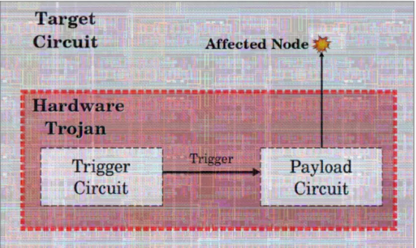
A Trojan model was defined in literature [24, 132] in which the HT is decomposed into two parts: the payload and the trigger. The payload is the part of the circuit that indeed causes harm-ful effects in the target circuit. The trigger is a monitoring circuit that serves as a mechanism to keep the payload inactive and thus hide the their effects until a rare condition is accomplished to activate it. Adversaries may use this clever strategy to make their HTs stealthy during the verification and validation steps. If the trigger is an always-on circuit, it is supposed to be less perceptible than the payload in order to reduce HT impacts in the original circuit and thus pre-vent its detection. On the other hand, as the payload remains most of the time inactivated, it can be a more sophisticated circuit. Thereby the HT model is basically a dormant circuit that, once triggered, modifies the targeted system original behavior. Fig. 2.2 depicts this HT model.
Fig. 2.2: Architecture of a Trojan inserted on a target circuit.
2.1.2
Trojan Taxonomy
In order to evaluate the risks of HTs, several studies have been reported taxonomies [24, 63, 79, 118, 120, 130, 131, 132, 132, 137] abstracting different categories related to the architecture, effects, and insertion of Trojans in ICs. Fig. 2.3 summarizes the existing Trojan insertion tax-onomies. A discussion about the different categories provided in the taxonomy of Fig. 2.3 is presented throughout this section.
Hardware Trojan Insertion
Insertion Phase Abstraction Level Activation
Mechanism Effect Location
Register-transfer Ph i l D l Internal Activation External Activation S P
2.1 Trojan Insertion
2.1.2.1 Insertion Phase
This category represents different phases of the IC design flow in which a possible adversary can be located. The following analysis presents the vulnerabilities to Trojan insertion in each phase.
• Specification: An adversary could intentionally define weak requirements for the sys-tem. As a possible result, design reliability may become compromised making the device vulnerable to leak sensitive information.
• Design: Even if the whole design is done in-house, the simple usage of untrusted tools, libraries, third-party IPs and standard cells may affect the it in a harmful way. For in-stance, untrusted tools may add extra circuitry in the system to introduce backdoors in the genuine design. If any step of the design phase is outsourced, a Trojan could be directly added to the hardware description files of the genuine circuit.
• Fabrication: An untrusted foundry, mask shop or their personal are able to retrieve the genuine circuit components and thus predict its behavior and probable applications. Therefore, the design becomes susceptible to addition or removal of components. Modi-fying physical circuits characteristics (sizes and channel doping concentration level) [72] can also fairly increase the circuit vulnerability to fault based attack.
• Assembly and package: The IC is encapsulated in a supporting case and the packaged chip is assembled in a PCB with other hardware. An adversary may add malicious hard-ware components surrounding the genuine design to provoke malfunctions or increase leakages.
• Post-silicon test: At testing phase, an adversary is no longer able to modify the genuine circuit structure, however the test set-up, programs or reports may be changed in order to mask possible Trojan effects. Besides that, as it is the last step of the IC design flow, it is the last opportunity to original designers to detect Trojans before the deployment phase.
2.1.2.2 Abstraction Level
The abstraction level refers to possible tampers with the design if an adversary has access to sensitive files at different abstraction levels. The following analysis presents HT insertion op-portunities in each abstraction level.
• System: A HT can simply be alterations in function specifications, protocols, interfaces and constraints of the genuine design. An adversary involved at the system level may add some obscure specifications to give him the control of secret data flowing through the manufactured device. For instance, an adversary at the specification phase could
change specifications of true random number generators (TRNG) to make it work in a predictable way due to some condition that only the owner of the HT is aware of. This is able to considerably reduce the reliability of secure systems based on these architectures and provide secret information to attackers.
• Development environment: Untrusted tools and scripts may present hidden functions, leading designers to generate circuits infected by Trojans. In addition, untrusted simula-tion tools and testbenches could mask HT effects. Any unreliable third-party vendor is able to insert Trojans at this level.
• Register-transfer: A HT can also be a simple modifications in genuine RT-level codes or constraint files. An adversary can modify circuit functions in order to provoke significant consequences such as failures in cryptographic blocks. Attackers at design phase or an untrusted code supplier are possible sources for the HT insertion at this level.
• Gate: The addition or removal of one or more gates in the original netlist is considered a gate-level HT. Standard delay format (sdf) files, that contains system timing data can also be modified, changing timing check, constraints, and delays to hide HT effects. Adver-saries at the gate design phase and third-party vendors have access to implement Trojans at this level.
• Transistor: Transistor addition can significantly increase leakages, opening backdoors for attackers to get knowledge about security-oriented circuit internal states. Moreover, transistors may be added to increase critical path delays, leading the circuit to malfunc-tion. Adversaries at design phase or untrusted tools, libraries and models are possible sources of Trojans at this level.
• Physical (layout): Original parameters of circuit components are vulnerable even after the layout generation. For instance, an attacker could alter original masks, changing tran-sistor lengths, widths or channel doping concentrations. Moreover, wires can be resized, generating malfunctions and extra leakages. Adversaries at design and fabrication level, or third-party mask shops have access to modify the original layout and insert such Tro-jans.
2.1.2.3 Activation Mechanism
If a Trojan is always activated, its effects in the circuit may upset some device property, making it exposed to verification and validation routines. However, if a HT remains dormant until the deployment phase, its disturbances in the circuit behavior become less noticeable, considerably hampering its detection. For this purpose, Trojans are likely to feature activation mechanisms used to activate them by a certain condition accomplished only after verification and validation
2.1 Trojan Insertion
phases. Therefore, HTs are considered dormant during test routines and hostile after being activated.
• Always on: The target circuit behavior is always affected by the HT. The Trojan is there-fore composed only by the payload.
• Internal activation: A Trojan is activated when a specific internal condition occurs in the circuit. For instance, an internal counter may trigger the HT if the clock exceeds a certain value. Besides that, internal signal patterns or rare conditions may trigger this type of Trojan.
• External activation: Trojans are activated by an attacker aware of the HT presence in the circuit. For instance, a Trojan may be designed to be activated whenever a certain value is set in the circuit inputs. Thus, attackers with the knowledge of such an activation mechanism are able to activate the HT. Sophisticated trigger mechanisms rely on very rare sequences, conditions or even side-channel attacks to be activated, making its detection almost impossible by users which are not aware of its activation mechanism.
2.1.2.4 Effect
A HT may lead the device to different effects by depending on the adversary possibilities and intentions. In the following analysis, a classification of the HT effects is presented in the sequel.
• Change function: Trojans change, add or remove original circuit functions. For instance, Trojans could lead to improper calculations under specific conditions, compromising the main system operations. For example, missile guidance systems may intentionally calcu-late a wrong target, leading the missile to strike a completely unintended destination. • Reduce reliability: An adversary can implement Trojans in a system for downgrading
its performance or rendering it more vulnerable to side-channel attacks. In other sys-tem applications, Trojans may increase the power consumption, causing a faster battery discharge to interrupt the circuit operation.
• Leak information: Trojans are designed to leak keys and plaintexts of cryptographic circuits by primary outputs or side-channel signals. An adversary could add a comparator Trojan that enables the key leakage whenever a certain input or sequence of outputs is set. • Denial of service (DoS): Trojans can make the circuit no longer able to work properly. For instance, a Trojan inserted in a military radar may lead it to not detect some specific threats.
2.1.2.5 Location
Trojans are also classified regarding to their location in the design. According to that, different kinds of attacks are possible.
• Processor: Trojan may add and remove instructions of processors, leading it to operate suspicious functions and cause malfunctions.
• Memory: Attackers with the control of memory elements may be able to get access to secret informations and clear sensitive data stored in the device.
• I/O: Pins be controlled by the HT may lead the circuit to avoid some specific conditions, output wrong signals and monitor communications.
• Power supply: Trojans in the power grid may control the device voltages and current, increasing leakages or causing failures.
• Clock: Trojans may alter circuit frequency or increase clock noise causing glitches and jitters. This threat can make secure blocks to leak information and create backdoors to side-channel attacks.
2.1.3
Case Studies: Trojans at Different Abstraction Levels
In this section, a few attacks using Trojans are presented in order to illustrate possible threats. In this regard, each Trojan presented in this section is accordingly classified to the taxonomy.
2.1.3.1 Trojan in an AES-128 [118, 120]
Authors of [118, 120] have developed a set of benchmarks, the Trust-Hub (http://www.trust-hub.org/), sponsored by the USA National Science Foundation (NSF). It is a source of bench-marks infected by different types of Trojans at diverse abstraction levels in order to support the security community to compare the behavior of Trojan-free and Trojan-infected circuits to evaluate HT detection methods. A set of benchmarks are available, considering different cate-gories in the Trojan taxonomy. In [120], a report about the available benchmarks is presented to encourage its application.
The AES-T2000 benchmark consists of a Trojan surrounding an AES-128 encrypting block with the purpose of leaking its secret key. This HT is triggered after detecting a sequence of 4 input plaintexts. The payload is responsible for generating a significant current leakage indicat-ing the actual state of each bit of the secret key. An attacker with access to the manufactured device can therefore exploit its current leakage to have access to the key. The code in the Fig. 2.4 illustrates this Trojan implementation. The library aes_128 is the original AES circuit, Trojan_Trigger and Trojan_Payload are respectively the trigger and the payload circuit.
2.1 Trojan Insertion
top.v – AES-128 with Trojan Trigger and Payload 1 module top(clk, rst, state, key, out); 2 input clk, rst;
3 input [127:0] state, key; 4 output [127:0] out;
5
6 aes_128 AES (clk, state, key, out);
7 Trojan_Trigger Trigger(clk, rst, state, Tj_Trig); 8 Trojan_Payload Payload (clk, rst, key, Tj_Trig); 9
10 endmodule
Fig. 2.4: Architecture of the Trojan-infected AES-T2000 benchmark [120].
The Trojan classification according to the Trojan taxonomy is: • Insertion phase: design
• Abstraction level: RT
• Activation mechanism: activated by a sequence of primary inputs • Effects: leak information
• Location: processor
2.1.3.2 Trojan in the Configuration Bitsream of FPGAs [26]
The HT in [26] illustrates an attack caused by an untrusted FPGA synthesis tool. The HT alters directly the FPGA configuration bitstream. To this goal, the cyclic redundancy check (CRC) used to verify the bitstream correct implementation is disable to mask the HT effects. Therefore, ROs are added in the circuit to perform redundant switching activity causing power
dissipation. Results in [26] show that the operating temperature is increased by over 160oC
without affecting the functionality of the original design. The consequences of such an attack drastically speed up the aging effects in the FPGAs.
The Trojan classification according to the Trojan taxonomy is: • Insertion phase: design
• Abstraction level: development environment • Activation mechanism: always-on
• Effects: reduce reliability, DoS • Location: any
2.1.3.3 Trojan in a Wishbone Interconnect Matrix [118, 120]
A gate-level implementation is illustrated by the benchmark wb_conmax-T100 from Trust-hub [118, 120]. It is composed by a Wishbone bus infected by a gate-level Trojan able to stuck at ’1’ the four most significant bits of the address bus of the first master, which determines its slave. In this particular example, the trigger is larger than the payload in order to impose a
very low activation probability about 9.78 × 10−68. The gate-level scheme of this Trojan design
is presented in the Fig. 2.5. Note that the original 4 most significant bits of the address bus are replaced by the Trojan affected Tj_address signals.
Original BUS
addr_i[31] addr_i[30] addr_i[29] addr_i[28]
Internal nodes Internal nodes
Fig. 2.5: Architecture of the gate-level Trojan implemented in the Wishbone bus in the bench-mark wb_conmax-T100 [118, 120].
The Trojan classification according to the Trojan taxonomy is: • Insertion phase: design
• Abstraction level: gate
• Activation mechanism: internally conditionally triggered • Effects: change Functionality, denial of Service
2.2 Trojan Detection
2.1.3.4 Parametric Trojans in Security Systems [17, 72]
Physical-level Trojans have been presented in literature as a dangerous backdoor for side-channel attacks. In [17], authors proposed an extremely stealthy approach for Trojan imple-mentation, only by modifying the doping area, polarity or concentration of a few transistors in the original design of Intel’s Random Number Generators (RNG). Using the same principle, authors in [72] perform key leakages in a PRINCE block cipher. Such Trojans alters the regular
threshold voltage (Vth) of a few inverters from the original design, only making them vulnerable
to VDDglitches. As only the owner of the Trojan is aware of this modification, the HT activation
is unlikely during regular tests. A possible type of layout modification is presented in Fig. 2.6 in order to illustrate the implementation of the dopant-level HT in which an adversary alters the channel doping concentration of a few gates of the genuine design.
Nwell (original) Nwell (Trojan) P-substrate VDD VSs in out P+ P+ N+ Nwell P-substrate VDD VSs in out
Trojan-infected inverter
Genuine inverter
Fig. 2.6: Layout of an inverter with the dopant Trojan presented in [72].
The Trojan classification according to the Trojan taxonomy is: • Insertion phase: fabrication
• Abstraction level: physical (layout)
• Activation mechanism: externally triggered (side-channel attack) • Effects: leak cryptographic keys, reduction of reliability
• Location: processor
2.2
Trojan Detection
For ensuring the IC trustworthiness, different techniques can be implemented to detect or pre-vent Trojans according to the level of trust in each phase of the IC design. Several stud-ies [48, 64, 69, 94, 130, 132] have reported comprehensible surveys about most detection meth-ods presented in literature, classifying them in accordance with their approaches.
The techniques basically evaluate the deviations caused by HTs on the system behavior or look for possible HT profiles. To this aim, the designers must be aware of at least a single specific parameter from the genuine device or define a target HT model to be detected. If the deviation produced in the evaluated parameter of a design under Trojan test (DUTT) is greater than an acceptable margin, the DUTT is classified as Trojan infected. In Fig. 2.7, a scheme based on prior surveys and works presents the main categories of testing techniques for detection of Trojans.
Among the categories of Trojan detection listed in Fig. 2.7, the destructive techniques re-quire reverse engineering of the genuine design in order to physically inspect the HT insertion. Otherwise, the non-destructive techniques are divided into: (1) post-silicon testing techniques that rely on detecting Trojans before the deployment of the device; and (2) run-time monitoring techniques that consist in on-line mechanisms able to detect and indicate – during the normal IC operation – malicious activities or malfunctions caused by Trojans. The content of Fig. 2.7 and the existing detection techniques are the theme of this section.
Hardware Trojan Detection Techniques EM Functional Testing Combined Hybrid
Destructive Non Destructive
Delay Transient Current Quiescent Current Run-time Monitoring
2.2 Trojan Detection
2.2.1
Destructive: Physical Inspection
A brute-force strategy for Trojan detection after fabrication is reverse-engineering the manufac-tured DUTT in order to recover its layout and look for discrepancies in relation to the original trusted one. This approach is possible thanks to high precision optical and scanning electron microscopes (SEM) after chemical mechanical polishing (CMP). In [18], it is shown the pos-sibility of detecting HTs with only a top-layer image in the CMOS 130 nm technology if the placement or the routing have been redone by the foundry. The image cross-correlation calcula-tions are applied to extract discrepancies between the original and the DUTT layouts. However, problems such as image noise, size and layer-level of Trojan modification make the detection considerably challenging. A SEM-based method was performed in [34] to detect Trojans in the same technology. In [152], filler cells are designed to be highly reflective at near-infrared wavelengths in order to produce easily measured watermarks of the genuine layout.
Despite presenting reliable results, these techniques feature some drawbacks such as being expensive, time-consuming, destructive, and difficult to be integrated into the regular testing phases. Moreover, to validate the manufactured lot of a particular IC, it would be necessary to sample at a least a few DUTTs to test it. Hence, even though a DUTT is stated as Trojan-free, it cannot be deployed after the physical inspection. Due to such inconveniences, the electric tests are more suitable, even if optical inspection offers accurate results. Besides that, as far as the technology nodes become smaller, the gates and connections in an IC will be more dense and compact, making this approach more and more difficult in a near future [48]. On the other hand, the approach is certainly applicable to certify a sample DUTTs as Trojan-free ICs (i.e. golden ICs), providing a set of fingerprints that are indeed referential data collected before the physical inspection alters the chips. The data from genuine ICs can be used afterwards to be statistically compared with results from the DUTT, allowing to classify it as infected or not.
2.2.2
Functional (Logic) Testing
Functional or logic testing techniques are originated from regular verification and validation phases. Its operation consists in evaluating the behavior of primary outputs and internal nodes of circuit given a set of input vectors. If the DUTT presents suspicious deviations or properties, the design is assumed to be Trojan infected. Functional tests can therefore be performed to detect Trojans at any step of the IC design.
There are different approaches addressing functional testing. A common approach is defin-ing and identifydefin-ing possible suspicious nets in the netlist. The authors in [19] proposed a method for finding weakly correlated signals or isolated sections in the netlist to find possible HT trig-gers. In [107], the authors compare Trojans in the literature in order to define architectural patterns frequently used in HT designs. Thereafter, they implement a score-based classifica-tion method to detect Trojans in untrusted netlists. Both methods are able to detect gate-level
Trojans in non certified netlist based on their assumptions about the Trojan model.
The studies [15, 30, 117], propose detecting suspicious activities caused by Trojans in third party IPs. In addition, if a complete trusted specification is available, a high-level golden model can be generated to perform a formal verification method such as sequential equivalence check-ing (SEC) to identify a possible HT. However, without havcheck-ing any trusted specification of the design, it is consider as a black box, rendering the HT detection quite challenging.
Techniques like in [25, 65] are able to detect Trojans implemented in different levels by applying data vectors at DUTT primary inputs with the intention of stimulating the HT activa-tion and checking possible modificaactiva-tions at DUTT primary outputs caused by active Trojans. In [40, 78, 119], the authors presented test generation strategies to optimize the number of test vectors needed to activate a Trojan.
Furthermore, other approaches such as the one presented in [27] are implemented to maxi-mize the probability of triggering Trojans by inputing test pattern based on multiple excitation of rare logic conditions. This method allows the reduction of the number of required test vec-tors compared to a weighted random pattern. With the activation of the HT, the effectiveness of functional tests for its detection is fairly enhanced.
2.2.3
Side-Channel Analysis
Another approach used to detect hardware Trojans is side-channel analysis [10]. These tech-niques are based on the fact that Trojans, even inactivated, cause leakages in terms of power, delays and EM emissions [132]. If a golden model is available, the Trojan detection is per-formed by comparing the side-channel traces from certified Trojan-free devices (golden ICs) and DUTTs.
In side-channel analysis, security designers have to deal with two main challenges: (1) the process (PV) and environment variations – which possibly masks Trojan effects in the side-channel signals–, and (2) the need for a golden model. The effects of PV basically results in an
alteration of circuit parameters such as threshold voltages (Vth), channel lengths (L), and oxide
thickness (Tox). For instance, Vthcan approximately fluctuate 20% among its original value in
modern technologies [33]. Thus, ultra-small Trojans – sized on the order of 100 to 10000 times smaller than the original circuit dimensions – would naturally be masked by PV. Therefore, design and test efforts must be considered in order to reduce or compensate the PV effects. Each method proposes different strategies with this purpose. The need for a golden model is overcome by collecting signatures from golden ICs obtained from devices certified by physical inspection or certificated fabrication process. Furthermore, the methodology in [83] shows that is possible to generate fingerprints only based on trusted simulation models and measurements from process control monitor, without requiring certified ICs.
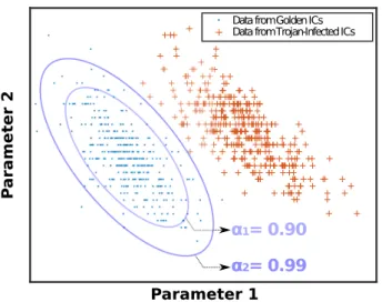
An illustrative example of the detection procedure is presented in Fig. 2.8. A certain input vector is applied in the primary inputs of a set of golden ICs and thus, the side-channel signals
2.2 Trojan Detection
are collected to produce a golden signature in a space of parameters. The same test procedure is performed in each DUTT, producing data to be compared with this golden signature. In Fig. 2.8, the golden data are used to generate error ellipses surrounding it considering a different
significance levels (α1 and α2). Thereby, if the data obtained from a certain DUTT is outside
this ellipse, this device is classified as Trojan-infected with the significance level previously considered to generate the error ellipse.
P
ara
meter 2
Parameter 1
Data from Golden ICs Data from Trojan -Infected ICs
1= 0.90
2= 0.99
Fig. 2.8: Space of parameters generated by the data obtained from golden devices – error
ellipses with difference significance levels α1 = 0.90 and α2 = 0.99 surround it –, and from
Trojan-infected DUTTs.
The HT detection problem is defined in terms of a statistical hypothesis testing: (
H0 : The DUTT is Trojan-free
H1 : The DUTT is Trojan-infected,
in which the detection is performed whenever the null hypothesis H0 is rejected. For the
illus-trative test of Fig. 2.8, the region of acceptance of the null hypothesis H0is given by the ellipses,
generated according to a significance level αi. A specific data outside this ellipse has the
prob-ability 1 − α to reject H0 and therefore accept H1. Moreover, if the data is obtained from a set
of known Trojan-infected DUTTs, the total number of points outside the ellipse normalized by the total of tests denotes the true negative rate (or the detection rate) which is the number of well-succeed detections. In addition, the total amount of data generated from Trojan-infected devices located inside the ellipse normalized by the total number of events denotes the false
negative rate (FN), also refereed to in literature as false alarms. The relation between the false
negative rate FN and the detection rate DRis given by Eq. 2.1.
2.2.3.1 Parameters
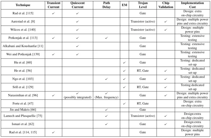
Different side-channel signals such as transient current (IDDT) [10], quiescent current (IDDQ) [8],
path delay [66] and EM [60] traces are used to generate signatures from golden devices and DUTTs. Besides that, combination of intrinsically related parameters were also proposed as a solution to compensate PV effects [96]. In the following analysis, different methods using these parameters are presented and discussed.
• Transient Current (IDDT): As HT circuitries share the same power supply with the target
system, traces obtained from the power supply pins can track possible alterations caused by a Trojan by evaluating the generated current trace. For this purpose, the switching activity in the circuit is used to gain information about the amount and the type of gates consuming dynamic power. The first Trojan detection method using side-channel analy-sis [10] used indeed the power trace generated by the transient current to gather a set of fingerprints of Trojan-free and Trojan-infected DUTTs. In this study, a Karhunen–Loève (KL) expansion is used to eliminate the measurement noise and therefore perform the detection. Alternatively, further studies have also addressed detecting Trojans even in the presence of PV. The approaches presented in [114, 115, 136] rely on measuring multiple power ports or pads individually in order to isolate the Trojan effects to a specific chip location and thus increase its relative impact. In [136], the strategy was integrate the total
current from a specific pad, while in [114, 115], similar methodologies used the IDDT
provided by each power port (see Fig. 2.9) as parameters to generate scatter plots PPxxvs.
PPyy.
P
P
01P
P
12PP
25PP
58Fig. 2.9: Chip partition approach based on the measurement of multiple power supply pins for Trojan isolation [114, 115].
2.2 Trojan Detection
In [20], an on-chip current sensing structure combined with a power gating architecture is used to isolate Trojans and produce digital results carried out by a scan chain. Silicon demonstrations of Trojans design and detection in wireless cryptographic ICs are shown in [84]. In this work, authors present an always-on Trojan able to leak keys of a 128-bits AES core and detect it by measuring the transmission power obtained in different inputs.
• Quiescent Current (IDDQ): Quiescent current leakage adds by a HT is another
trace-able parameter to identify it, even in scenarios where there is no switching activity in any
Trojan nets. In [8, 140], the authors demonstrated the effectiveness of analyzing IDDQs
measured simultaneously from multiple locations of the chip. A test structure is used in order to emulate the Trojans in different positions in the circuit and perform its detection by measuring multiple power ports. Despite requiring distinct input vectors, test
proce-dures for obtaining IDDQare very similar to the ones used in IDDT. Most of the proposed
methods using IDDQconsider it as an auxiliary signal in multiple parameter analysis.
• Path Delay: Another consequent effect of a HT infection is the delay addition encoun-tered in specific nodes of the original circuit. A Trojan inserted between two blocks modifies the authentic datapath and thus increases a delay in such nets. In another pos-sible implementation, it is directly connected to an original node of the circuit –without necessarily cutting lines of device’s nets– enhancing the fan-out and capacitive loads of the previous gate and therefore, increasing the path delay.
Measuring path delays in sequential circuits after fabrication, however is not a simple task. If no extra on-chip circuitry is used for this purpose, it is only possible to measure path delays which originates from primary inputs and terminate at primary outputs. Be-sides that, as in synchronous circuits the clock controls the data flow from stage-to-stage, it is not possible to measure the delay of each stage. For this reason, extra on-chip cir-cuits such as full-scans must be used to enable the measurement of these delays during post-silicon testing phase. Indeed, Trojan detection techniques based on path delay rely on using mechanisms able to output variables indicating the path delay. In [80], a de-lay characterization is done by a secondary clock signal controlling shadow registers. In Fig. 2.10, a diagram shows the architecture used in this work. The original clock (clk1) drives the regular registers, a secondary clock (clk2) controls a shadow register –used specifically for detection of Trojans– and the outputs of both are connected to a compara-tor. The test procedure is basically retarding gradually the clk2 in relation to clk1 until the comparator indicates that outputs from registers are different. At this time, the skew between clk1 and clk2 denote the delay of this combinational path. The same test proce-dure must be repeated for each pipeline stage of the circuit in order to characterize path delays of the whole circuit.
Result Bit Main Circuit clk1 clk2 Source
Register DestinationRegister
Comparator
Shadow Register Combinational
Path
Fig. 2.10: Delay characterization with negative-skewed shadow registers [80].
comparator outputs as chip authentication [81]. In [21], authors proposed selecting more vulnerable paths to and input vectors to activate them. Moreover, other techniques used embedded test structures for on-chip measurements of path delays [62, 74, 75] while in [36] a framework based on self-authentication is proposed. In [66], an effective manner to gather the fingerprint of all path delays is proposed while a more recent approach [146] uses latch-structures to compare relative delays of different paths in the circuit to identify discrepancies.
• EM Emissions: Switching activity in Trojans nets is a source of unsuspected EM emis-sions. Non-invasive techniques are therefore used to track DUTT emissions and compare them with a golden model. Prior studies [14, 129] use similar approaches to detect Tro-jans inserted in different locations in FPGAs. The analysis consists in scanning the whole circuit with an EM probe able to collect data from different spots of the circuit. Once collected, the golden and DUTT data are compared in order to generate a map depicting the obtained differences between them. In addition, the technique in [60] uses a thermal map with the same purpose. In Fig. 2.11, an illustrative map presents how results are generated considering different Trojan locations. Each pixel of the EM map represents a specific spot in the circuit and its color the difference between DUTT and golden device. Recently, [56] reported another methodology able to detect Trojans using EM emissions without the need of neither a golden IC nor the netlist. In their study, RT-level simula-tions generate patterns to be compared with the ones obtained from FPGA to perform the detection of activated Trojans.
• Combined Parameters: Another efficient approach consists in combining signatures obtained from different side-channels and thus, increasing the amount of obtained data to enhance the Trojan detection effectiveness. Moreover, the intrinsic relation between
2.2 Trojan Detection
(a) (b)
Fig. 2.11: EM emission maps generated considering a Trojan free DUTT (a); and a Trojan-infected DUTT (b). For each pixel, blue shades represents low difference between EM emission from golden device and DUTT, and red shades denotes considerable discrepancies [14, 129].
different side-channel signals is a clever strategy to compensate PV effects [147]. For instance, if PV acts increasing the power consumption of a specific logic-gate, its con-sequent effect is reducing its path delay. Thus, the value of the power consumption of a given gate allows predicting its path delay in this PV environment. Authors in [96] take advantage of it to propose a detection technique considering transient current and path delay (obtained indirectly by the maximum operation frequency). In [59], the relation between transient and quiescent current are used while in [103], the technique uses delay and electromagnetic measurements to detect Trojans. An unified framework is proposed in [70] providing detection results for all side-channel signals and thereafter combining them.
2.2.3.2 Implementation Cost
As presented in the previous sections, side-channel analysis detection techniques require strate-gies with considerable efforts in terms of design and test to compensate PV effects. The most used design-level approach consists of splitting the original circuit in several measurement do-mains in order to isolate the Trojan impacts to a specific domain [8, 21, 136]. These strategies necessarily require extra on-chip circuitry or multiple pads to separate the subcircuits signals and additional post-manufacture tests and dedicated test set-ups to generate all needed signa-tures, thus increasing the project cost.
Most of path delay based methods uses a secondary clock signal to control a set of shadow registers. Similarly, most of current based methods require measuring the signals from multiple power supply pins in order to isolate the Trojan and applying power gating to enhance the detection rate. Moreover, even if EM-based methodologies does not require necessarily extra hardware in the original design, high resolution devices to analyze EM or thermal maps are
needed, increasing time-to-market and set-up cost of testing phase, besides the challenging procedures for nanoscale technology nodes.
2.2.4
Run-time Monitoring
Logic and side-channel signals are evaluated by run-time monitoring structures embedded in the original design. In this case, if a Trojan is activated after the deployment phase, the monitoring system is able to generate a flag indicating a Trojan alert. In [35, 39], techniques treat inter-ferences in circuit functionalities caused by activated Trojans as fault-models and thus detect it. Furthermore, the technique presented in [47] relies on monitoring the temperature of the circuit. Extra power consumption caused by a Trojan causes a discrepancy between the expected and the measured temperature, making the method able to detect Trojan-infected circuits.
2.2.5
Combined and Hybrid Methods
In order to combine benefits from side-channel analysis, functional testing, or run-time mon-itoring, authors have proposed mixed techniques able to detect Trojans by several means. In this subsection two main combined methods – Ring Oscillator and Gate-Level Characterization (GLC) – are presented.
2.2.5.1 Ring Oscillator
Detection techniques presented in [58, 67, 76, 149] propose the implementation of a set of RO distributed over the original layout. If a HT is inserted close to one of the RO that composes the
network, the VDD drop caused by the Trojan slightly reduces the RO supply current, therefore
modifying its frequency. By analyzing this deviation, designers are able to track Trojans. This method combines the leakage current and the functional behavior of ROs, making it able to detect even inactive Trojans. Fig. 2.12 illustrate the basic implementation of RO based methods. Besides that, while ROs keep running after IC deployment, this method can also be used as a run-time monitoring, increasing its efficacy if the Trojan is activated. In a context in which the adversary knows this HT detection method, he is able to simply change the size of the gates that composes the RO, leading it to run in the same expected frequency. Nevertheless, this cat-and-mouse game action increases the supply current, making the HT detection by other side-channel analysis method more likely, forcing the adversary to improve even more his attack.
2.2.5.2 Gate-Level Characterization (GLC)
In [113], GLC were firstly proposed for detecting Trojans with the support of a trusted netlist. The method is based on characterizing the side-channel signals of all gates from a specific
2.2 Trojan Detection
Fig. 2.12: A basic RON structure [149] with 8 ROs distributed in the circuit layout.
segment of the manufactured device. The technique is basically solving the linear equation 2.2 to find the PV scaling factor of each gate.
n X j=1 αj Ik,jnom = ˆI total k (2.2)
where αj is the PV scaling factor and Ik,jnom is the nominal leakage power for the gate j
given an input vector k, and ˆI total
k is the total measured leakage power for the k-th input vector.
By having a number of input vectors larger than the count of all gates in the circuit segment under test, it is possible to solve the system of equations stated in 2.2. Their solutions are combined in order to statically estimate bounds for the calculated scaling factors. Basically, if
the results of αj diverge to different values as far as the number of tests increases, the nominal
model does not represent the manufactured DUTT and thus, it is classified as Trojan infected. Other methods were proposed using the same GLC principle. In [138] authors propose using thermal control process to characterize the PV scaling factors for all gates while in [139], the same authors propose overlapping circuit segments in order to find inconsistencies between the obtained results, indicating the presence of a Trojan. A similar approach for inconsistency-based characterization was proposed in [11] considering the quiescent current as side-channel signal
![Fig. 2.5: Architecture of the gate-level Trojan implemented in the Wishbone bus in the bench- bench-mark wb_conmax-T100 [118, 120].](https://thumb-eu.123doks.com/thumbv2/123doknet/14598712.730883/33.893.172.720.361.751/architecture-level-trojan-implemented-wishbone-bench-bench-conmax.webp)
![Fig. 2.6: Layout of an inverter with the dopant Trojan presented in [72].](https://thumb-eu.123doks.com/thumbv2/123doknet/14598712.730883/34.893.113.781.495.635/fig-layout-inverter-dopant-trojan-presented.webp)
![Fig. 2.7: Classification of hardware Trojan detection techniques [48, 64, 69, 94, 130, 132].](https://thumb-eu.123doks.com/thumbv2/123doknet/14598712.730883/35.893.171.721.540.1030/fig-classification-hardware-trojan-detection-techniques.webp)
![Fig. 2.9: Chip partition approach based on the measurement of multiple power supply pins for Trojan isolation [114, 115].](https://thumb-eu.123doks.com/thumbv2/123doknet/14598712.730883/39.893.270.607.721.1059/chip-partition-approach-measurement-multiple-supply-trojan-isolation.webp)
![Fig. 2.10: Delay characterization with negative-skewed shadow registers [80].](https://thumb-eu.123doks.com/thumbv2/123doknet/14598712.730883/41.893.203.686.109.379/fig-delay-characterization-negative-skewed-shadow-registers.webp)
![Fig. 2.12: A basic RON structure [149] with 8 ROs distributed in the circuit layout.](https://thumb-eu.123doks.com/thumbv2/123doknet/14598712.730883/44.893.257.668.126.565/fig-basic-ron-structure-ros-distributed-circuit-layout.webp)