HAL Id: hal-00141149
https://hal.archives-ouvertes.fr/hal-00141149
Submitted on 11 Apr 2007
HAL is a multi-disciplinary open access archive for the deposit and dissemination of sci-entific research documents, whether they are pub-lished or not. The documents may come from teaching and research institutions in France or abroad, or from public or private research centers.
L’archive ouverte pluridisciplinaire HAL, est destinée au dépôt et à la diffusion de documents scientifiques de niveau recherche, publiés ou non, émanant des établissements d’enseignement et de recherche français ou étrangers, des laboratoires publics ou privés.
Dephasing due to a fluctuating fractional quantum Hall
edge current
T.K.T. Nguyen, Adeline Crépieux, Thibaut Jonckheere, A.V. Nguyen, Y.
Levinson, T. Martin
To cite this version:
T.K.T. Nguyen, Adeline Crépieux, Thibaut Jonckheere, A.V. Nguyen, Y. Levinson, et al.. Dephasing due to a fluctuating fractional quantum Hall edge current. Proceedings des 6èmes Rencontres du Vietnam, Aug 2006, Hanoi, Vietnam. �hal-00141149�
DEPHASING DUE TO A FLUCTUATING FRACTIONAL QUANTUM HALL EDGE CURRENT
T. K. T. NGUYEN1,2, A. CR´EPIEUX1, T. JONCKHEERE1, A. V. NGUYEN2, Y. LEVINSON3,
AND T. MARTIN1
1
Centre de Physique Th´eorique, CNRS Luminy case 907, 13288 Marseille cedex 9, France
2
Institute of Physics and Electronics, 10 Dao Tan, Cong Vi, Ba Dinh, Hanoi, Vietnam
3
Department of Condensed Matter Physics, The Weizmann Institute of Science, Rehovot 76100, Israel
The dephasing rate of an electron level in a quantum dot, placed next to a fluctuating edge current in the fractional quantum Hall effect, is considered. Using perturbation theory, we first show that this rate has an anomalous dependence on the bias voltage applied to the neighboring quantum point contact, because of the Luttinger liquid physics which describes the fractional Hall fluid. Next, we describe exactly the weak to strong backscattering crossover using the Bethe-Ansatz solution.
1 Introduction
The presence of electrical environment influences the transport through a quantum dot: its energy level acquires a finite linewidth if the environment has strong charge fluctuations. Several experiments, performed with a quantum dot embedded in an Aharonov-Bohm loop, probed the phase coherence of transport when the dot is coupled to a controlled environment, such as a quantum point contact (QPC)1. Charge fluctuations in the QPC create a fluctuating potential
at the dot, modulate its electron level, and destroy the coherence of the transmission through the dot2. Theoretical studies for describing this dephasing have been developped3,4, and were applied to a quantum Hall geometry5, and to a normal metal-superconductor QPC6.
In this work, we consider the case of dephasing from a QPC in the fractional quantum Hall effect (FQHE) regime7. QPC transmission can be described by tunneling between edge states which represent collective excitations of the quantum Hall fluid. It is interesting because the transport properties deviate strongly from the case of normal conductors8,9,10: for the weak
backscattering (BS) case, the current at zero temperature may increase when the voltage bias is lowered, while in the strong BS case, the I(V ) is highly non linear. It is thus important to address the issue of dephasing from a Luttinger liquid.
2 Dephasing in the fractional quantum Hall regime
The system we consider is depicted in Fig. 1. The single level Hamiltonian for the dot reads HQD = ²0c†c, where c† creates an electron. This dot is coupled capacitively to a point contact
in the FQHE. The Hamiltonian which describes the edge modes in the absence of tunneling is: H0= (¯hvF/4π)R dx[(∂xφ1)2+ (∂xφ2)2], where φ1 and φ2 are the chiral Luttinger bosonic fields,
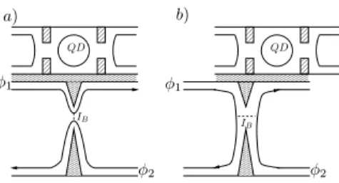
✁✁✁✁✁✁✁✁✁✁✁✁✁✁ ✁✁✁✁✁✁✁✁✁✁✁✁✁✁ ✁✁✁✁✁✁✁✁✁✁✁✁✁✁ ✂✁✂✁✂✁✂✁✂✁✂✁✂✁✂✁✂✁✂✁✂✁✂✁✂✁✂✁✂ ✂✁✂✁✂✁✂✁✂✁✂✁✂✁✂✁✂✁✂✁✂✁✂✁✂✁✂✁✂ ✂✁✂✁✂✁✂✁✂✁✂✁✂✁✂✁✂✁✂✁✂✁✂✁✂✁✂✁✂ ✄✁✄✁✄✁✄✁✄✁✄✁✄✁✄✁✄✁✄✁✄✁✄ ✄✁✄✁✄✁✄✁✄✁✄✁✄✁✄✁✄✁✄✁✄✁✄ ✄✁✄✁✄✁✄✁✄✁✄✁✄✁✄✁✄✁✄✁✄✁✄ ☎✁☎✁☎✁☎✁☎✁☎✁☎✁☎✁☎✁☎✁☎✁☎ ☎✁☎✁☎✁☎✁☎✁☎✁☎✁☎✁☎✁☎✁☎✁☎ ☎✁☎✁☎✁☎✁☎✁☎✁☎✁☎✁☎✁☎✁☎✁☎ ✆ ✆ ✝ ✝ ✞ ✞ ✟ ✟ ✠ ✠ ✡ ✡ ☛ ☛ ☞ ☞ ✌ ✌ ✍ ✍ ✎ ✎ ✏ ✏ ✑✁✑ ✑✁✑✒ ✒ ✓✁✓ ✓✁✓✔ ✔ ✕✁✕✁✕ ✕✁✕✁✕ ✕✁✕✁✕ ✕✁✕✁✕ ✕✁✕✁✕ ✕✁✕✁✕ ✕✁✕✁✕ ✕✁✕✁✕ ✕✁✕✁✕ ✕✁✕✁✕ ✕✁✕✁✕ ✕✁✕✁✕ ✖✁✖✁✖ ✖✁✖✁✖ ✖✁✖✁✖ ✖✁✖✁✖ ✖✁✖✁✖ ✖✁✖✁✖ ✖✁✖✁✖ ✖✁✖✁✖ ✖✁✖✁✖ ✖✁✖✁✖ ✖✁✖✁✖ ✖✁✖✁✖ ✗✁✗✁✗ ✗✁✗✁✗ ✗✁✗✁✗ ✗✁✗✁✗ ✗✁✗✁✗ ✗✁✗✁✗ ✘✁✘✁✘ ✘✁✘✁✘ ✘✁✘✁✘ ✘✁✘✁✘ ✘✁✘✁✘ ✘✁✘✁✘ ✙✁✙✁✙ ✙✁✙✁✙ ✙✁✙✁✙ ✙✁✙✁✙ ✙✁✙✁✙ ✙✁✙✁✙ ✚✁✚✁✚ ✚✁✚✁✚ ✚✁✚✁✚ ✚✁✚✁✚ ✚✁✚✁✚ ✚✁✚✁✚ ✛✁✛✁✛ ✛✁✛✁✛ ✛✁✛✁✛ ✛✁✛✁✛ ✛✁✛✁✛ ✛✁✛✁✛ ✛✁✛✁✛ ✛✁✛✁✛ ✛✁✛✁✛ ✛✁✛✁✛ ✛✁✛✁✛ ✛✁✛✁✛ ✜✁✜✁✜ ✜✁✜✁✜ ✜✁✜✁✜ ✜✁✜✁✜ ✜✁✜✁✜ ✜✁✜✁✜ ✜✁✜✁✜ ✜✁✜✁✜ ✜✁✜✁✜ ✜✁✜✁✜ ✜✁✜✁✜ ✜✁✜✁✜ QD QD φ2 φ2 φ1 φ1 IB I B a) b)
Figure 1: Schematic description of the setup: the quantum dot (top) is coupled capacitively to a quantum point contact in the FQHE regime: a) case of weak backscattering, b) case of strong backscattering.
By varying the gate potential of the QPC, one can switch from a weak BS situation, where the Hall liquid remains in one piece (Fig. 1a), to a strong BS situation where the Hall liquid is split in two (Fig. 1b). In the former case, the entities which tunnel are edge quasiparticle excitations. In the latter case, between the two fluids, only electrons can tunnel. We consider the weak BS case, and then we use a duality transformation8,11 to describe the strong BS case. The tunneling Hamiltonian between edges 1 and 2 reads Ht = Γ0eiω0tψ2+(0)ψ1(0) + h.c. where
we have used a Peierls substitution to include the voltage: ω0 = e⋆V /¯h (e⋆= νe is the effective
charge, ν is the filling factor). The quasiparticle operator is ψi(x) = ei √νφ
i(x)/√2πα (the spatial
cutoff is α = vFτ0, with τ0 the temporal cutoff).
The Hamiltonian describing the interaction between the dot and the QPC reads Hint =
c+cR
dxf (x)ρ1(x), with f (x) a Coulomb interaction kernel, which is assumed to include screening
by the nearby gates f (x) ≃ e2e−|x|/λs/√x2+ d2, where d is the distance from the dot to the
edge, λs is a screening length. The dephasing rate, expressed in terms of irreducible charge
fluctuations in the adjacent wire, is written as3,4,5: τϕ−1 = 1 4¯h2 Z ∞ −∞ dt Z dxf (x) Z dx′f (x′)hhρ1(x, t)ρ1(x′, 0) + ρ1(x′, 0)ρ1(x, t)ii . (1)
The equilibrium contribution to the dephasing rate corresponds to the zero order in the tunneling amplitude Γ0: (τϕ−1)(0) = ν 4π2¯h2 Z ∞ −∞dt Z dxf (x) Z dx′f (x′)X η=± ∂xx2 ′Gη−η1 (x − x′, t) , (2)
where the bosonic Green’s function is Gη1η2
i (x − x′, t1− t2) = hφi(x, t1η1)φi(x′, tη22) − φ2ii. The
coefficients η,η1,2 = ± identify the upper/lower branch of the Keldysh contour. There is no
contribution to first order in the tunneling Hamiltonian, while the non-equilibrium contribution corresponding to the second order in Γ0 exists:
(τϕ−1)(2) = − ν 4π2¯h4 Γ2 0 2(2πα)2 Z ∞ −∞ dt Z dxf (x) Z dx′f (x′) X η,η1,η2,² η1η2 Z ∞ −∞ dt1 Z ∞ −∞ dt2 ×ei²ω0(t1−t2)eνGη1η22 (0,t1−t2)eνGη1η21 (0,t1−t2)n∂2 xx′Gη−η1 (x − x′, t) + ν[∂xGηη1 1(x, t − t1) − ∂xGηη1 2(x, t − t2)][∂x′G−ηη 1 1 (x′, −t1) − ∂x′G−ηη 2 1 (x′, −t2)] o . (3) The dephasing rate depends on the geometry of the set up via the length scales d, λs, and
α. The assumption of strong screening λs ∼ α = vFτ0 is made (f (x) ≃ 2e2αδ(x)/d). Inserting
Gηη1 ′(x, t) = − lnnsinh[π[(x/vF−t)((η+η′)sgn(t)−(η−η′))/2+iτ0]/¯hβ]
.
sinh[iπτ0/¯hβ]
o
, where β = 1/kBT , in the dephasing rate gives: (τϕ−1)(0) = 4e4τ02ν/π¯h3βd2 and,
(τϕ−1)(2)= e 4Γ2 0 π2¯h4v2 Fd2 ν2τ2ν 0 Γ(2ν) µ2π ¯ hβ ¶2ν−1 cosh µω 0¯hβ 2 ¶ ¯ ¯ ¯ ¯ Γ µ ν + iω0¯hβ 2π ¶¯ ¯ ¯ ¯ 2 . (4)
Note that (τ−1
ϕ )(2) = (eτ0/d)2SI(0), with SI(0) = R dthhI(t)I(0)ii the zero-frequency BS
noise. The non-equilibrium contribution of the dephasing rate is proportional to the zero-frequency noise9,10,11,12 in the quantum Hall liquid. At zero temperature, the non-equilibrium dephasing rate given by Eq. (4) leads to (τ−1
ϕ )(2)∝ |ω0|2ν−1 and depends on the QPC bias with
the exponent 2ν − 1 < 0, in sharp contrast with the linear dependence obtained by Levinson3.
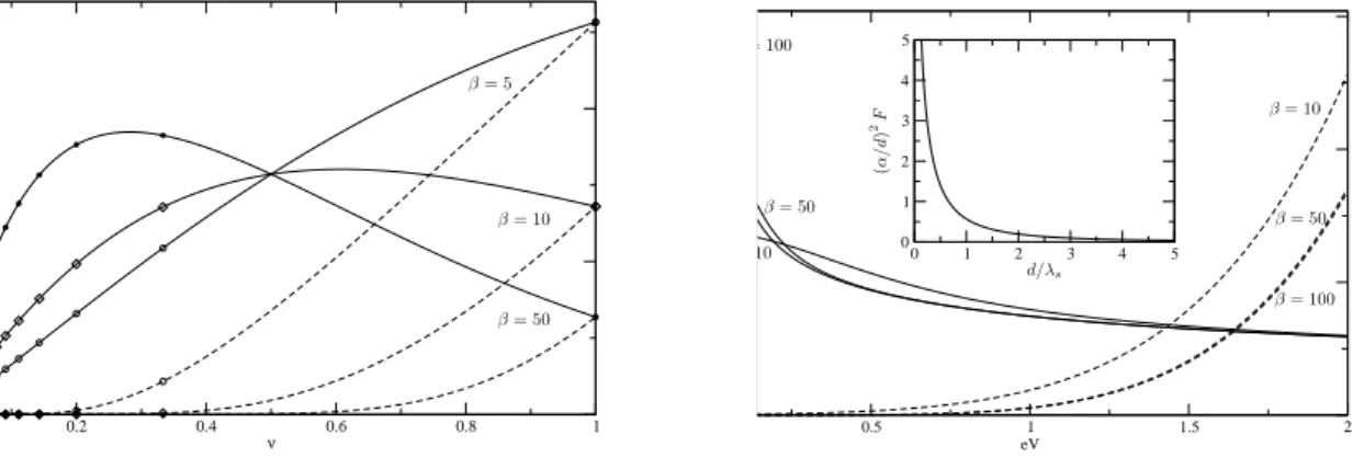
0.2 0.4 0.6 0.8 1 ν β = 10 β = 5 β = 50 0.5 1 1.5 2 eV 0 1 2 3 4 5 0 1 2 3 4 5 β = 10 10 β = 100 = 100 β = 50 β = 50 d/λs (α / d ) 2F
Figure 2: (Left) Dephasing rate, plotted in units of e4
Γ2 0τ0/π 2 ¯ h4 v2 Fd 2
, as a function of the filling factor for weak BS (full line) and strong BS (dashed line) at QPC bias eV = 0.1. The star, diamond and circle points correspond to the Laughlin fractions ν = 1/m, m odd integer. (Right) Dephasing rate as a function of QPC bias with ν = 1/3 for weak BS (full line) and strong BS (dashed line). The insert is the ratio of non-equilibrium contribution in dephasing rate between the arbitrary screening and strong screening multiplied by (α/d)2
as a function of d/λs.
In the left of Fig. 2, we plot the dependence of the non-equilibrium contribution of the dephasing rate on the filling factor ν for weak BS and strong BS for several temperatures (β = 5, 10, 50) at fixed QPC bias. ν is considered as a continuous variable, while it has physical meaning only at Laughlin fractions7. For the strong BS case, the dephasing rate increases when
the ν increases. For weak BS and 1/β ¿ eV , the dephasing rate has a local maximum at ν < 1/2, the position of which depends on temperature: when the temperature increases, it gets closer to ν = 1/2. The rate at ν = 1 is smaller than that at ν = 1/3. This result demonstrates that for two different filling factors, we can have comparable dephasing rates. For weak BS and 1/β > eV , the dephasing rate increases when the filling factor increases. In the right of Fig. 2, the dependence of the dephasing rate on the QPC bias voltage is plotted for ν = 1/3 and several temperatures. In the case of strong BS, the dephasing rate increases when the bias increases. For 1/β ¿ eV , the dephasing rate saturates, whereas for 1/β > eV , the dephasing rate increases when eV increases, but it increases from a finite value (not shown), which is proportional to the temperature. Things are quite different at weak BS. At high temperatures, the dephasing rate decreases when we increase eV : this behavior is symptomatic of current and noise characteristic in a Luttinger liquid. In the low temperature case 1/β ¿ eV , for small eV , the lower the temperature, the bigger the dephasing rate and the faster it decreases when we increase eV . 3 General formula for the decoherence rate
The charge fluctuations are directly related to the current fluctuations along the edges which are identical to the fluctuations of the tunneling current. The tunneling current fluctuations were computed non pertubatively using Bethe-Ansatz techniques13. We can therefore invoke current
conservation at the point contact to derive a general formula for the decoherence rate, which describes the crossover from weak to strong BS: (τϕ−1)(2) = (e3τ02/d2)(V Gdif f−I)ν/(1−ν) where
Gdif f = ∂VI is the differential conductance and I is the current14. This expression allows us to
Remarkably, it is possible to go beyond the strong screening limit, and one can compute Eq. (3) for an arbitrary Coulomb kernel f (x). The result can be displayed in terms of the ratio between the arbitrary screening dephasing rate and the strong screening dephasing rate:
F ≡ (τ −1 ϕ )(2) (τϕ−1)(2)λs→α = d 2 (eα)2 ·Z ∞ 0 dxf (x) ¸2 . (5)
If the Coulomb interaction kernel f (x) is chosen as suggested before, the dephasing rate at arbitrary λshas an analytical expression: F = (πd/2α)2[E0(d/λs) + N0(d/λs)], where E0(d/λs)
and N0(d/λs) are the Weber and the Neumann functions of zero order. F is plotted in the
insert of Fig. 2: F is infinite in the absence of screening. However, the presence of metallic gates always imposes a finite screening length. F decreases with d/λs and approaches 1 when λs is
close to the spatial cutoff α. The dephasing rate increases when the screening decreases.
4 Conclusion
We have established a general formula for the dephasing rate of a quantum dot located in the proximity of a fluctuating fractional edge current. For strong screening, we have shown that the dephasing rate is given by the tunneling current noise, for both weak and strong BS. For weaker screening, the spatial dependence of the density-density correlation function has to be taken into account, but we have shown explicitly that the long range nature of the Coulomb interaction can be included as a trivial multiplicative factor. The fact that the dephasing rate decreases with increasing voltage can be reconciled with the fact that the charge noise is directly related to the BS current noise in the FQHE. There it is known, and seen experimentally, that when the bias voltage dominates over the temperature, both the tunneling current and noise bear a power law dependence ∼ V2ν−1 with a negative exponent. The fact that at low temperatures, the dephasing rate for filling factors can be lower than that of the integer quantum Hall effect comes as a surprise and is a consequence of chiral Luttinger liquid theory.
References
1. A. Yacoby et al., Phys. Rev. Lett. 74, 4047 (1995); A. Yacoby et al., Phys. Rev. B 53, 9583 (1996); E. Buks et al., Phys. Rev. Lett. 77, 4664 (1996); R. Schuster et al., Nature 385, 417 (1997).
2. E. Buks et al., Nature 391, 871 (1998); D. Sprinzak et al., Phys. Rev. Lett. 84, 5820 (2000).
3. Y. Levinson, Europhys. Lett. 39, 299 (1997).
4. I.L. Aleiner, N.S. Wingreen, and Y. Meir, Phy. Rev. Lett. 79, 3740 (1997). 5. Y. Levinson, Phys. Rev. B 61, 4748 (2000).
6. R. Guyon, T. Martin, and G.B. Lesovik, Phys. Rev. B 64, 035315 (2001).
7. D.C. Tsui et al., Phys. Rev. Lett. 48, 1559 (1982); R.B. Laughlin, ibid. 50, 1395 (1983). 8. C.L. Kane and M.P.A. Fisher, Phys. Rev. Lett. 68, 1220 (1992).
9. C.L. Kane and M.P.A. Fisher, Phys. Rev. Lett. 72, 724 (1994).
10. C. Chamon, D.E. Freed, and X.G. Wen, Phys. Rev. B 51, 2363 (1995). 11. C. Chamon, D.E. Freed, and X.G. Wen, Phys. Rev. B 53, 4033 (1996).
12. T. Martin in Les Houches Summer School session LXXXI, edited by E. Akkermans, H. Bouchiat, S. Gu´eron, and G. Montambaux (Elsevier, 2005).
13. P. Fendley and H. Saleur, Phys. Rev. B 54, 10845 (1996).