HAL Id: hal-01225367
https://hal.archives-ouvertes.fr/hal-01225367
Submitted on 6 Nov 2015
HAL is a multi-disciplinary open access
archive for the deposit and dissemination of
sci-entific research documents, whether they are
pub-lished or not. The documents may come from
teaching and research institutions in France or
abroad, or from public or private research centers.
L’archive ouverte pluridisciplinaire HAL, est
destinée au dépôt et à la diffusion de documents
scientifiques de niveau recherche, publiés ou non,
émanant des établissements d’enseignement et de
recherche français ou étrangers, des laboratoires
publics ou privés.
Developing a Universal Exchange Format for Integrated
Circuit Emission Model – Conducted Emissions
Abhishek Ramanujan, Etienne Sicard, Alexandre Boyer, Jean-Luc Levant,
Christian Marot, Frédéric Lafon
To cite this version:
Abhishek Ramanujan, Etienne Sicard, Alexandre Boyer, Jean-Luc Levant, Christian Marot, et al..
Developing a Universal Exchange Format for Integrated Circuit Emission Model – Conducted
Emis-sions. 10th International Workshop on the Electromagnetic Compatibility of Integrated Circuits (EMC
Compo 2015), Nov 2015, Edimburgh, United Kingdom. 6p. �hal-01225367�
Developing a Universal Exchange Format
for Integrated Circuit Emission Model – Conducted
Emissions
Abhishek Ramanujan
(1), Etienne Sicard
(2), Alexandre Boyer
(2), Jean-Luc Levant
(3), Christian Marot
(4), Frédéric Lafon
(1) (1) Valeo – GEEDS EMC Expertise Team, 2 Rue André Boulle, 94046 Créteil, France(2)
INSA, University of Toulouse, 135 av. de Rangueil, 31077 Toulouse, France (3) Atmel Corporation - MBU Design Division, Route de Gachet, 44300 Nantes, France
(4) Airbus group - Innovation TX5, 18 rue Marius Terce, 31025 Toulouse, France Contacts: (1) [email protected] (2) [email protected]
Abstract—A new international standard proposal (IEC
62433-2 Edition 62433-2.0) is in progress. The main purpose of the standard is to provide an Integrated Circuit Emission Model – Conducted Emission (ICEM-CE) along with a data exchange format. It is known that the existing ICEM-CE information is closely linked to the supplier of the model or simulation software used to generate the model information, rendering extremely difficult its exchange between suppliers, customers, EDA tool vendors, academics, etc. This paper describes a universal exchange format for ICEM-CE. The format is based on the well-known eXtensible Markup Language format, which is both machine and human readable. As an illustrative example, it is applied on an Atmega88 microcontroller: the model is extracted by the manufacturer, Atmel, and is exchanged with an academic partner, INSA, and an industrial partner, Valeo. The exchange proves fruitful and the model was easily deployable to predict conducted emission noise.
Keywords—ICEM-CE, Modeling, Conductecd emissions, Data Exchange, XML, Standarization
I. INTRODUCTION (HEADING 1)
The starting point is an appreciation and acceptation that EMC modeling of components is no longer a fringe activity; it is reached a state that it has become a requirement for us to make sense of our vast and ever-expanding EMC problems at Integrated Circuit (IC) level, be it emissions or immunity. This reality is acknowledged and reinforced by the electronics industry that develops electrical models to predict conducted or radiated emissions [1], signal and power integrity at IC level [2]. The Integrated Circuit Emission Model-Conducted Emission (ICEM-CE), standardized as International Electrotechnical Commission (IEC) 62433-2 [3], has been used in several works: to model the electromagnetic emission of a microcontroller [4] and to estimate the effect of Digital Signal Controllers disturbances on measurements and control systems, to solve the decoupling capacitor of an ASIC IC [2] to perform a jitter analysis of “on-chip” phase-locked loops [5] and many more. It has been shown that ICEM-CE can also be used to manage obsolescence issues in ICs [6].
ICEM-CE models the passive and active parts of an IC using dedicated sub-models:
the passive distribution network (PDN) models the input impedance of the pins (package and bonding parasitics) in ASCII or SPICE-like netlist format
the switching noise or activity of the IC modeled like a current source, with its data described by an internal activity (IA) loaded on an ASCII format or using simple waveform such a triangular or pulse waveform A series of studies and dedicated validation processes have made the ICEM-CE methodology an international standard. The modeling philosophy is so exhaustive that at some point one could wonder where and how to start. The model carries different classes of data (PDN and IA) stored in different formats, rendering extremely difficult its exchange and comparison between models from different sources or simulations. A detailed design flow exists for model extraction and representation; nevertheless, the format for storing model data is wide open and calls for expert comprehension for efficient interpretation. There is an undoubted need for adopting an abstract and complete model representation.
The ICEM-CE methodology is unquestionable, but the inevitable extra step is encoding the model into a formal, computable form that can be analyzed rigorously using simulation and other mathematical methods. This paper proposes one such format, called Conducted Emission Markup Language (CEML). It is intended to facilitate exchange of ICEM-CE model data between industrials, academics, EDA tool vendors and end customers. It is based on the well-known XML (eXtensible Markup Language) format [7], which is both machine and human readable. Its structure allows the files to be generated and processed on any operating system. In order to limit file size, it is possible to store the information and data in a single file or multiple files. Moreover, the ASCII-based CEML format allows the files to be compressed to a very high level for Intellectual Property protection. The present version has been submitted to the IEC as a draft international standard [8]. The different features of the proposed exchange format are presented in Chapter II and III of this paper.
To prove the productivity and efficiency of the proposed format for model exchange, the ICEM-CE of an Atmega88 microcontroller is used for illustration. The model is extracted by the IC manufacturer, Atmel, as per IEC 62433-2 and is exported in CEML format using a specific “freeware” tool, CEML editor, co-developed by the authors. The model is then exchanged with:
Valeo (industrial partner) where the model data is interpreted with Personal Spice (PSpice) for simulation, using the “freeware” tool, ICEM-CE model editor,
INSA (academic partner) where the model is imported in IC-EMC tool [9] that incorporates the CEML parser within.
The ICEM-CE data is then used to predict the conducted emission level as per IEC 61967-4 [10] as described in Chapter IV. Encouraging results were obtained on all ends using different simulation tools and the model exchange proved fruitful.
II. CEMLFEATURES
The application domains of ICEM-CE are constantly evolving and the universal exchange format must allow future techniques to be included without the need for complete redefinition in the future. The format should also be portable between operating systems, as well as both human and machine readable. The CEML format, based on XML, meets these requirements perfectly. The use of keywords allows information to be included only as required and also distinguish different model elements. Additional keywords can be added if needed, although they may not be interpreted by older software versions.
The ASCII representation of CEML allows the files to be created modified and merged either manually, for example with text processors, or with simple scripts. Expensive specific software is not required for managing the files. In order to ensure portability and compressibility, only relative paths can be used to define a path name. An absolute path is not exportable. All CEML files concerning the ICEM-CE data project must be placed in the same directory and other files containing data, pictures, documentation, etc must be placed in the same directory or in subdirectories.
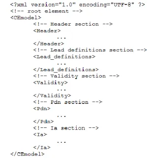
An example CEML file structure is shown in Fig. 1. The header, lead definitions, validity, PDN and IA sections are minimum and mandatory information. The macromodel and IBC elements are optional. Each section, when present, may include specific keywords allowing various parameters to be specified. In order to accommodate a large variety of data types for PDN (IBC) and IA sub-models, keywords specify the format of data (netlist elements or ASCII based measurement file) and whether the data is expressed in the frequency or time domains. Both linear and logarithmic units are acceptable.
It is possible to place, anywhere in the file, notes and links to external documents, in order to better describe the model’s extraction environment and usage. All the information is enclosed within the root keyword <CEmodel> (see Fig. 1).
Fig. 1. Example CEML file structure
III. DEVELOPMENT OF THE EXCHANGE FORMAT
The determination of the features and keywords required to make the exchange format as universal as possible results from requirements and the experience of many industrials and academics, and in particular the co-authors of this paper. A complete list and description of the valid keywords, the description of the different sections may be found in [8]. A. Header Information
It is proposed to define the header information within the Header keyword to organize the different components in a better format and make visual reading of model definitions easier. The minimum details are the model version number, filename and the file version number. Other header contents are freely dimensioned, giving information such as DUT reference, authors’ name, date, measurement method, copyright, disclaimer and documentation.
B. IC Lead or Pin Information
This section described the various leads or pins of the IC under test.
TABLE I. ATTRIBUTES OF LEAD KEYWORD IN THE LEAD_DEFINITIONS SECTION
Lead (Lead_definitions)
Id: pin identity as a valid string (required). Can be the IC pin number Name: Name of the pin as designated in the datasheet (optional). Default = "None"
Mode: Mode in which the pin is used for ICEM-CE ("GND") (optional). Default="None"
Type: Type in which the pin is used for ICEM-CE ("internal", "external") (optional). Default="external"
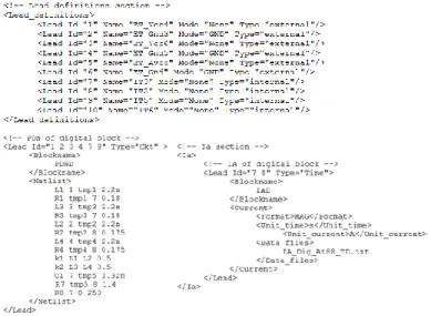
Each lead in the Lead_definitions section is made using the Lead keyword, whose attribute is defined in TABLE I. Several Lead structures are listed one after another to form the Lead_definitions structure. The attributes are chosen in such a way to suit all ICEM-CE requirements. A typical Lead can be specified as:
<Lead Id="1" Name="ETVdd" Type="external"/> Ground leads shall be external terminals seen at the package level. Internal ground terminals can be specified as any other internal terminal (Type=“internal” with Mode=“None”). C. Model Validity Conditions
The Validity keyword is used to represent the conditions in which the ICEM-CE data is defined. This section is strictly informative to the user. The different attributes of the Validity section are listed in TABLE II. There is no particular format for defining the value for this attribute; it shall be easily comprehensible for proper model usage (example: a data string and/or numerical values with units).
TABLE II. DEFINITION OF THE ATTRIBUTES OF THE VALIDITY SECTION
Validity
Power_supply: Power supply range as a string (required)
Temperature_range: Temperature range in which the model is extracted with units (required)
Frequency_range: Frequency range as a string with units (required for frequency-domain model data)
Phase_origin: Origin of phase for frequency-domain IA (required for frequency-domain model data)
Time_range: Time range as a string with units (required for time-domain model data)
Time_origin: Origin of time for domain IA (required for time-domain model data)
D. Macro-models
The Macromodels keyword describes the various Spice macro-models in netlist format. These sub-circuits are references for the PDN or IBC model information.
E. PDN and IBC Information
The Pdn (Ibc) section contains the PDN (IBC) data that describes the model. The PDN or IBC data is defined for one or many IC pins and thus the definition shall be done within a Lead keyword. Those leads defined in the Lead_definitions section are referenced in this part of the file.
TABLE III. ATTRIBUTES OF LEAD KEYWORD IN THE PDN OR IBC SECTION
Lead (Pdn or Ibc)
Id: pin identity as a valid string (required). Can be the IC pin number Blockname: PDN or IBC block name as a valid string (optional) Type: PDN or IBC source parameter ("S", "Z", "Y", "Ckt")
Netlist: PDN or IBC definition using standard netlist format (required if Type="Ckt")
Data_files: PDN or IBC source parameter defined in an external file (required if not List, if Type="S","Y","Z")
List: PDN or IBC parameter list (required if not Data_files, if Type="S","Y","Z")
A few important attributes of the Lead keyword in a Pdn or Ibc section is shown in TABLE III. These attributes are suited for defining the PDN or IBC data as a single or multiple blocks (interconnected or disconnected) that can be represented using single or multi-port S/Y/Z parameters (network parameters) or using Spice-type netlists. In both the cases, data can be defined inline or using external data files. On one hand, the Id attribute with the Pdn keyword can carry both “internal” and “external” terminals. On the other hand,
only “internal” terminals can be used to define the Id attribute with an Ibc section.
When the PDN is represented using a generic Spice-like netlist, then the corresponding information is specified using a Netlist section. An example Pdn section, using a netlist, is shown in Fig. 2.
Fig. 2. Example Pdn section defined using a Spice-like netlist
Alternatively, it is possible to represent the PDN or IBC data using network parameters (S or Z or Y parameters). In such cases, to cater to several data formats, several keywords specify the format of data (magnitude only, magnitude and phase or real and imaginary). When complex data is used, the default unit of phase information is degrees. Data files in ASCII format (example touchstone format or text format) can be used to define the model information.
F. IA Information
The Ia section contains the IA data that describes the model. Similar to the PDN or IBC definition, IA data is defined for specific IC terminals and thus the definition shall be done within a Lead keyword. The different fields of the Lead keyword in the Ia section is shown in TABLE IV. The proposal is suited for defining both time and frequency-domain data.
TABLE IV. ATTRIBUTES OF LEAD KEYWORD IN THE IA SECTION
Lead (Ia section)
Id: pin identity as a valid string (required) – only internal terminals Type: IA source parameter -"time" for time-domain data and "freq" for frequency-domain data (required)
Blockname: IA block name as a valid string (optional) Voltage: IA data as a voltage source (required if not Current) Current: IA data as a current source (required if not Voltage)
The voltage or current data, defining the IA source, can be represented inline using a data list or defined using an external file in ASCII format (example: text format): both real and complex data can be specified. It is also possible to define IA using simpler waveforms such as triangular waveforms using a Pulse keyword, in the time-domain. A typical Ia section using a simulated current source is shown in Fig. 3.
Fig. 3. Example Ia section defined using a simulated current source
IV. ILLUSTRATION USING A MICROCONTROLLER
The ICEM-CE of Atmega88 microcontroller is used to illustrate the CEML description and its efficient exchange. Only the power and the ground systems are taken into account in that model because it is assumed that most the emission comes from the synchronous activity of the chip. The pin-out and the package of that product are shown in Fig. 4.
Fig. 4. Atemega88 pin-out description
The device has two pairs of power pins dedicated for the IOs and the digital parts such as memories and the 8-bit RISC CPU. Another pair supplies all the analog features such as ADC, DAC, Power-on reset, etc.
A. ICEM-CE Description of Atmega88
The ICEM-CE macro-model, depicted in Fig. 5, has four parts. The first and the second part consists of a PDN of the digital part (PDND) and the analog part (PDNA). The third part is the inter block coupling (IBC) which models the substrate “ohmic” loss. The last part is the IA block. The PDN and IBC elements of the model have been extracted from impedance measurements using a network analyzer [3].
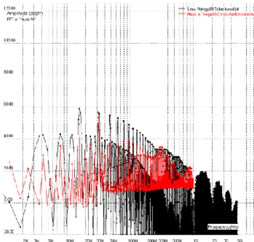
The IA block describes the internal activity of the chip. In this case, the activity is a simple loopless program in which all the internal clock trees are activated (synchronous activity) representing a worst-case scenario. Finally, the resistor R8 models the DC consumption. The IA information is obtained using measurements and is represented in the time-domain as shown in Fig. 6. Its frequency spectrum is also shown.
Fig. 5. ICEM-CE macro-model of Atmega88
Fig. 6. Waveform and spectrum of the measured IA current
B. CEML Description of Atmega88
The ICEM-CE information, discussed previously, is encapsulated in CEML format using the freeware tool CEML editor. A sample screenshot of the exported CEML file describing the lead definitions, PDN (PDND & PDNA) and IA information is shown in Fig. 7. This file is exchanged with other partners (INSA and Valeo) for simulation in their respective tools.
C. Conducted Emission Simulation using IC-EMC
As a first step, the CEML file is exchanged with INSA, Toulouse for simulating the conducted emissions from Atmega88 using IC-EMC, the non-commercial tool dealing with EMC of ICs. The CEML parser was first incorporated within the tool in order to import the exchanged ICEM-CE information of Atmega88. Optionally, the IBIS file was also used to build the 3D structure in IC-EMC as shown in Fig. 8.
Fig. 8. Importing Atmega88 information into IC-EMC
Thanks to CEML file, all information of the ICEM-CE was imported at once without major issues. Since IC-EMC tools currently is not capable of importing a large text file for the IA, an equivalent triangular current source was used to as replacement. The imported structure of PDND in IC-EMC is shown in Fig. 9.
Fig. 9. PDND schematic in IC-EMC after CEML import
Similarly all the other model data were translated into their equivalent Spice models in IC-EMC and ready for time-domain simulations. The input impedance of all Vcc pins connected together with respect to ground terminals (all three grounds are connected together) is compared with measurements in Fig. 10. A good correlation is obtained with the simulated results.
Fig. 10. Comparison of the simulated input impedance of Vcc pins with measurements
The complete schematic for simulating the conducted emissions as per IEC 61967-4 [10] is shown in Fig. 11. For comparison with measurements, it is obvious and important to consider other components used during measurement and board parasitic as well: the IA current is split into two triangular peaks, one at 4 MHz, and one at 16MHz, a 0.5nH on-die serial inductance has been added, and serial parasitic resistances has also been tuned.
Fig. 11. Schematic to simulate the emissions as per IEC 61967-4
Fig. 12. Comparison of simulated IEC 61967-4 reuslts with measurements
The simulated results are compared with the measured values in Fig. 12. TABLE V tabulates the simulated values with the measured values at some specific frequencies corresponding to the clock frequency and its harmonics. Promising results have been obtained; though some differences are expected to exist between measurements and simulation for the following reasons: not all board parasitics could be modeled for IEC 61967-4 simulation, the chip configuration and activity is not the same between IEC 61967-4 measurement and ICEM-CE extraction.
Nevertheless, the objectives of smooth model exchange, its integration into existing simulation tools and its usage have been well achieved.
D. Conducted Emission Simulation using PSpice
As a second step, the CEML file is exchanged with Valeo for simulating the conducted emissions from Atmega88 using PSPICE. Since CEML is not directly importable into PSPICE, there is a need to pass through an intermediate tool, ICEM-CE model builder; the co-developed tool parses the CEML file and exports an equivalent PSpice model, compatible with
3 Vcc pins 3 Gnd pins 3D chip structure ET_Vcc4 ET_Vcc6 ET_AVcc ET_Gnd3 ET_Gnd5 ET_Gnd
PSpice (or any other generic Spice simulator). Using this tool, each of the PDN, IBC and IA blocks are converted into their equivalent generic Spice-like “sub-circuit” and are interconnected as required as shown in Fig. 13.
Fig. 13. Example of parsing CEML information for PSpice
Similar to the simulations with IC-EMC, a good correlation was obtained with measurements of the input impedance and the conducted emissions as per IEC 61967-4 [10]. The simulated results are synthesized in TABLE V. The model exchange proves fruitful once again.
E. Synthesis
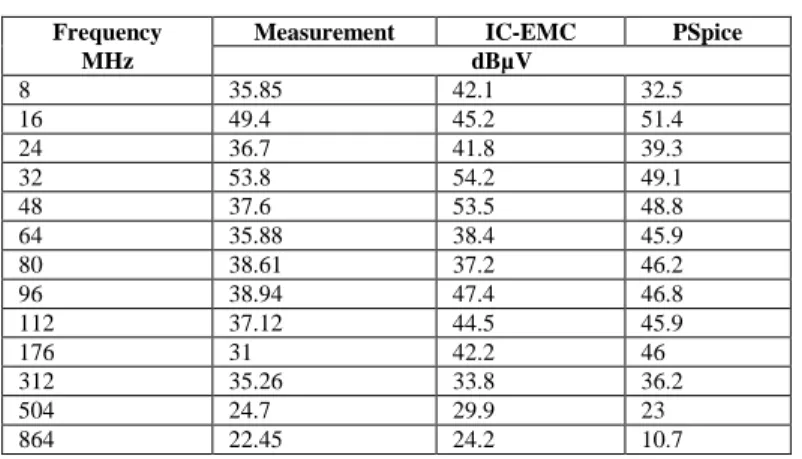
The comparison of the simulated conducted emissions using IC-EMC and PSPICE with measurements at all the harmonic frequencies are synthesized in TABLE V.
TABLE V. SYNTHESIS OF THE SIMULATED RESULTS
Frequency Measurement IC-EMC PSpice
MHz dBµV 8 35.85 42.1 32.5 16 49.4 45.2 51.4 24 36.7 41.8 39.3 32 53.8 54.2 49.1 48 37.6 53.5 48.8 64 35.88 38.4 45.9 80 38.61 37.2 46.2 96 38.94 47.4 46.8 112 37.12 44.5 45.9 176 31 42.2 46 312 35.26 33.8 36.2 504 24.7 29.9 23 864 22.45 24.2 10.7 V. CONCLUSIONS
The development of the ICEM-CE exchange format has involved many potential developers and users. Academic and industrial partners have been consulted and their requirements integrated into the present version.
The current version has been applied and validated on a Atmel microcontroller, Atmega88. The model, encapsulated in CEML format, was exchanged with an academic partner (INSA) and with an industrial partner (Valeo) for implementation in different SPICE-like tools: IC-EMC was used by INSA and PSPICE was used by Valeo. A freeware tool, CEML editor, co-developed by the authors, was used to export and import CEML data. The exchange was smooth and efficient that no issues were faced during information exchange between different partners. The model data was used
to predict the conducted emissions as per IEC 61967-4 standard with encouraging results. The simulated results correlated well with the measured data and thus the model was validated. Additionally, since all information of the ICEM-CE is well-defined within the CEML file, its productive usage is guaranteed.
New features will undoubtedly be required in the future. Some features have been left open, as their use is not clearly defined as of date. An attempt has been made to project these requirements into the future. This is a major advantage of the use of XML. The exchange format has been developed around the ICEM-CE and is currently being envisaged for other modeling methods within the IEC 62433 framework, in particular, ICEM – Radiated Emission (future IEC 62433 – 3) [11] and IC Immunity Model – Conducted Immunity (future IEC 62433-4) [12].
For the exchange format to become accepted by the community, it is important that industrials and academics involved in IC modeling use it now. We are currently working to fully incorporate the CEML format within IC-EMC. The standardization process gives the exchange format an official and international backing, but its true acceptance and future evolution can only come from the users.
References
[1] S. Ben Dhia, M. Ramdani, E. Sicard and J.L. Levant, Electromagnetic compatibility of integrated circuits, Springers (2006)
[2] J. L. Levant, C. Marot, M. Meyer, and M. Ramdani, “Solving ASIC decoupling with the ICEM-CE model,” presented at the 7th Int. Workshop Electromagn. Compat. Integr. Circuits (EMC COMPO), Toulouse, France, 2009.
[3] International Electrotechnical Commission, “IEC 62433-2 Edition 1.0: Models of integrated circuits for EMI behavioural simulation – Conducted emissions modelling (ICEM-CE)”, IEC standard 2008, www.iec.ch.
[4] C. Labussiere-Dorgan; S. Bendhia, E. Sicard, T. Junwu, H. J. Quaresma, C. Lochot, B. Vrignon, “Modeling the Electromagnetic Emission of a Microcontroller Using a Single Model,” IEEE Transactions on Electromagnetic Compatibility, vol.50, no.1, pp.22-34, Feb. 2008. [5] JL Levant; M. Ramdani; R. Perdriau; M. Drissi, “EMC Assessment at
Chip and PCB Level: Use of the ICEM Model for Jitter Analysis in an Integrated PLL,” IEEE Transactions on Electromagnetic Compatibility, vol.49, no.1, pp.182-191, Feb. 2007.
[6] C. Marot, “Simulation of emission and immunity of systems and modules electronics (SEISME)”, Cooperative and Federative French National project of Embedded electronic actors, EMC COMPO 2013, Nara, Japan, Dec. 2013.
[7] Extensible Markup Language (XML) 1.0 (Fourth Edition), W3C Recommendation 16 August 2006, edited in place 29 September 2006. [8] International Electrotechnical Commission, “IEC/future IS 62433-2
Edition 2.0: Models of integrated circuits for EMI behavioural simulation – Conducted emissions modelling (ICEM-CE)”, www.iec.ch. [9] IC-EMC, http://www.ic-emc.org/
[10] International Electrotechnical Commission, “IEC TR 61967-4-1: Integrated circuits – Measurement of electromagnetic emissions, 150 kHz to 1 GHz”, www.iec.ch.
[11] International Electrotechnical Commission, “IEC/future IS 62433-3: Models of Integrated circuits for EMI behavioural simulation – Radiated emissions modelling (ICEM-RE)”, www.iec.ch.
[12] International Electrotechnical Commission, “IEC/future IS 62433-4: Models of Integrated circuits for RF Immunity behavioural simulation – Conducted immunity modelling (ICIM-CI)”, www.iec.ch.