HAL Id: hal-01737927
https://hal.sorbonne-universite.fr/hal-01737927
Submitted on 20 Mar 2018
HAL is a multi-disciplinary open access archive for the deposit and dissemination of sci-entific research documents, whether they are pub-lished or not. The documents may come from teaching and research institutions in France or abroad, or from public or private research centers.
L’archive ouverte pluridisciplinaire HAL, est destinée au dépôt et à la diffusion de documents scientifiques de niveau recherche, publiés ou non, émanant des établissements d’enseignement et de recherche français ou étrangers, des laboratoires publics ou privés.
Distributed under a Creative Commons Attribution| 4.0 International License
Viacheslav Mazlin, Peng Xiao, Eugénie Dalimier, Kate Grieve, Kristina Irsch,
José-Alain Sahel, Mathias Fink, A. Claude Boccara
To cite this version:
Viacheslav Mazlin, Peng Xiao, Eugénie Dalimier, Kate Grieve, Kristina Irsch, et al.. In vivo high resolution human corneal imaging using full-field optical coherence tomography. Biomedical optics ex-press, Optical Society of America - OSA Publishing, 2018, 9 (2), pp.557-568. �10.1364/BOE.9.000557�. �hal-01737927�
In vivo
high resolution human corneal imaging
using full-field optical coherence tomography
V
IACHESLAVM
AZLIN,
1P
ENGX
IAO,
1E
UGÉNIED
ALIMIER,
2K
ATEG
RIEVE,
3,4K
RISTINAI
RSCH,
3,4,5J
OSÉ-A
LAINS
AHEL,
3,4,6M
ATHIASF
INK,
1ANDA.
C
LAUDEB
OCCARA1,2,*1Institute Langevin, ESPCI PARIS, PSL Research University, 1 Rue Jussieu, Paris, 75005, France 2LLTech SAS, 29 Rue du Faubourg Saint Jacques, Paris, 75014, France
3Vision Institute/CIC 1423, UPMC-Sorbonne Universities, UMR_S 968/INSERM, U968/CNRS,
UMR_7210, 17 Rue Moreau, Paris, 75012, France
4Quinze-Vingts National Eye Hospital, 28 Rue de Charenton, Paris, 75012, France
5Laboratory of Ophthalmic Instrument Development, The Wilmer Eye Institute, The Johns Hopkins
University School of Medicine, 600 N Wolfe Street, Baltimore, MD 21287, USA
6Department of Ophthalmology, University of Pittsburgh School of Medicine, 3550 Terrace Street,
Pittsburgh, PA 15213, USA
Abstract: We present the first full-field optical coherence tomography (FFOCT) device
capable of in vivo imaging of the human cornea. We obtained images of the epithelial structures, Bowman’s layer, sub-basal nerve plexus (SNP), anterior and posterior stromal keratocytes, stromal nerves, Descemet’s membrane and endothelial cells with visible nuclei. Images were acquired with a high lateral resolution of 1.7 µm and relatively large field-of-view of 1.26 mm x 1.26 mm – a combination, which, to the best of our knowledge, has not been possible with other in vivo human eye imaging methods. The latter together with a contactless operation, make FFOCT a promising candidate for becoming a new tool in ophthalmic diagnostics.
© 2018 Optical Society of America under the terms of the OSA Open Access Publishing Agreement
OCIS codes: (110.4500) Optical coherence tomography; (170.4460) Ophthalmic optics and devices; (170.0110) Imaging systems; (170.3880) Medical and biological imaging; (170.0170) Medical optics and biotechnology; (170.3890) Medical optics instrumentation.
References and links
1. D. Pascolini and S. P. Mariotti, “Global estimates of visual impairment: 2010,” Br. J. Ophthalmol. 96(5), 614– 618 (2012).
2. J. P. Whitcher, M. Srinivasan, and M. P. Upadhyay, “Corneal blindness: a global perspective,” Bull. World Health Organ. 79(3), 214–221 (2001).
3. WHO white paper, “Universal eye health: a global action plan 2014–2019,” (WHO, 2013), http://www.who.int/blindness/actionplan/en/.
4. P. Garg, P. V. Krishna, A. K. Stratis, and U. Gopinathan, “The value of corneal transplantation in reducing blindness,” Eye (Lond.) 19(10), 1106–1114 (2005).
5. E. Villani, C. Baudouin, N. Efron, P. Hamrah, T. Kojima, S. V. Patel, S. C. Pflugfelder, A. Zhivov, and M. Dogru, “In vivo confocal microscopy of the ocular surface: from bench to bedside,” Curr. Eye Res. 39(3), 213– 231 (2014).
6. R. L. Niederer and C. N. McGhee, “Clinical in vivo confocal microscopy of the human cornea in health and disease,” Prog. Retin. Eye Res. 29(1), 30–58 (2010).
7. D. Huang, E. A. Swanson, C. P. Lin, J. S. Schuman, W. G. Stinson, W. Chang, M. R. Hee, T. Flotte, K. Gregory, C. A. Puliafito, and J. G. Fujimoto, “Optical coherence tomography,” Science 254(5035), 1178–1181 (1991). 8. A. F. Fercher, “Optical coherence tomography,” J. Biomed. Opt. 1(2), 157–173 (1996).
9. E. A. Swanson, J. A. Izatt, M. R. Hee, D. Huang, C. P. Lin, J. S. Schuman, C. A. Puliafito, and J. G. Fujimoto, “In vivo retinal imaging by optical coherence tomography,” Opt. Lett. 18(21), 1864–1866 (1993).
10. M. R. Hee, J. A. Izatt, E. A. Swanson, D. Huang, J. S. Schuman, C. P. Lin, C. A. Puliafito, and J. G. Fujimoto, “Optical Coherence Tomography of the Human Retina,” Arch. Ophthalmol. 113(3), 325–332 (1995). 11. J. A. Izatt, M. R. Hee, E. A. Swanson, C. P. Lin, D. Huang, J. S. Schuman, C. A. Puliafito, and J. G. Fujimoto,
“Micrometer-Scale Resolution Imaging of the Anterior Eye In Vivo With Optical Coherence Tomography,” Arch. Ophthalmol. 112(12), 1584–1589 (1994).
#312708
12. S. Radhakrishnan, A. M. Rollins, J. E. Roth, S. Yazdanfar, V. Westphal, D. S. Bardenstein, and J. A. Izatt, “Real-Time Optical Coherence Tomography of the Anterior Segment at 1310 nm,” Arch. Ophthalmol. 119(8), 1179–1185 (2001).
13. J. Schuman, Optical Coherence Tomography Of Ocular Diseases (SLACK Incorporated, 2013).
14. R. Steinert and D. Huang, Anterior Segment Optical Coherence Tomography (SLACK Incorporated, 2015). 15. V. Christopoulos, L. Kagemann, G. Wollstein, H. Ishikawa, M. L. Gabriele, M. Wojtkowski, V. Srinivasan, J. G.
Fujimoto, J. S. Duker, D. K. Dhaliwal, and J. S. Schuman, “In Vivo Corneal High-Speed, Ultra High-Resolution Optical Coherence Tomography,” Arch. Ophthalmol. 125(8), 1027–1035 (2007).
16. B. J. Kaluzny, J. J. Kałuzny, A. Szkulmowska, I. Gorczyńska, M. Szkulmowski, T. Bajraszewski, M. Wojtkowski, and P. Targowski, “Spectral Optical Coherence Tomography: A Novel Technique for Cornea Imaging,” Cornea 25(8), 960–965 (2006).
17. F. Beer, A. Wartak, R. Haindl, M. Gröschl, B. Baumann, M. Pircher, and C. K. Hitzenberger, “Conical scan pattern for enhanced visualization of the human cornea using polarization-sensitive OCT,” Biomed. Opt. Express 8(6), 2906–2923 (2017).
18. R. Yadav, K. S. Lee, J. P. Rolland, J. M. Zavislan, J. V. Aquavella, and G. Yoon, “Micrometer axial resolution OCT for corneal imaging,” Biomed. Opt. Express 2(11), 3037–3046 (2011).
19. R. M. Werkmeister, S. Sapeta, D. Schmidl, G. Garhöfer, G. Schmidinger, V. Aranha Dos Santos, G. C. Aschinger, I. Baumgartner, N. Pircher, F. Schwarzhans, A. Pantalon, H. Dua, and L. Schmetterer, “Ultrahigh-resolution OCT imaging of the human cornea,” Biomed. Opt. Express 8(2), 1221–1239 (2017).
20. K. Bizheva, B. Tan, B. MacLelan, O. Kralj, M. Hajialamdari, D. Hileeto, and L. Sorbara, “Sub-micrometer axial resolution OCT for in-vivo imaging of the cellular structure of healthy and keratoconic human corneas,” Biomed. Opt. Express 8(2), 800–812 (2017).
21. A. Podoleanu, J. Rogers, G. Dobre, R. Cucu, and D. Jackson, “En-face OCT imaging of the anterior chamber,” Proc. SPIE 4619, 9 (2002).
22. R. Tahiri Joutei Hassani, H. Liang, M. El Sanharawi, E. Brasnu, S. Kallel, A. Labbé, and C. Baudouin, “En-face Optical Coherence Tomography as a Novel Tool for Exploring the Ocular Surface: A Pilot Comparative Study to Conventional B-Scans and in Vivo Confocal Microscopy,” Ocul. Surf. 12(4), 285–306 (2014).
23. Y. Yasuno, V. D. Madjarova, S. Makita, M. Akiba, A. Morosawa, C. Chong, T. Sakai, K. P. Chan, M. Itoh, and T. Yatagai, “Three-dimensional and high-speed swept-source optical coherence tomography for in vivo investigation of human anterior eye segments,” Opt. Express 13(26), 10652–10664 (2005).
24. M. Gora, K. Karnowski, M. Szkulmowski, B. J. Kaluzny, R. Huber, A. Kowalczyk, and M. Wojtkowski, “Ultra high-speed swept source OCT imaging of the anterior segment of human eye at 200 kHz with adjustable imaging range,” Opt. Express 17(17), 14880–14894 (2009).
25. I. Grulkowski, J. J. Liu, B. Potsaid, V. Jayaraman, C. D. Lu, J. Jiang, A. E. Cable, J. S. Duker, and J. G. Fujimoto, “Retinal, anterior segment and full eye imaging using ultrahigh speed swept source OCT with vertical-cavity surface emitting lasers,” Biomed. Opt. Express 3(11), 2733–2751 (2012).
26. D. Hillmann, G. Franke, L. Hinkel, T. Bonin, P. Koch, and G. Hüttmann, “Off-axis full-field swept-source optical coherence tomography using holographic refocusing,” Proc. SPIE 8571, 857104 (2013).
27. P. Tankam, Z. He, Y. J. Chu, J. Won, C. Canavesi, T. Lepine, H. B. Hindman, D. J. Topham, P. Gain, G. Thuret, and J. P. Rolland, “Assessing microstructures of the cornea with Gabor-domain optical coherence microscopy: pathway for corneal physiology and diseases,” Opt. Lett. 40(6), 1113–1116 (2015).
28. S. Chen, X. Liu, N. Wang, X. Wang, Q. Xiong, E. Bo, X. Yu, S. Chen, and L. Liu, “Visualizing Micro-anatomical Structures of the Posterior Cornea with Micro-optical Coherence Tomography,” Sci. Rep. 7(1), 10752 (2017).
29. F. Aptel, N. Olivier, A. Deniset-Besseau, J. M. Legeais, K. Plamann, M. C. Schanne-Klein, and E. Beaurepaire, “Multimodal Nonlinear Imaging of the Human Cornea,” Invest. Ophthalmol. Vis. Sci. 51(5), 2459–2465 (2010). 30. G. Latour, I. Gusachenko, L. Kowalczuk, I. Lamarre, and M. C. Schanne-Klein, “In vivo structural imaging of
the cornea by polarization-resolved second harmonic microscopy,” Biomed. Opt. Express 3(1), 1–15 (2012). 31. J. Stave, G. Zinser, G. Grümmer, and R. Guthoff, “Der modifizierte Heidelberg-Retina-Tomograph HRT. Erste
Ergebnisse einer In-vivo-Darstellung von kornealen Strukturen,” Ophthalmologe 99(4), 276–280 (2002). 32. R. F. Guthoff, A. Zhivov, and O. Stachs, “In vivo confocal microscopy, an inner vision of the cornea - a major
review,” Clin. Experiment. Ophthalmol. 37(1), 100–117 (2009).
33. E. Villani, C. Baudouin, N. Efron, P. Hamrah, T. Kojima, S. V. Patel, S. C. Pflugfelder, A. Zhivov, and M. Dogru, “In Vivo Confocal Microscopy of the Ocular Surface: From Bench to Bedside,” Curr. Eye Res. 39(3), 213–231 (2014).
34. A. Zhivov, O. Stachs, J. Stave, and R. F. Guthoff, “In vivo three-dimensional confocal laser scanning microscopy of corneal surface and epithelium,” Br. J. Ophthalmol. 93(5), 667–672 (2009).
35. J. Stave and R. Guthoff, “First results of in-vivo visualization of the tear film and structures of the cornea with a modified confocal laser scanning ophthalmoscope,” Ophthalmologe 95(2), 104–109 (1998).
36. R. Guthoff, Atlas of Confocal Laser Scanning in-vivo Microscopy in Ophthalmology (Springer-Verlag Berlin Heidelberg, 2016).
37. E. Beaurepaire, A. C. Boccara, M. Lebec, L. Blanchot, and H. Saint-Jalmes, “Full-field optical coherence microscopy,” Opt. Lett. 23(4), 244–246 (1998).
38. A. Dubois, Handbook of Full-Field Optical Coherence Microscopy: Technology and Applications (Pan Stanford publishing, 2016).
39. P. Xiao, M. Fink, and A. C. Boccara, “Full-field spatially incoherent illumination interferometry: a spatial resolution almost insensitive to aberrations,” Opt. Lett. 41(17), 3920–3923 (2016).
40. P. Xiao, M. Fink, and A. C. Boccara, “Adaptive optics full-field optical coherence tomography,” J. Biomed. Opt. 21(12), 121505 (2016).
41. LLTech Imaging, http://www.lltechimaging.com.
42. E. Auksorius and A. C. Boccara, “Fingerprint imaging from the inside of a finger with full-field optical coherence tomography,” Biomed. Opt. Express 6(11), 4465–4471 (2015).
43. K. Grieve, M. Paques, A. Dubois, J. Sahel, C. Boccara, and J. F. Le Gargasson, “Ocular Tissue Imaging Using Ultrahigh-Resolution, Full-Field Optical Coherence Tomography,” Invest. Ophthalmol. Vis. Sci. 45(11), 4126– 4131 (2004).
44. M. Akiba, N. Maeda, K. Yumikake, T. Soma, K. Nishida, Y. Tano, and K. P. Chan, “Ultrahigh-resolution imaging of human donor cornea using full-field optical coherence tomography,” J. Biomed. Opt. 12(4), 041202 (2007).
45. W. Ghouali, K. Grieve, S. Bellefqih, O. Sandali, F. Harms, L. Laroche, M. Paques, and V. Borderie, “Full-Field Optical Coherence Tomography of Human Donor and Pathological Corneas,” Curr. Eye Res. 40(5), 526–534 (2015).
46. M. Borderie, K. Grieve, K. Irsch, D. Ghoubay, C. Georgeon, C. De Sousa, L. Laroche, and V. M. Borderie, “New parameters in assessment of human donor corneal stroma,” Acta Ophthalmol. 95(4), e297–e306 (2017). 47. K. Grieve, A. Dubois, M. Simonutti, M. Paques, J. Sahel, J. F. Le Gargasson, and C. Boccara, “In vivo anterior
segment imaging in the rat eye with high speed white light full-field optical coherence tomography,” Opt. Express 13(16), 6286–6295 (2005).
48. A. Dubois, G. Moneron, and C. Boccara, “Thermal-light full-field optical coherence tomography in the 1.2μm wavelength region,” Opt. Commun. 266(2), 738–743 (2006).
49. E. Bennett and B. Weissman, Clinical Contact Lens Practice (Lippincott Williams & Wilkins, 2005). 50. S. Labiau, G. David, S. Gigan, and A. C. Boccara, “Defocus test and defocus correction in full-field optical
coherence tomography,” Opt. Lett. 34(10), 1576–1578 (2009).
51. J. Schindelin, C. T. Rueden, M. C. Hiner, and K. W. Eliceiri, “The ImageJ ecosystem: An open platform for biomedical image analysis,” Mol. Reprod. Dev. 82(7-8), 518–529 (2015).
52. Q. Tseng, E. Duchemin-Pelletier, A. Deshiere, M. Balland, H. Guillou, O. Filhol, and M. Théry, “Spatial organization of the extracellular matrix regulates cell-cell junction positioning,” Proc. Natl. Acad. Sci. U.S.A. 109(5), 1506–1511 (2012).
53. P. Xiao, M. Fink, and A. C. Boccara, “Combining FF-OCT with SD-OCT for retinal imaging,” in Optical Coherence Imaging Techniques and Imaging in Scattering Media II, M. Wojtkowski, ed., Vol. 10416 of SPIE Proceedings (Optical Society of America, 2017), paper 104160K.
1. Introduction
Corneal diseases are the third major cause of blindness worldwide [1], making 1.5 to 2.0 million people unilaterally blind every year [2]. Considering that more than 90% of the affected population lives in developing countries [3], cost-effective disease prevention through early diagnosis is preferable over costly surgical interventions [4]. However, accurate diagnosis at the initial stage, when disease can still be cured without negative consequences for vision, is complicated. Many corneal diseases have similar symptoms on a macroscopic level and can be distinguished only with a micrometer resolution instrument, capable of resolving microbiological markers, specific to the disease (e.g., cysts or fungi), as well as capable of distinguishing cell-level changes in the structural characteristics of the cornea itself (e.g., cell shapes, cell and nerve densities) [5,6]. However, slit lamp biomicroscopy, the gold standard routinely used in ophthalmology practice, is qualitative and offers poor resolution.
Ex vivo microscopy of ocular surface scrapings gives high resolution, but is not a routine
procedure due to its invasiveness, high false-negative rate and time delay needed for growing corneal cultures [5]. Optical coherence tomography (OCT) [7,8] is an interferometric technique, which has revolutionized ophthalmology within two decades and whose use today is widespread in clinics. OCT applications to in vivo imaging of the anterior and posterior parts of the human eye are extensively covered in the literature [9–14]. An ever improving array of OCT devices have been applied to in vivo human cornea visualization [15,16], with the most recent instruments benefiting from the improved signal quality [17], micron [18,19] and even sub-micron cellular level [20] axial resolutions. However, they provide cross-sectional images and lack the possibility of en face high resolution viewing. More precisely, several other OCT configurations are able to acquire en face corneal images, but have drawbacks of their own. For example, conventional en face OCT [21,22], rapidly evolving
swept-source OCT (SS-OCT) [23–25] and full-field SS-OCT [26] can visualize the human cornea in vivo, but have relatively low lateral resolution. Gabor domain optical coherence microscopy (OCM) [27] and µOCT [28] were able to acquire high resolution en face images with visible stromal keratocytes and endothelial cells, however until now only from ex vivo posterior cornea. Nonlinear microscopy demonstrated high-contrast high-resolution en face images of the entire human cornea ex vivo [29] and, recently, images of the collagen fibrils in rat cornea in vivo [30], but requirements for a long acquisition time make its application limited to immobilized animal studies. In the past decade, in vivo confocal microscopy (CM) of the cornea [31] has made its way from the bench to bedside [32]. This technology has improved understanding of in vivo human corneal structures, as well as pathophysiologic mechanisms associated with various corneal diseases, and has helped in the assessment of prognosis and treatment [33]. In vivo CM provides en face images with a lateral resolution of 1-2 μm and an axial resolution of 7.6 μm [34]. According to the principle of CM [31], only one pixel is imaged at a time and a complete en face image is formed by rapid point-by-point scanning. Eye movements and scanning speed limitations set the maximum achievable field-of-view, which currently is about 400 μm x 400 μm. Sectioning thickness is inversely proportional to the square of the numerical aperture (NA), meaning that a high axial resolution of 7.6 μm requires very high NA, typically found in contact water-immersion microscope objectives. Disadvantages associated with contact investigation, aside from discomfort to the patient, are the requirement for prior instillation of topical anesthetics and viscous gels, known to produce alterations to the corneal surface, risk of corneal infection through contact and applanation artifacts, such as tissue folds and compression of the cornea, which pose a risk of corneal abrasion [34]. A non-contact modification of CM [35,36], equipped with long focal length air objectives, allowed visualization of pre-corneal tear film, corneal stroma and endothelium. However, decreased axial resolution, resulting from lowering microscope objective NA, and strong surface reflection prohibited imaging of the fine layered nerve plexus and epithelial structures.
Full-field optical coherence tomography (FFOCT) is a variation of OCT, in which 2D en
face tangential optical slices are directly recorded on a camera without point-by-point lateral
scanning [37,38]. The FFOCT microscope combines the penetration capability and high axial resolution sectioning of OCT with the high transverse resolution of confocal microscopy. Additionally, in FFOCT, contrary to confocal microscopy, axial resolution (dependent on the bandwidth of the light source) and lateral resolution (dependent on the resolving power of the objectives) are completely decoupled. This implies that FFOCT with moderate numerical aperture objectives can achieve a larger field-of-view, along with a long working distance enabling non-contact operation, and at the same time high lateral and axial resolutions down to 1 µm. Recently, another particular feature of FFOCT was discovered, that is, geometrical aberrations do not decrease spatial resolution [39], but only lower the signal-to-noise ratio (SNR), which can be recovered with adaptive optics [40]. FFOCT has been demonstrated in a variety of applications and is now commercially available [41]. It has been applied to imaging of biopsies of various tissues, studies in developmental biology, in vivo endoscopy, material characterization [38] and, recently, for in vivo human internal fingerprint imaging [42], useful for personal identification purposes. Regarding ophthalmic applications, FFOCT has been used for the characterization of various ex vivo tissues from the anterior and posterior segments of animal eyes [43]. It was shown to provide valuable assessment of human corneal grafts, which could potentially improve outcome of corneal transplantation [44–46]. Grieve and colleagues pioneered in vivo ocular FFOCT by imaging cellular features of the anterior segment of the rat eye [47]. However, until now, in vivo FFOCT imaging of the human cornea has not been achieved.
In this paper, we demonstrate the first FFOCT device capable of in vivo human cornea imaging. The instrument has a high lateral resolution of 1.7 µm and axial resolution of 7.7 µm, while at the same time providing a relatively large field-of-view of 1.26 mm x 1.26 mm.
An acquisition time of 3.4 ms was sufficiently short to successfully acquire single en face frames with FFOCT in the presence of eye movements. Use of an NIR light source and non-contact (air) objectives made the imaging procedure comfortable for the subject. We obtained images of the epithelial structures, Bowman’s layer, sub-basal nerve plexus (SNP), anterior and posterior stromal keratocytes, stromal nerves, Descemet’s membrane and endothelial cells with visible nuclei. FFOCT images are compared to CM images obtained on the same subject.
2. Methods
2.1 Non-contact high resolution FFOCT
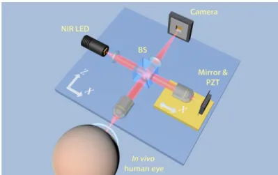
A schematic drawing of the FFOCT instrument is presented in Fig. 1. The instrument is based on a microscope in a Linnik interferometric configuration, typically used in FFOCT imaging. Illumination is provided by a 850 nm light-emitting diode (LED) source (model M850LP1, Thorlabs, USA). A 1 mm x 1 mm chip can emit up to 1600 mW of power spread in a broad angle of 150 degrees. The source has a 30 nm bandwidth, resulting in a theoretical axial resolution of 7.7 µm in the cornea. Light from the LED is collected by the aspheric lens and directed to the cubic beam splitter (BS), which divides the illumination with equal splitting ratio of 50:50 into the sample and reference arms. In both arms, light passes through the identical 10 X/0.3 NA air microscope objectives (Olympus, Japan), which provide a theoretical transverse resolution of 1.7 µm (Rayleigh criterion). Resolution of 1.7 µm was experimentally confirmed by measuring the visible diameters (FWHM) of 80 nm gold nanoparticles. The objectives focus the light on the cornea in the sample arm and on a partially reflecting mirror in the reference arm. The mirror is an absorbing neutral density (ND) filter with 4% reflectivity. A low reflectivity value is selected to obtain high detection sensitivity, which, according to the established theories of FFOCT [38,48], is maximized, when the reflectivity of the reference mirror matches that of the sample. Reflectivity of the cornea, estimated from the Fresnel equations, is around 2% [49]. By using a reference mirror with a close reflectivity of 4%, we can expect only about 1% lower sensitivity comparing to the ideal condition (with 2% reflectivity mirror). Use of an ND filter instead of a glass plate enables elimination of ghost reflections from the back surface of the filter.
Fig. 1. Schematic illustration of the FFOCT set-up. Illumination: NIR LED; BS: beam splitter; PZT: piezoelectric stage actuator. A precision motorized translation stage (yellow) can change the reference arm length by moving altogether the reference arm components (air objective, mirror and PZT) nearer and farther from the BS along the X axis. Two orthogonal motorized translation stages (blue) underneath the entire set-up can move the interferometer along the X and Z axes. Translation along the Z axis nearer and farther from the eye allows to focus at different layers of the cornea, while translation along the X axis helps to find an optimal imaging position near the corneal apex.
Light in the sample arm, backscattered from the different planes in the cornea, and light in the reference arm backscattered from a single mirror plane are collected by the objectives, recombined on the BS and directed at the sensor. Images are captured by a high full-well-capacity CMOS camera (model Q-2A750-CXP, Adimec, Netherlands). If the path length difference between the sample beam coming from the corneal plane of focus and reference beam coming from the mirror is within the temporal coherence length of the light source, then the combined beams form an interference image on the camera. Additionally, non-interfering light, arising from other planes of the cornea, which are still within the objective’s depth of focus, also reaches the camera. In order to select only the interference signal, coming from the slice of interest, and suppress unwanted non-interfering parts, we use a two-phase shifting scheme. More precisely, a piezoelectric translation stage (PZT) shifts the reference mirror with a step function at 275 Hz, in synchronization with image acquisition by the CMOS camera at 550 Hz. Therefore, two consecutive images are captured per modulation period of the reference mirror. By means of signal processing, the module of the difference between two images is taken, containing only the signal originating from the coherence volume, which is the slice of interest. A single image on the camera is recorded in 1.7 ms, resulting in 3.4 ms per complete en face image.
A custom modification of the commercial software (LLTech SAS, France) enables synchronization of the camera, the piezoelectric translation stage and the LED. Images are displayed in real-time thanks to rapid image processing.
2.2 In vivo image acquisition and processing
We utilize NIR illumination at 850 nm, which is one of the most commonly used wavelengths for clinical ophthalmic imaging. This wavelength is comfortably viewed by patients, due to the low sensitivity of the retina to NIR light, and poses no danger associated with photochemical damage. In order to improve patient comfort during the experiment, the LED is operated in a uniformly pulsed mode with alternating 34 ms duration pulses (10 en face images are acquired during a single pulse) and 1000 ms duration pauses. These pulses are well below maximum permissible exposures (MPEs) specified by ophthalmic safety standards (ANSI Z80.36-2016 and ISO 15004-2: 2007). As shown in Eq. (1), even when considering the worst-case scenario of continuous illumination (no pauses), weighted retinal irradiance is 14 times smaller than the MPE for Group 1 instruments (for which no potential hazard exists), as specified by both ANSI and ISO standards:
1400 2 2 retinal exposure 380 ( ) 49 mW 700mW . E E R MPE cm cm
(1)Such a small retinal irradiance is expected, as focusing the light beam on the cornea results in a widely spread beam on the retina. Considering the same worst-case scenario of continuous illumination for the cornea, we see that corneal exposure is 1.5 times below the MPE for Group 1 instruments, as specified by ANSI:
1200 2 2 corneal exposure 380 2.6W 4W . E E MPE cm cm
(2)The ISO standard for corneal safety, however, is much stricter than ANSI, when using NIR illumination. For an 850 nm wavelength, as in our case, ISO adds 20 mW/cm2 and 100
mW/cm2 limits for Group 1 and Group 2 instruments, respectively, to the 4 W/cm2 limit of
ANSI. Optical safety calculation according to ISO in Eq. (3) shows that in case of pulsed illumination, average corneal exposure by our device is 1.2 times smaller than the MPE for Group 2 instruments:
2500 2 2 average corneal 770 exposure 86mW 100mW . E E MPE cm cm
(3)Therefore, optical safety is assured with our device according to both ANSI and ISO standards. ISO requires use of a pulsed illumination, while ANSI permits continuous exposure. We utilized pulsed illumination to conform to both standards.
The study was carried out on a 27-year-old male subject with a healthy cornea, which was confirmed by an eye examination preceding the experiment. Informed consent was obtained from the subject and the experimental procedures adhered to the tenets of the Declaration of Helsinki. During the experiment, the subject rested his chin and temples on a custom-built headrest, while looking at a fixation target within the device.
In FFOCT it is crucial that the sample and reference arms are as symmetric as possible in terms of optical path length. However, as we attempt to focus deeper inside the corneal tissue, in the sample arm, the optical path in air is progressively replaced by the optical path in cornea with a higher refractive index. As a result of this refractive index change, the coherence plane is shifted backward towards the objective, while the focus is shifted forward. This shift of the coherence plane out of focus degrades image quality and the signal quickly vanishes. Our laboratory has developed a method to compensate for this effect and to restore the signal by extending the reference arm [50]. More precisely, using Eq. (4) one can calculate the distance ( ) z , by which the reference arm should be extended in order to match the coherence plane with a new focus position to allow imaging at a given depth z in the cornea. 2 1.376 1 ( ) . 1.376 z z (4)
Here, the values of 1.376 and 1 represent the refractive indexes of the cornea and air, respectively. For example, to image the endothelial cell layer, located 540 µm inside a subject’s cornea, the reference arm is extended by approximately 350 µm, and the entire device is moved to have the endothelial layer in the focus. The mentioned approach is easy to implement for imaging static samples, however imaging living eyes, which are constantly moving in a rapid way, due to involuntary movements, requires the real-time, precise and fast reference arm adjustment, which is very challenging. To facilitate the acquisition of images, the following paradigm was applied. Before starting image acquisition, we select the corneal layer of interest and extend the reference arm to compensate for the separation between the coherence plane and the focus associated with this layer. Then we start image acquisition (piezo modulation and camera) and view in real time the captured en face images. Initially, as the layer of interest is out of the focus, only noise is visible in the images. However, by moving the entire microscope with a motorized translation stage along the Z axis, and keeping the cornea approximately in the objective focus, there is a chance that at some moment microscope will focus on the selected corneal layer. When it happens, coherence plane matches with focus plane and optical path of the sample arm matches with optical path of the reference arm, as a result a tomography image of the layer appears on display and is manually saved. Device allows to save several consecutive en face images in a row without a pause between the frames.
To decrease the contribution of light originating from the strong air-tear film reflection, the device was aligned to have the optical axis shifted, in a parallel fashion, relative to the central corneal axis. This shift was achieved by a user controlling the position of the entire set-up along the X-axis using the motorized translation stage.
In order to increase SNR, several images from the same coherence layer were recorded, registered with ImageJ [51, 52] to remove misalignment, resulting from lateral eye
movements, and averaged. This process performed on 10 images allowed to increase the SNR to 74 dB, compared to 60 dB SNR for a single image. Experimentally, SNR was estimated as the ratio of the average squared signal A2 and the noise variance in the image 2
2 2
1010·
SNR dB log A . Whereas the camera in FFOCT measures intensity, FFOCT processing (image subtraction and module) results in images of amplitude. When calculating SNR for amplitude measures, they must be squared, which leads to SNR being proportional to the number of accumulations N. Therefore, averaging of N 10 images is expected to yield an SNR increase in dB of 10·log10
N 10dB , a value close to the experimentallydetermined increase of 14 dB. The images shown below typically represent the result after 10 frames averaging.
Interference fringe artifacts, sometimes present in the FFOCT images, can be filtered in the Fourier domain. Typically, fringes have a circular shape, which is the result of mixing a plane wave from the reference arm with the spherical waves from the curved cornea. As a result, in the Fourier domain, fringes are visible as a ring. Such rings can be closed or unclosed, depending if the corneal apex falls within or out of the image. Filtering is done by masking the ring (or ring parts), associated with the fringes.
2.3 Comparison with confocal microscopy
For comparison purposes, corneal images from the same subject were also obtained with a contact CM (HRT II with Rostock cornea module; Heidelberg Engineering, GmbH), equipped with a 0.9 NA microscope objective. Device provided 300 µm x 300 µm field-of-view images with 1 – 2 µm lateral and 7.6 µm axial resolutions [34]. Prior to examination, one drop of a topical anesthetic, oxybuprocaine and one drop of a gel tear substitute, carbomer 0.3% (Gel-larmes, carbomer-974 P; Théa, Switzerland), with a refraction index similar to that of the cornea, were instilled in the eye.
3. Results
Figure 2 shows in vivo images of the anterior part of the human cornea, obtained with FFOCT and CM.
Fig. 2. In vivo anterior human cornea images, obtained with FFOCT and CM. Due to the curvature of the human eye and relatively large field-of-view of FFOCT, imaging planes often cut through several layers, giving an annular shape to them. A, B: FFOCT images of anterior cornea at different depths. 1 – strong reflection on air-tear film interface, 2 – epithelium, 3 – SNP with nerves clearly seen, 4 – Bowman’s layer, 5 – anterior stroma. Bright band between SNP and Bowman’s layer corresponds to their interface. C, E: zoomed areas (300 µm x 300 µm) of images A and B, corresponding to SNP and stromal keratocyte nuclei. D, F: confocal microscopy images (300 µm x 300 µm) of SNP and anterior stroma.
The SNP with hyper-reflective branching nerves was visible with FFOCT (Fig. 2(A), 2(B), 2(C)). Nerve thickness was 3 – 8 µm, in agreement with the CM data (Fig. 2(D)). The length of the visible part of the longest individual nerve was 700 µm. The epithelium was visible, however resolving individual cells and distinguishing between superficial, wing, and basal epithelial layers was not possible due to obscuring of the sub-surface signal by a strong surface reflection. Bowman’s layer was seen as a dark layer separating anterior stroma and SNP. The interface of SNP and Bowman’s layer was hyperreflective. In the anterior stroma (Fig. 2(B), 2(E)), the dense population of egg-shaped hyperreflective keratocyte nuclei of approximately 15 µm in diameter was visible. CM showed the same structures.
Fig. 3. In vivo human corneal images of mid and posterior stroma, obtained with FFOCT and CM. A, B: FFOCT images from mid and posterior stromal layers, respectively. Yellow arrows point at a large network of stromal keratocytes. C, E: zoomed areas (300 µm x 300 µm) of A and B, corresponding to the branching stromal nerve and dense population of stromal keratocyte nuclei, with their surrounding cytoplasm. D, F: confocal microscopy images (300 µm x 300 µm) of stromal nerve and keratocyte network.
Figure 3 depicts mid and posterior stroma of the in vivo human cornea. A stromal nerve node connecting four nerves was visible (Fig. 3(A), 3(C)). Thickness of the node was measured to be 80 µm, while thicknesses of individual stromal nerves were around 10 µm, in agreement with CM (Fig. 3(D)). Populations of keratocytes were seen in both mid and posterior stroma.
Figure 4 shows images of posterior stroma and endothelial corneal layers in vivo, obtained with FFOCT and CM. Figure 4(A) reveals keratocytes and a stromal nerve reaching Descemet’s membrane. Details of the Descement’s membrane could not be seen, neither with FFOCT nor with CM, due to its low reflectivity in healthy corneas [32]. The endothelium was seen as a hyper-reflective layer. Zoomed images 4B and 4C contain endothelial cells, however viewing was obscured by interference fringe artifacts. We were able to eliminate them in image 4E by applying a filter in the Fourier domain (Fig. 4(F)) and thereby reveal the hexagonal regular mosaic of epithelial cells, approximately 20 µm in diameter. Additionally, endothelial nuclei 4 – 7 µm in diameter were seen. These findings were in agreement with CM.
Fig. 4. In vivo human corneal images of posterior stroma and endothelium, obtained with FFOCT and CM. Due to the curvature of the human eye and relatively large field-of-view of FFOCT, the imaging plane cut through several layers, giving an annular shape to the appearing layers. A: FFOCT image of the posterior cornea. 1 – posterior stromal keratocytes, 2 – Descemet’s membrane; 3 – endothelium. A nerve is shown by the red arrows. B: zoomed area (300 µm x 300 µm) of image A, corresponding to the posterior corneal surface. G: CM image (300 µm x 300 µm), depicting posterior corneal surface. C, H: zoomed endothelial areas of B and G. E: image C after fringe filtering in the Fourier domain. D, F: Fourier transforms of images C and E. Dashed yellow outline traces a hexagonal endothelial cell contour, and yellow arrows indicate centered endothelial cell nuclei.
4. Discussion and conclusion
We have introduced the first full-field optical coherence tomography instrument capable of in
vivo imaging of the human cornea. Particular properties of the FFOCT technique allowed us
to achieve high lateral and axial resolutions (1.7 µm and 7.7 µm, respectively), comparable to the best in vivo corneal imaging devices, while at the same time having a larger field-of-view of 1.26 mm x 1.26 mm. In vivo images of human corneal structures, such as epithelium, Bowman’s layer, sub-basal nerve plexus, anterior and posterior stromal keratocytes, stromal nerves, Descemet’s membrane and endothelial cells with visible nuclei were obtained in a non-contact way with our FFOCT device and compared to corresponding contact confocal microscopy images collected from the same subject. According to our knowledge, this is the first time that en face images of in vivo human SNP with individual nerves were obtained in a non-contact way. Dimensions of the structures seen with FFOCT were in agreement with
confocal microscopy data and the literature. Contactless operation together with the use of an NIR LED made the examination procedure comfortable for the subject. Scanning artifacts, occasionally visible in CM, were not present in FFOCT, thanks to the simultaneous pixel acquisition.
Several challenges remain to be addressed on the road to clinical translation. Distinguishing between superficial, wing, basal epithelial layers was difficult, due to obscuring of the sub-surface epithelial signal by a strong surface reflection. Additionally, due to significant curvature of the eye on the scale of the field-of-view and complications with alignment, getting en face images of only a particular corneal depth without cutting through several corneal layers was not possible. On another hand, such visualization of several corneal layers in one en face image can be beneficial for estimating thicknesses of the fine layers, given that the eye’s curvature is known. At this moment, acquiring volumetric images was not possible, as acquisition of each en face image, requires user controlled positioning of the reference arm as well as the whole interferometer and takes substantial time. Availability of real-time information about eye position (for example, provided by spectral-domain OCT [53]) can aid in addressing alignment issues and enable the acquisition of volumetric images in the future. Interference fringe artifacts, sometimes present in the images, can be overcome using a simple filtering procedure in the Fourier space. Future advancements in LED technology, leading to more broadband incoherent NIR sources of sufficient power, will provide further increase in axial resolution and allow better characterization of the corneal morphology in vivo.
Funding
HELMHOLTZ grant, European Research Council (ERC) (610110); Marie Skłodowska-Curie grant (K.I.), European Union’s Horizon 2020 (709104).
Acknowledgments
The authors thank LLTech SAS for providing support in writing the software and Marie Borderie for performing the confocal microscopy.
Disclosures