HAL Id: tel-02626956
https://pastel.archives-ouvertes.fr/tel-02626956
Submitted on 26 May 2020HAL is a multi-disciplinary open access archive for the deposit and dissemination of sci-entific research documents, whether they are pub-lished or not. The documents may come from teaching and research institutions in France or abroad, or from public or private research centers.
L’archive ouverte pluridisciplinaire HAL, est destinée au dépôt et à la diffusion de documents scientifiques de niveau recherche, publiés ou non, émanant des établissements d’enseignement et de recherche français ou étrangers, des laboratoires publics ou privés.
Full-field optical coherence tomography for non-contact
cellular-level resolution in vivo human cornea imaging
Viacheslav Mazlin
To cite this version:
Viacheslav Mazlin. Full-field optical coherence tomography for non-contact cellular-level resolution in vivo human cornea imaging. Physics [physics]. Université Paris sciences et lettres, 2019. English. �NNT : 2019PSLET024�. �tel-02626956�
Préparée à l’ESPCI Paris et l’Institut Langevin, France
Tomographie optique coherente pour l’imagerie in vivo de
la cornee
Soutenue parViacheslav MAZLIN
Le 05 09 2019 École doctorale no564Physique en Île-de-France
SpécialitéPhysique
Composition du jury :Prof. Vincent BORDERIE
Hôpital des Quinze-Vingts, France Président
Prof. Wolfgang DREXLER
Medical University of Vienna, Austria Rapporteur
Prof. Goran PETROVSKI
University of Oslo, Norway Rapporteur
Dr. Sarah MREJEN
Hôpital des Quinze-Vingts, France Examinateur
Dr. Kristina IRSCH
Institut de la Vision, France Examinateur
Prof. A. Claude BOCCARA
ESPCI Paris, France Co-directeur de thèse
Prof. Mathias FINK
Acknowledgements
In every time of my life journey, I was very fortunate to go hand in hand with so many sincere supporting people. All these people are true heroes for me and I am very happy to have an opportunity to express my immense gratitude to them in the lines of this thesis.
First and foremost, I would like to express my sincere appreciation to the two persons, without whom this thesis would not be possible - Claude and Mathias! I am absolutely sure that I had the best scientific (and life!) mentors one can have! Their trust and believe in me were essential through the thesis and, in particular, when stepping into the uncharted scientific and engineering grounds. I am grateful for the independence they have given me to explore different ideas, while at the same time providing support in every moment, when it was needed. I would like to especially remark their truly encouraging passion and optimism toward research, and foresight, that is never limited by the borders of one scientific field.
Besides my advisors, I would also like to thank the rest of my honorable jury members for their valuable time to review my thesis and participate in the thesis defence. Thanks to Prof. Goran Petrovski and Prof. Wolfgang Drexler for writing the thesis reports with their invaluable professional suggestions and comments. Thanks to Prof. Vincent Borderie and Sarah Mrejen for their insightful comments from the medical doctor point of view.
My gratitude goes to Kristina and Kate, with whom we have worked from the very start. I still remember the moment, when we met for the first time and discussed the in vivo FFOCT project! It was challenging, ambitious, full of unknown and had the potential to solve real-life problems - the project that I could only dream to work on!
I want to thank the former and current members of LLTech team: Eugénie, Emilie, Alban, Franck, Charles and Bertrand. With all my knowledge on basic mechanical, optical and software principles of FFOCT I am indebted to each of the above people, who were always open for questions and spent generous time on my personal hands-on teaching, which I will always value.
The project would not have been even close to that enjoyable (and either successful) without different generations of FFOCT group members: Peng, Olivier, Egidijus, Jules, Clement, Thu-mai, Daria, Pedro, Kassandra and Amir. Especially, I want to thank my colleague (and friend!) Peng, with whom we shared many days in the dark optical lab trying experiments, discussing and trying experiments again (!) to bring FFOCT to in vivo corneal and retinal imaging. I am looking forward to my revanche in badminton!
ii
Of course I cannot not mention our R31 office, where I had a pleasure to try some of the tastiest cakes in my life. Have my greetings, the tremendous Kammel, Joris, Maxim, Jules, Paul, Antoine, Julie and Clement, Florian, Aurelien, Olivier, Peng.
Leo, you definitely won the language challenge over me and I am not for a moment sad about that! Your Russian became really, really good, especially given that you have never visited the country. Will be always happy to host you in SPB, plus we should check China with Peng sometime!
Besides, I am also very happy to thank people, who sparkled so many of my interests. My greatest appreciation goes to Prof. Jérôme Lesueur, who put so much passion into the PSL-ITI program, in which I was lucky to participate. I am convinced that this kind of education track is the future, because a combination of research and entrepreneurship can do much more for the world than the research alone. It is the PSL-ITI, which taught me to think about problems both locally and globally at the same time (from photons to the device on the market). Also, I am truly grateful to PSL-ITI students-friends who made my stay very comfortable in my first year in France!
I would like to thank Valentina Zhurikhina and Andrey Lipovskii, who were always whole-heartedly caring about the students in the first place. Without their support, I might not have been brave enough to move to Finland and France, would not have discovered so many things, and generally would not have been the same person, who I am now.
My passion to physics (and science in general) was undoubtedly shaped by the 6 years of going along the same corridors, discussing and lunching side by side with the brightest minds (and frequently Nobel Prize winners!) in Saint-Petersburg Academic University, conceived by Zhores Alferov.
I would like to say thank you to my teacher and friend Borevich Albert Zenonovich, who instilled my passion for math and who, by example, showed me that steady efforts from day to day can tackle any problem.
I would not have been able to write this text as well without dedication of my favourite English teachers back in school (although, I am sure they can still find many mistakes!). I remember our classes being the most anticipated, most creative and full of personal interactions of teachers and students.
Much more than thank-you I would like to say to my best friends!
Sasha and Max - you were always sincere and reliable through the hard University times! Igor, Alessia, Ze, Kerstin - you are THE BEST! Moments together with you in Finland were among the most joyful in my life. I feel great pity that, while working on this thesis, I was barely involved in your day to day adventures, but I cannot wait to catch up our time right away!
Sasha, Vitya, Vlad, Kirill, Mitya - thank you for so many fun moments during our life-long friendships, which I treasure! I am looking forward to our summer, tennis matches and non-stop talks!
Jana, thank you for taking this never-boring Dresden - Saint-Petersburg - Maastricht - un-known Belgium village - Berlin - Paris adventure together!
Always with a smile I remember my childhood friends from Belarus and Saint-Petersburg, with whom our life paths have diverged. I am completely convinced, that it is during our 15+ hours/day soccer matches mixed with non-stop talks about everything (from the best penatly-scoring orientation of the foot to the origin of the Universe), I have learned to dream and
iii learned, that everything is interesting, if you go deeply enough!
Most importantly, I would like to express my biggest appreciation and gratitude to my family for all of their sacrifices, unconditional love and support!
Abstract (English)
This PhD project aimed to create an optical system for non-contact cellular resolution imaging of the human cornea in vivo. To achieve that, the contact ex vivo time-domain full-field optical coherence tomography (FFOCT) system was transformed into a non-contact in vivo imaging device and was for the first time applied to the human eye. FFOCT acquired images from the entire human cornea, limbus, sclera and tear film, revealing cells and nerves, which could be quantified over a millimetric field-of-view, beyond the capability of confocal microscopy and conventional optical coherence tomography (OCT). Blood flow and tear film dynamics could be directly followed and quantified. Furthermore, FFOCT was combined with a conventional OCT to perform real-time axial eye tracking and defocusing correction. The latter enabled real-time FFOCT imaging and display, which opens a path for future device implementation in clinical research and practice. Bench to bedside transfer of FFOCT is further stimulated by several solutions proposed in the manuscript, aiming to reduce the instrumentational complex-ity. Finally, a related FFOCT device was applied to imaging in vivo human retina, revealing the photoreceptors.
Keywords:
Résumé (Français)
Ce projet de thèse vise à créer un système optique pour l’imagerie à haute résolution sans contact de la cornée humaine in vivo. Pour y parvenir, le système de tomographie par cohérence optique plein champ travaillant dans le domaine temporel ex vivo par contact (FFOCT) a été transformé en un dispositif d’imagerie in vivo sans contact et a été appliqué pour la première fois à l’œil humain. La FFOCT a permis d’acquérir des images de la cornée, du limbe, de la sclère et du film lacrymal sur des yeux humains, révélant des cellules et des nerfs, pouvant être quantifiés sur un champ de vision millimétrique, bien au-delà des capacités de la microscopie confocale et de la tomographie par cohérence optique (OCT) conventionnelle. Le flux sanguin et la dynamique du film lacrymal ont pu être suivis directement et quantifiés. De plus, la FFOCT a été combinée à un OCT spectral pour effectuer un suivi des mouvements axiaux de l’œil en temps réel et une correction de la défocalisation. Ce dernier ajout a permis l’imagerie et l’affichage FFOCT en temps réel, ce qui ouvre la voie à la mise en œuvre future de dispositifs dans pour la recherche que pour la pratique clinique. Le transfert de FFOCT du laboratoire à l’hôpital est en outre stimulé par plusieurs solutions qui sont proposées dans le manuscrit, dans le but de réduire la complexité instrumentale. Enfin, un dispositif FFOCT apparenté a été appliqué à l’imagerie rétinienne humaine in vivo, révélant des photorécepteurs.
Mots clés:
Contents
Introduction 1
I
Ocular surface: anatomy, functions, diseases, clinical and
emerg-ing diagnostic techniques
5
1 Ocular surface structures, diseases and diagnostics in clinics 7
1.1 Introduction to ocular surface structures . . . 9
1.1.1 Cornea . . . 10
1.1.2 Morphological differences between the central and peripheral zones of the cornea . . . 17
1.1.3 Limbus . . . 18
1.1.4 Sclera . . . 19
1.1.5 Bulbar conjunctiva . . . 19
1.2 Ocular surface disorders and diagnostics in clinics . . . 19
1.2.1 Global scope of ocular surface disorders . . . 19
1.2.2 Dry eye disease . . . 19
1.2.3 Fuch’s endothelial dystrophy (FECD) . . . 21
1.2.4 Microbial Keratitis . . . 21
1.2.5 Keratoconus . . . 23
1.2.6 Diabetes . . . 23
1.2.7 Limbal stem cell deficiency . . . 24
1.2.8 Conjunctivitis . . . 24
2 State of the art and emerging methods for ocular surface imaging 27 2.1 Brief history of ocular surface imaging methods . . . 28
2.2 Light-tissue interaction in the cornea . . . 29
2.3 Slit lamp biomicroscopy . . . 30
2.4 Specular microscopy . . . 32
2.5 Confocal microscopy . . . 33
2.5.1 Non-contact confocal microscopy . . . 35
2.5.2 Image stitching into a large FOV . . . 36
2.5.3 3D corneal images . . . 37
2.5.4 Confocal microscopy + OCT . . . 37
2.6 Optical coherence tomography . . . 38
2.6.1 Spectral-domain OCT (SDOCT) . . . 39
2.6.2 Swept-source (SSOCT) . . . 42
x Table of contents
II
Full-field Optical Coherence Tomography in application to
in vivo human eye imaging
51
3 From ex vivo to in vivo full-field OCT 53
3.1 Motivation for FFOCT in ocular surface imaging . . . 54
3.2 From contact ex vivo to non-contact in vivo FFOCT . . . 55
3.2.1 Improving sensitivity in non-contact FFOCT . . . 55
3.2.2 FFOCT image reconstruction . . . 57
3.2.3 Performance characteristics . . . 58
3.2.4 FFOCT motorized aligning . . . 59
3.2.5 Problem of defocus and its correction . . . 59
3.2.6 First test of non-contact FFOCT (ex vivo cornea) . . . . 61
3.2.7 First in vivo human corneal imaging with FFOCT . . . . 62
4 Towards real-time in vivo FFOCT 67 4.1 Concept of real-time in vivo FFOCT . . . . 68
4.2 Instrumentation of common-path FF/SD OCT . . . 69
4.2.1 Design of integrated FF/SD OCT instrument . . . 69
4.2.2 Tracking eye position with common-path FF/SD OCT . . . 69
4.2.3 Real-time optical path length matching of FFOCT interferometer arms . 72 4.3 Imaging results of common-path FF/SD OCT . . . 72
4.3.1 Imaging ex vivo cornea, moving by the motorized stage . . . . 72
4.3.2 Imaging of in vivo human cornea (central) . . . . 74
4.3.3 Imaging of in vivo human cornea (peripheral) . . . . 76
4.3.4 Cell and nerve quantification . . . 78
4.3.5 Imaging of in vivo human limbus . . . . 79
4.3.6 Intermediate conclusion . . . 79
5 Monitoring dynamic processes in the eye with FFOCT 81 5.1 Dynamic processes in the eye - potential for FFOCT . . . 82
5.2 FFOCT in vivo angiography . . . . 84
5.3 FFOCT for tear film imaging . . . 87
6 Remark on extending field of view in FFOCT 89 6.1 Extending field of view in FFOCT . . . 90
7 A glance at retinal imaging with FFOCT 93 7.1 Application of FFOCT to retinal imaging . . . 94
8 Simplifying FFOCT 97 8.1 Back to technology fundamentals: a new solution for simple FFOCT . . . 98
8.2 Phase modulation with natural movements of in vivo eye . . . . 98
8.3 Intermediate conclusion . . . 104
Conclusions and perspectives 105
Table of contents xi
A Light safety 111
A.1 General remarks . . . 111
A.2 Light safety analysis for the FFOCT device according to the ISO 15004-2:2007 standard . . . 112
A.2.1 Security analysis considerations . . . 112
A.2.2 Light safety analysis . . . 116
B Résumé substantiel (FR) 125 B.1 Introduction . . . 125
B.2 Chapitre 1: Structures superficielles oculaires, maladies et diagnostics cliniques. 126 B.2.1 Brève introduction aux structures de la surface oculaire . . . 127
B.2.2 Troubles de la surface oculaire et diagnostics cliniques . . . 127
B.2.3 Vision globale des troubles de la surface oculaire . . . 127
B.3 Chapitre 2 : Etat de l’art et méthodes émergentes pour l’imagerie de la surface oculaire . . . 129
B.4 Chapitre 3: Imagerie Tomographique par Cohérence optique plein champ (FFOCT) appliquée à l’oeil humain in vivo . . . 132
B.5 Chapitre 4 : Vers la FFOCT in vivo en temps réel . . . 134
B.6 Chapitre 5 : Suivi des processus dynamiques dans l’oeil par FFOCT . . . 137
B.7 Chapitre 6 : Remarque sur l’extension du champ de vision en FFOCT . . . 138
B.8 Chapitre 7 : Un coup d’œil sur l’imagerie de la rétine avec FFOCT . . . 138
B.9 Chapitre 8 : Simplification de la FFOCT . . . 139
List of abbreviations
• OCT: Optical Coherence Tomography • FFOCT: Full-field Optical Coherence
Tomography
• IVCM: In vivo confocal microscopy • SDOCT: Spectral-domain Optical
co-herence tomography
• SSOCT: Swept-source Optical Coher-ence Tomography
• FF/SD OCT: Full-field / Spectral-domain Optical coherence tomography • NIR: Near-Infrared Light
• BM: Basement membrane • SNP: Sub-basal nerve plexus • BL: Bowman’s layer
• DM: Descemet’s membrane • POV: Palisades of Vogt • NA: Numerical Aperture
• SLD: Superluminiscent laser diode • LED: Light-emitting Diode
• FOV: Field of view • DOF: Depth of focus
• SNR: Signal-to-Noise Ratio
• MPE: Maximum permissible exposure • FWC: Full-well capacity
• PZT: Piezo-electric stage actuator • s.d.: Standard deviation
Introduction
Recently, the 25th anniversary was celebrated by one of the most successful optical technologies ever implemented in medicine and clinical practice. From its initial inception in 1991 [1], optical coherence tomography (OCT) rapidly became an indispensable imaging modality in ophthalmology. Today OCT is the most commonly used ophthalmic imaging procedure by far with an estimated number of ∼ 30 million OCT exams performed worldwide every year [2]. The secret to the OCT success is its technology of backscattering light interferometry, which offered possibility of non-invasive, non-contact imaging of the entire anterior segment and retina. Its ability to image the large sections of the eye with a high axial resolution was absolutely unique without existing analogues in other imaging techniques. Within its relatively short history, OCT has seen a tremendious increase in imaging speed, sensitivity, axial and lateral resolutions. In retinal imaging OCT demonstrated superior images comparing to other methods in every aspect: field of view, axial resolution and lateral resolution (thanks to the use of adaptive optics). In anterior eye, or more precisely, corneal imaging, OCT was unreachable in terms of the field of view and axial resolution. However, there was still the last outpost for OCT to be taken - the high resolution en face corneal imaging, which was best achieved with the confocal microscopy. This stayed true until the start of the present thesis project. Within the first year we obtained the first high resolution corneal images in the en face view [3]. In the next years we further improved the technology to enable real-time imaging, opening the technique for implementation in clinical research and translation into practice. The above was achieved with a special type of OCT called time-domain full-field OCT (FFOCT). FFOCT was originally developed in our laboratory 20 years ago in 1998 [4]. Comparing to the conventional OCT, FFOCT uses high numerical aperture (NA) optics to gain µm-level lateral resolution and a 2D camera to obtain en face images without scanning. FFOCT demonstrated numerous applications with the most successful being the instanteneous biopsy analysis during the on-going surgery. The current thesis project had (and accomplished) a goal of transforming the ex
vivo FFOCT into an in vivo ophthalmic instrument.
The thesis is divided into two parts:
The first part focuses on the cornea and the current state in its diagnotics.
• Chapter 1 gives the background about the structure and functions of anterior eye tis-sues (including the entire cornea, limbus, sclera and tear film). The supporting images from the electron microscopy, confocal microscopy, OCT, specular microscopy and slit
2 Introduction
lamp biomicroscopy will be useful in the next chapters for comparison with FFOCT re-sults. Within the same chapter we will look at several examples of corneal diseases and understand their current diagnostic strategies in clinics.
• Chapter 2 will show the evolution of the anterior eye diagnostic instruments from the golden standard slit lamp to the emerging research devices. We will compare their perfo-mances and will try to understand, what makes one instrument successful in clinics. The second part covers our work on FFOCT.
• In Chapter 3 we will follow the transformation of FFOCT from the contact ex vivo device into a non-contact in vivo diagnostic tool. The first FFOCT images from the in vivo human cornea will be presented. Solutions to the rising problems of defocus, stray light, and eye movements will also be discussed.
• In Chapter 4 the first FFOCT prototype will be combined and synchronized with the spectral-domain OCT (SDOCT) into a FF/SD OCT device, to perform real-time ax-ial eye tracking and defocusing correction on the fly. This enables consistent real-time FFOCT imaging of the entire cornea, limbus and sclera, opening the technology for use in clinical research and practice. Single shot images extracted from real-videos will be demonstrated. Cells and nerves will be quantified according to the existing protocols for confocal microscopy. Images of palisades of Vogt and vasculature at different depths of the inferior limbus will be presented and quantified.
• Chapter 5 will present the first FFOCT angiography data. Images, extracted from the videos of blood flow in the conjunctiva will be demonstrated. Individual blood cells could be resolved within the thin vessels. The fast imaging speed of 275 frames/s (0.6 billion pixels/s) allowed direct monitoring of blood flow dynamics, enabling creation of high-resolution blood flow velocity maps of limbus for the first time. The same chapter will show that FFOCT can be easily converted to a conventional microscope, enabling direct monitoring of tear film evolution. We show lipid tear images with good contrast and measure the tear film velocity and stabilization time following a blink together with the evaporation time of the liquid micro-droplets on the surface of the eye.
• In Chapter 6 we will present a FFOCT configuration with an expanded field of view (up to 3.1 mm × 3.1 mm), potentially useful for measuring the thicknesses of corneal layers in OCT-like fashion.
• Chapter 7 will give a glance at the work on the first in vivo human retinal imaging with a conventional FFOCT, in which I had a pleasure to participate together with my colleague Peng Xiao.
• Chapter 8 will show, how natural axial movements of the eye can be used for phase-modulation and FFOCT image retrieval, opening a path for a simple FFOCT wthout camera-piezo synchronization.
Introduction 3 • Annex provides a rigorous ocular safety analysis of several FFOCT imaging configurations. The conclusion of the manuscript sums up all the achievements of the thesis work and tries to glimpse into the future perspectives of FFOCT.
Part I
Ocular surface: anatomy, functions,
diseases, clinical and emerging
CHAPTER
1
Ocular surface structures, diseases and diagnostics in clinics
Table of contents
1.1 Introduction to ocular surface structures . . . 9 1.1.1 Cornea . . . 10 Epithelium . . . 10 Tear film . . . 12 Epithelial basement membrane and sub-basal nerve plexus . . . 12 Bowman’s layer . . . 14 Stroma . . . 14 Descemet’s membrane . . . 16 Endothelium . . . 16 1.1.2 Morphological differences between the central and peripheral zones of the cornea . . . 17 1.1.3 Limbus . . . 18 1.1.4 Sclera . . . 19 1.1.5 Bulbar conjunctiva . . . 19 1.2 Ocular surface disorders and diagnostics in clinics . . . 19 1.2.1 Global scope of ocular surface disorders . . . 19 1.2.2 Dry eye disease . . . 19 Schirmer test . . . 20 Ocular surface staining with fluorescein . . . 20 Measurement of tear break-up time (TBUT) with fluorescein . . . 21 Tearscope . . . 21 1.2.3 Fuch’s endothelial dystrophy (FECD) . . . 21 1.2.4 Microbial Keratitis . . . 21
8 Chapter 1. Ocular surface structures, diseases and diagnostics in clinics
1.2.5 Keratoconus . . . 23 1.2.6 Diabetes . . . 23 1.2.7 Limbal stem cell deficiency . . . 24 1.2.8 Conjunctivitis . . . 24
1.1. Introduction to ocular surface structures 9
1.1
Introduction to ocular surface structures
The ocular surface is the front part of the eye acting as a clear “window” into the world (figure 1.1). While there is no unique definition of the ocular surface, this term is frequently attributed to the corneal epithelium, bulbar conjuctiva, limbus and tear film. In this text we will take a broader definition, which encompasses the anterior eye with entire thicknesses of cornea, limbus and sclera, but excludes iris and lens. The ocular surface serves three primary goals: it 1) maintains the optical clarity, 2) serves as a refractive surface for the sharp focusing of light on the retina, and 3) provides protection for the structures of the eye against trauma, microbes and toxins. In order to accomplish these and many other unique functions, each part of the ocular surface has a complex and highly-specialized micromorphology, which includes fibers, cells, aqueous phase with nutrients, nerves and blood vessels. A small malfunction in any part of this sophisticated system may lead to a broad range of disorders. Therefore, a detailed description of the structure and functions of these tissues is essential for understanding the disease nature and for coming up with new medical treatments.
Figure 1.1 – Ocular surface visible through slit-lamp macro view [5]. Cornea, covered by the tear film, is visible as a transparent part of the eye, while the sclera is seen as white due to scattering. In between, the corneo-scleral limbus is located. Slit lamp illumination highlights the curvature of the cornea.
Below, I will describe the anatomy and functions of ocular surface structures at the microm-eter scale. This background will prove to be useful in the following chapters, when we analyze the images obtained in the course of this thesis.
10 Chapter 1. Ocular surface structures, diseases and diagnostics in clinics
1.1.1
Cornea
Cornea is the most outer front part of the eye (figure 1.2). It is a thin (only about 0.5 mm thick) tissue, which is nevertheless rigid thanks to the broad presence of collagen. This rigidity is important, because it allows the cornea to keep its steep curvature in the presence of external and internal mechanical stresses (such as pressure from the eyelids), leading to a consistent precise focusing of light on the retina. Corneal shape together with its high refractive index of 1.376 make cornea the strongest refractive surface of the eye (2/3 of the total refractive ocular power). It is transparent to visible and near-infrared light (> 90% transmission in 550 nm - 1200 nm wavelengths band [6]). Several more of the following corneal properties and terminologies will be important in the next chapters. Laterally cornea measures 10 - 12 mm and is divided (by agreement) into several zones: central (4 mm), paracentral (4 8 mm), peripheral (8 -11 mm) and limbal (-11 - 12 mm). The central zone is the thinnest (550 µm) and has the steepest anterior and posterior corneal curvatures (7.8 and 6.5 mm respectively). Towards the periphery the thickness gradually increases to 660 µm, while the curvature flattens to about 11 mm. 90% of the corneal thickness is filled with collagen, making up the stromal layer. This layer is squeezed by the accellular membrane-like layers: Basement’s and Bowman’s from the top and Descemet’s from the bottom. Epithelium, the outermost corneal layer (except the tear film, which is considered to be outside of the cornea), lies upon the Basement membrane and Bowman’s layer. Single cell layered endothelium, adjacent to Descemet’s membrane, terminates the cornea from the bottom.
Figure 1.2 – Cornea. (a) Schematic drawing of the eye cross-section with cornea on top. The insert is a 3D drawing of the cornea with en face view on cellular mosaics of selected layers. (b) Slit lamp macro image of the human eye. Filled blue circle shows the cornea. (c) Normal human cornea in vivo, imaged with a high axial resolution optical coherence tomography (OCT) [7].
Epithelium
Epithelium is the first barrier corneal layer, protecting against mechanical stresses, toxins and microbes. Through the entire epithelial thickness of 50 µm (4 - 7 cell layers), cells keep tight
1.1. Introduction to ocular surface structures 11
junctions with their neighbours, thus eliminating possibility of penetration of contaminants into the deeper corneal layers (figure 1.3). The outermost superficial epithelial layer is built of flat polygonal cells about 50 µm in diameter and 5 µm in thickness. When examined with electron or confocal microscopy, this layer shows a highly regular cell mosaic, forming a smooth refractive layer, important for vision. Middle epithelial cells are called intermediate (or wing) cells and have 20 µm diameter and 10 µm thickness. They are followed by the 20 µm thick basal cells, 8 – 10 µm in diameter. Elongated shape helps basal cells to move from the limbus to the central cornea as part of the epithelial renewing process. The whole epithelium is renewed within a week. Another interesting property of epithelial cells is that they need to survive in unique conditions without blood supply (cornea is avascular to keep transparency by avoiding strong light absorption by blood). In order to accomplish that, epithelial cells increase the uptake of oxygen and nutrients from the tear film by increasing the contact surface area using the special structures, protruding from the cell membranes, called microplicae and microvilli. Due to their sub-micrometer size, microplicae and microvilli can be seen only with
ex vivo electron microscopy. Interestingly, while solving one problem these structures create
another one: they form a rough sandpaper-like surface, sufficient to significantly reduce the smoothness, required for proper refraction. To compensate for that, epithelial cells express glycoprotein molecules, which create a hydrophobic surface, which helps in uniform spreading of the tear film to eventually form a smooth refractive surface.
Figure 1.3 – Corneal epithelium. (a) 3D Drawing of the corneal epithelium from [8]. (b) Cross-sectional macro view on epithelium obtained with electron microscopy from [9]. Magnifications: main image - × 4,800, inset - × 450. (c) Close electron microscopy view on surface epithelium from [10]. Microvilli of epithelium extending into the tear film are clearly visible. Magnification × 51587. (d-f) En face images of in vivo human epithelium (from left to right: superficial, wing and basal cells) seen with the in vivo confocal microscopy (IVCM) [11]. Field of view (FOV) = 400 µm.
12 Chapter 1. Ocular surface structures, diseases and diagnostics in clinics
Tear film
The tear film is the first layer of the eye, with which light comes into contact (figure 1.4). Therefore, among all the ocular layers on the way of light air-tear film interface exhibits the largest change in the refractive indexes of the media, which makes this layer the most important for correct focusing of light on the retina. According to the classic model, tear film consists of the three distinct layers, which work together to form a smooth surface. At the bottom the mucus gel overlies the epithelium. This thin (1 µm thick), but viscous part helps to protect the fragile epithelial surface from the forces of the eyelid movements during blinking. Following the blink, tear film gets evenly distributed over the ocular surface, thanks to the hydrophobic property of epithelium. At the same time, this distribution gets rapidly anchored by the microvilli of epithelium, ensuring the fast stabilization of tear film and clear vision. Most of the tear film volume is comprised by the aqueous layer, 7 - 8 µm thick. On top of the aqueous lies the lipid layer. This 0.1 - 0.2 µm thick layer is composed of oily secretions, which protect the tear film from evaporation. Reflex tearing helps to flush toxins from the ocular surface. Tear film environment also contains immunoglobulin A, lactoferrin, lysozyme components for additional antimicrobial protection. Stabilized tear film surface is very uniform, nevertheless its volume frequently contains the non-uniformities of floating particulate matter about 1 - 50 µm in size. Previous studies attributed them to dust particles, cellular debris (as cornea is updated every week, the old cells should be removed) [12–14] or accumulations of newly secreted lipid from the Meibomian glands [15].
Figure 1.4 – Tear film. (a) Drawing of the tear film cross-sectional structure from [16]. (b) Electron microscopy of the cryofixed rat tear film [17]. Tear film appears as a homogeneous network-like medium. Upper arrow points at the thin dense lipid layer, covering the surface. Lower arrows point at the dense mucous layer, adjacent to the epithelial surface. (c) In vivo human tear film imaged en face with non-contact prototype of a confocal microscope [18].
Epithelial basement membrane and sub-basal nerve plexus
Right below the epithelium lies the basement membrane (BM) (about 0.5 µm thick) (figure 1.5). It is made of collagen and assists in renewing of the epithelial cells. At approximately the same
1.1. Introduction to ocular surface structures 13
depth we can find the sub-basal nerve plexus (SNP), formed by around 1.5 µm thick branching nerves [19]. When viewed en face in its entirety, SNP forms a spiral or whorl-like pattern. The centrer of the spiral, called vortex, is located in human corneas approximately 2 - 3 mm inferior to the corneal apex. As a consequence of this arrangement, the sub-basal nerves are oriented vertically in the superior and inferior parts of the human cornea, and horizontally in left and right lateral parts. This region has the highest density of innervation in the human body about 15 - 27 mm/mm2 (measured in total length of nerves in the area, divided by the area), 300 - 400 times that of skin epidermis [20]. This explains the strong sensitivity of the cornea to painful stimuli. In fact, only part of the corneal innervation is concentrated here. Thin nerve endings protruding to epithelium also play important roles in the regulation of epithelium renewal and stimulation of tear film production, for example in case of toxins detection. Thicker nerves (4 - 8 µm), regulating metabolic interactions, are also found in the anterior and middle stroma.
Figure 1.5 – Basement membrane (BM) and sub-basal nerve plexus (SNP). (a) Schematic drawing of the BM and SNP underneath epithelium [18]. (b) Electron microscopy of the BM, exfo-liated from the overlying epithelium [21]. (c) Schematic en face architecture of the entire human SNP from [22]. (d) En face confocal microscopy image (400 µm × 400 µm) from in
14 Chapter 1. Ocular surface structures, diseases and diagnostics in clinics
Bowman’s layer
The Bowman’s layer (BL) lies between the epithelial basement membrane and the anterior stroma (figure 1.6). It is an accellular layer, composed of strong, randomly oriented collagen fibers. BL measures 8 - 12 µm in thickness.
Figure 1.6 – Bowman’s layer (BL). (a) Cross-sectional electron microscopy image with low-magnification. Bowman’s layer (B) lies between the epithelium (EP), basement membrane (black arrows) and stroma (S) [23]. In the insert, the dense collagen fiber bundles of Bow-man’s layer are visible. (b) Confocal microscopy image of BL from the in vivo human cornea [11]. Dark lines are called the K-structures and are visible, because of the applanating pressure applied to the eye during the contact examination. FOV = 400 µm.
Stroma
Stroma takes the largest part of the corneal thickness (90%), thus it is particularly important for keeping the cornea transparent. Transparency is achieved mainly thanks to the thin sheets (or lamellae) of collagen fibrils (figure 1.7). Each lamellae of fibrils lies on top of each other filling the entire stroma. A lamellae is about 1.5–2.5 µm in thickness, which means that there are about 200–250 lamellae in the normal 0.55 mm thick human cornea. Within each lamellae, the collagen fibrils run in parallel to each other and to the corneal surface. The fibrils are mostly limited to a single lamellae and only occasionally the bundles of fibrils extend from one lamella to another. Orientation of fibrils varies between the neighbouring lamellae. In the anterior stroma the orientation is close to oblique, while in the posterior stroma it is more perpendicular from one layer to the next. The ends of the fibrils are not abundant and so fibrils extend essentially through the entire width of the cornea.
Interestingly, if one considers the simple model, where the light paraxially propagates through the stroma, the cornea should be opaque, due to the large difference between the refractive indexes of the fibrils and ground substance (1.47 and 1.35, respectively) [24]. However, adding into consideration the constructive wave interference of light scattered by the fibrils resolves the problem and leads to the stromal transparency. Not only the arrangement of fibrils plays an important role in the transparency, but also their diameter, kept around 30 nm. This becomes apparent, if we look at sclera. Sclera, like the cornea, is made up of fibrils. However, it is opaque, because the fibrils’ diameters can have a much larger range from 30 to 300 nm, which leads to
1.1. Introduction to ocular surface structures 15
a stronger light-scattering and visible whiteness of the tissue. As a transparent media, lamellae and collagen of the cornea are not visible with optical imaging methods. The arrangement of parallel rods in a stromal matrix can remind the composition of the civil construction materials, such as fiberglass and metally reinforced concrete. This type of structure gives the cornea its remarkable rigidity and tensile strength.
Figure 1.7 – Stroma. (a) Schematic 3D drawing of the stromal lamellae sheets underneath epithelium and Bowman’s layer from [8]. (b) Schematic drawing of the stromal compounds. Higher section: keratocyte cells with nuclei. Lower section: lammellae sheets composed of collagen fibrils. Adapted from [8]. (c) Electron microscopy image of keratocyte cells with the surrounding collagen removed. (d) Electron microscopy view on the lamellae sheets (L) [23]. (e) Cross-sectional electron microscopy image of stroma. One can notice a different orientation of collagen fibrils in different adjacent lammellae. Dark central cell is a keratocyte (K) [23], (f,g) En face confocal microscopy image of the anterior and posterior stroma, respectively. Bright keratocyte nuclei are more dense in the anterior than posterior stroma. FOV = 400
µm.
During the development or as a consequence of trauma, collagen of the stroma is synthe-sized by the specialized fibroblast cells, called keratocytes. Stroma contains approximately 2.4 million keratocytes with the higher density anteriorly (1050 cells/mm2) than posteriorly (770
16 Chapter 1. Ocular surface structures, diseases and diagnostics in clinics
is more transparent. This transparency is due to the flat cell profile and their even distribution through the cornea. Moreover, as was recently found [25, 26], the keratocytes contain special molecules, which can adapt the refractive index of the cell cytoplasm to better match the sur-rounding and, thus, increase the transparency. Keratocytes are metabolically active and can repair stromal wounds by producing the missing collagen. They can interact with each other through junctions between the cells.
Descemet’s membrane
Descemet’s membrane (DM) plays a role of basement membrane for the corneal endothelium. It has a thickness of about 10 - 12 µm and contains collagen fibrils arranged in a hexagonal pattern (figure 1.8).
Figure 1.8 – Descemet’s membrane (DM). (a) Schematic drawing of the posterior cornea from [8]. Descemet’s membrane is the layer in between the stroma and endothelial cell mosaic. (b) Cross-sectional electron microscopy image of descemet’s membrane (D) underneath the pos-terior stromal fibrils (S), adapted from [27]. (c) En face confocal microscopy image of DM from in vivo human cornea [10]. FOV = 400 µm.
Endothelium
The last corneal layer, consisting of a single layer of flattened hexagonal cells, is called endothe-lium (figure 1.9). These cells are 5 µm thick and 20 µm wide. The peripheral endotheendothe-lium has a slightly higher cell density comparing to the central. The cells are not replicating and their concentration gradually decreases with age starting from about 4000 cells/mm2 at birth.
En-dothelium functions to pump the fluid out of the stroma and keep it relatively dehydrated (not swollen) to maximize its transparency. In order to respond to this demand, endothelial cells are highly-active metabolically with a large nuclei, numerous mitochondria and Golgi apparatus. To stop bulk aqueous humour from entering the cornea, endothelial cells are tight next to each other in a mosaic pattern. Interestingly, in the absence of vasculature the aqueous humour is the main source of nutrients for the cornea. Therefore, to a limited extent the endothelium needs to let some part of aqueous humour in the cornea. This is achieved by having the semi-permeable gaps between the endothelial cells, allowing nutrients such as glucose, vitamins and amino acids to diffuse into the stroma, while still blocking the large aqueous humour flow.
1.1. Introduction to ocular surface structures 17
Figure 1.9 – Endothelium. (a) Cross-sectional electron microscopy image of the posterior cornea with endothelium [27]. (b) En face view on hexagonal endothelial cell mosaic using scanning electron microscopy from [10]. (c) En face specular microscopy image of endothelium from
in vivo human cornea [10]. FOV about 350 µm.
1.1.2
Morphological differences between the central and
peripheral zones of the cornea
Our most important sharp central vision is given by the light, passing through the central cornea. Nevertheless, a significant proportion of light, that we sense, also reaches the retina after passing through the paracentral, peripheral and limbal corneal zones.
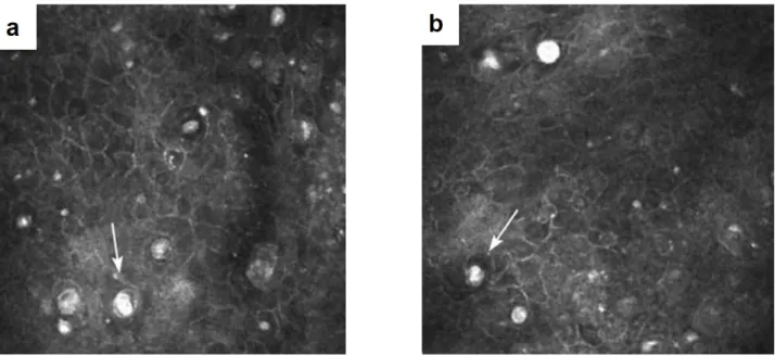
Figure 1.10 – Comparison of the central and peripheral cornea with in vivo confocal microscopy [28]. (a-c) Left to right: images from the central to peripheral stroma. On the first image (central cornea) keratocyte cells are easily distinguished, while in the periphery it gets more difficult to resolve them in the presence of the bright scattering background. White arrows show visible elongated fibers. (d,e) Left and right: central and peripheral endothelium, respectively.
18 Chapter 1. Ocular surface structures, diseases and diagnostics in clinics
As well as the central cornea, these zones can be affected by infectious, immunological dis-eases, etc. It is important to know the normal structure of the corneal periphery (together with the differences comparing to the central zone), because it allows to distinguish the abnormal conditions, requiring treatment. It is known that the central cornea is optically superior to the peripheral region [28]. Epithelial cell densities in the corneal periphery do not show significant differences comparing to the center. However, this is not true for the stromal keratocytes, which have a significantly denser population in the central cornea. Lamellae of the peripheral cornea are more disorganized (in terms of arrangement or/and size of the fibrils), which leads to an increased scattering from the background and a visible whiteness in the image (figure 1.10). Regarding endothelium, although cells are hexagonal in both regions, the heteromor-phism (variability in shape) is greater in the periphery. Moreover, peripheral cell counts give higher numbers [29].
1.1.3
Limbus
Limbus is a 1 - 1.5 mm transitional zone between the corneal periphery and sclera (figure 1.11). This is a specific and unique area, hosting a population of stem cells within the radial stromal ridges, called palisades of Vogt (POV). POV measure about 30 µm in width. Cells generated here on a regular basis replace epithelial cells of the whole cornea. Limbal zone is highly innervated, vascularised, and protected from the potential damage of ultraviolet light by the presence of melanin pigmentation.
Figure 1.11 – Limbus. (a) Slit lamp macro image of the human eye. Blue circle depicts the location of the limbus. (b) Cross-sectional conventional OCT image of the anterior human eye, showing location of the limbus. Adapted from [30]. (c) Electron microscopy image of the limbal palisades of Vogt (POV), adapted from [31]. Image magnification × 77. Epithelium was partly removed. POV appear to taper down toward the cornea. (d) Limbus with POV (black arrows) and vasculature viewed with a slit lamp, from [32]. (e) Cross-sectional image of the in vivo human limbus, obtained using Ultra-high resolution (UHR) OCT with red arrows emphasizing the POV [33]. (f) En face in vivo confocal microscopy image of POV from [34]. FOV = 400 µm.
1.2. Ocular surface disorders and diagnostics in clinics 19
1.1.4
Sclera
Sclera is the very peripheral part of the anterior eye, which, like the cornea, consists almost entirely of collagen fibrils. However, contrary to the cornea, these fibrils are more varying in size, shorter and more randomly organized, which explains the visible white opacification of the sclera. Bulk of the sclera is mostly avascular and accellular. Sclera serves as a strong coating for the intraocular structures, protecting against mechanical stresses induced by the eye movements (muscles responsible for eye motion are connected to the sclera tissue) and injuries. It also helps to maintain intraocular pressure.
1.1.5
Bulbar conjunctiva
Bulbar conjunctiva is a thin semi-transparent membrane that covers the surface of the eye from the sclera to the edge of the cornea. At the surface it has 6 layers of epithelium, and beneath, the conjunctival stroma with the collagen fibrils, fibroblast cells and a vascular system. The blood stream supplying the limbus with nutrients comes principally from the anterior ciliary arteries [16]. Conjunctiva serves as a barrier at the surface of the eyeball, which protects against the invasion of chemical, physical and biological agents. Detection of the infection results in the triggering of an inflammatory reaction - blood vessels of the conjunctiva become enlarged and consequently the blood flow increases (hyperaemia).
1.2
Ocular surface disorders and diagnostics in clinics
1.2.1
Global scope of ocular surface disorders
As we have seen from the previous section, the ocular surface is a highly-sophisticated system. A small malfunction in any part of it may lead to a broad range of potentially blinding corneal disorders: degenerative (keratoconus), inherited or infectious (bacterial, viral and fungal ker-atitis). These and many other conditions frequently lead to a loss of vision (4th leading cause of blindness worldwide [35]), making 1.5 to 2.0 million people unilaterally blind every year. Taking into account that the largest corneal blindness burden falls on the developing countries (more than 90% of the affected population) [36], cost-effective disease prevention through early diagnosis and treatment, and through public health programs is preferable over costly surgical interventions [37]. In this section we will have a look at a few selected examples of the challeng-ing and spread in population diseases. We will see that, while some ocular conditions can be successfully treated at any stage of the disease with a general antimicrobial medication, others require an early, precise and fast diagnosis. On the way, we will explore techniques and devices, used in modern clinical diagnostics.
1.2.2
Dry eye disease
Dry eye is a highly prevalent condition, which affects up to 11% of people 30–60 years of age and 15% of those over 65 years of age. The disease is more common in women than men (2:1) and the prevalence further increases with age. Basically, dry eye leads to a low quality of tear film, which fails to constantly cover the epithelium, leading to a loss of the epithelial cells. This can be due to the fast tear film evaporation, caused by its low osmolarity or, generally, because
20 Chapter 1. Ocular surface structures, diseases and diagnostics in clinics
of the small tear film production from the meibomian and lacrimal glands. Patients having a dry eye feel dryness, foreign body sensation, see with a decreased contrast, have fluctuation in a quality of vision and photophobia. The most common first line treatment is the daily use of the artificial tears. Medical doctors rely on several techniques to diagnose dry eye.
Schirmer test
In this test, a strip of filter paper is placed on the lower eyelid margin without anaesthesia. After 5 minutes, the strip is removed, and the amount of wetting is measured in millimeters (figure 1.12). Although this test is used frequently, it has been found to lack accuracy and reproducibility: the same person’s test results taken at the same time each day for several days can fluctuate widely, and the mean Schirmer test results for normal individuals have been reported to range from 8.1 mm to 33.1 mm. As such, many ophthalmologists avoid using this test.
Figure 1.12 – Methods in dry eye diagnosis. (a) Schirmer test strips with millimiter markings. Blue is used to facilitate measurement of tear wetting. Adapted from [16]. (b,c) Slit lamp macro photographs with fluorescein staining of normal subject (left) and dry eye patient with Sj ¨ogren syndrome (right), from [16]. (d-f) Tear film interference patterns, obtained
with a tearscope (adapted from [38]). According to the accepted classification table [39], lipid thickness is normal in a closed meshwork pattern in (a), and is slightly increased in the wave patterns in (e) and (f). It should be noted that the tear film thickness can vary in the normal human eyes, depending on the time after the last blink, preceded duration of the eye closure, etc. Therefore, a precise methodology is required for a successful use of the instrument.
Ocular surface staining with fluorescein
Another way to estimate the tear film quality is to put a fluorescent dye on top of the tear film. Fluorescein cannot penetrate into the uniform corneal epithelium, instead the corneal surface is stained, whenever there is a disruption in the cell-to-cell junctions. Therefore, fluorescein
1.2. Ocular surface disorders and diagnostics in clinics 21
highlights any part of the ocular surface, where the epithelium was damaged. Visible contrast spots in the inferior human eye can point to a potential dry eye disease (figure 1.12).
Measurement of tear break-up time (TBUT) with fluorescein
With fluorescein one can also evaluate the tear film stability by measuring the time interval between a complete blink and the first appearance of a dry spot. Like the Schirmer test, the TBUT test has been criticized as being unreliable and not reproducible. Many factors may lead to its non-reproducibility, including the volume of the fluorescein administered. Despite this unreliability, it is generally agreed that a TBUT of less than 10 seconds suggests tear film instability, and less than 5 seconds suggests definite dry eye (figure 1.12).
Tearscope
Recently introduced, Tearscope [39] allows to examine tear film by looking at the interference pattern on the surface of the eye, caused by the reflection from the thin lipid layer (figure 1.12). Following the Guillon classification [39], each pattern can be matched to the corresponding lipid thickness. Tearscope just recently entered into the clinical practice, therefore more studies are required to confirm correlation between the lipid layer measurements and the dry eye disease. Nevertheless, already now it is seen as a promising device with a potential for a reliable and quantitative diagnosis.
1.2.3
Fuch’s endothelial dystrophy (FECD)
Fuch’s is by far the most common corneal dystrophy to require keratoplasty (corneal trans-plantation). In general, the lifetime risk of FECD is about 0.1 %, however it can rise to 50% with unfavourable genetics [19]. The disease is 2.5 times more likely to develop in women than men. Fuch’s dystrophy manifests itself by the presence of the overgrown excrescences (called guttae) of descement’s membrane in the endothelium. That leads to a loss of endothelial cells, and subsequent stromal and epithelial corneal edema. As endothelium stops properly pumping the liquid from the cornea, the latter frequently swells overnight, which leads to blurring of vision during the morning hours. Other symptoms include pain, tearing, and oversensitivity to light. In order to diagnose FECD, instruments that can view endothelial cell mosaic are used, including slit lamp biomicroscope, confocal and specular microscopies (figure 1.13). FECD diagnosis is made following the findings of low counted endothelial cell density and irregular cell shapes (figure 1.13).
1.2.4
Microbial Keratitis
Microbial keratitis is a common, potentially sight-threatening ocular infection caused by the bacteria, viruses, fungi, or parasites. It is a clinical challenge to distinguish microbial keratitis from other noninfectious inflammatory conditions of the cornea resulting from trauma, hyper-sensitivity, etc. Time constraint makes this challenge even more difficult, as frequently only the correct diagnosis at the very earliest stage of the disease development can lead to a successful recovery without the negative consequences for vision. One example is Acanthamoeba keratitis, which affects 1.2 to 3 million people per year [42], mostly contact lens wearers. At the early
22 Chapter 1. Ocular surface structures, diseases and diagnostics in clinics
Figure 1.13 – Diagnostic methods of Fuch’s endothelial dystrophy. (a,b) With careful aligning, slit lamp biomicroscope can be used to visualize cellular mosaic in normal subjects (a) and Fuch’s dystrophy patients (b), adapted from [10]. Magnification: × 40. (c,d) Specular microscopy images of normal (c) and diseased (d) endothelium from [40]. (e,f) In vivo confocal microscopy data from normal subject (e) and patient with the disease (f) [41].
Figure 1.14 – Confocal microscopy in diagnosis of Acanthamoeba keratitis. Characteristic round 20
µm cysts, located in epithelium, are clearly visible.
stages neither the micro-organism, nor its cysts (measuring 11 - 15 µm) can be seen with a routinely used slit lamp biomicroscopy, due to its low resolution. In this case a conventional diagnosis procedure includes collection of scrappings from the ocular surface, followed by the several week growth of biological cultures and, eventually, histology. This is a long process, and even when it is done, the successful detection rate is low. In this situation one could think
1.2. Ocular surface disorders and diagnostics in clinics 23
about a possibility of prescribing the general broad-spectrum antibiotic for removing the mi-croorganism of the unknown nature. Unfortunately, general anti-microbial agents were found to be unable to eliminate both the trophozoite and cystic forms [43], and targeted medical treatment is needed. A recently adopted in clinics in vivo confocal microscope (IVCM) became the first in vivo imaging tool to cope with this problem and reliably resolve the cysts [18, 44] (figure 1.14).
1.2.5
Keratoconus
Keratoconus is a disorder characterized by the progressive corneal steepening, resulting in vision blurring, doubling astigmatism and over-sensitivity to light. Other symptoms are central corneal thinning and deformation of the Bowman’s layer. Both genetic and environmental processes are likely to be involved in pathogenesis. The signs of keratoconus can be revealed with a clinical Optical coherence tomography (OCT), which provides a high-resolution cross-sectional (side) view of the anterior eye. More precise corneal shape analysis is done with the corneal topographers (keratography) (figure 1.15).
Figure 1.15 – Diagnosis of keratoconus. (a-b) Normal (up) and keratoconic (bottom) eye screened with OCT, adapted from [45, 46]. Central corneal thinning is apparent. (c-d) Keratograph measurements in keratoconic eye from [47].
1.2.6
Diabetes
Diabetes is a disease characterized by a high blood sugar levels over a prolonged period. As of 2017, an estimated 425 million people had diabetes worldwide [48]. In non-emergency cases symptoms include unintended weight loss, blurred vision, headache, fatigue, slow healing of cuts, and itchy skin. One more symptom, associated with diabetes, is a progressive loss of nerves through the entire body. Interestingly, as the cornea is transparent and the most innervated tissue in the human body, it is a perfect candidate for reliably monitoring progress in diabetic
24 Chapter 1. Ocular surface structures, diseases and diagnostics in clinics
disease. Recent confocal microscopy studies demonstrated the correlation between the severity of diabetes and the sub-basal nerve density in the cornea (figure 1.16) [49].
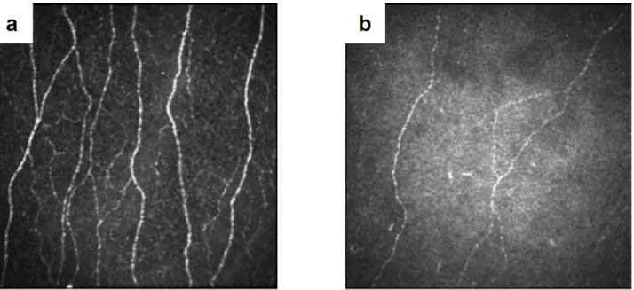
Figure 1.16 – Confocal microscopy recognizes difference in nerve densities in normal and diabetic subjects. (a) Healthy subject. (b) Patient with severe diabetic neuropathy. Adapted from [50].
1.2.7
Limbal stem cell deficiency
Limbal stem cell deficiency (LSCD) is referred to the condition of losing the stem cell population [16]. This can be caused by the damage to the limbus through thermal, chemical burns or even sun ultraviolet (UV) light, from which the limbus is typically protected with the eyelids. Cornea affected with LSCD becomes limited in its ability to repopulate the epithelium, which leads to the clinical symptoms of redness, irritation, photophobia, and decreased vision. On examination, slit lamp and confocal microscopy findings demonstrate the loss of Palisades of Vogt (figure 1.17) [51].
1.2.8
Conjunctivitis
Conjunctivitis is an inflammation of the outer white part of the eye. Beyond the visible redness, the frequent symptoms are the pain, itchiness, swelling. It is a well-spread condition, which contributes to an approximately 1% of the primary eye care visits. Typically, conjunctivitis is not severe and patients recover within one or two weeks. Nevertheless, depending on the conjunctivitis type (allergic, bacterial, viral etc.) the recovery may take longer and even may require months or years of prescripted medication use. Typical screening procedure involves slit lamp exam (figure 1.18), and typical medication are the topical antibiotic drops.
1.2. Ocular surface disorders and diagnostics in clinics 25
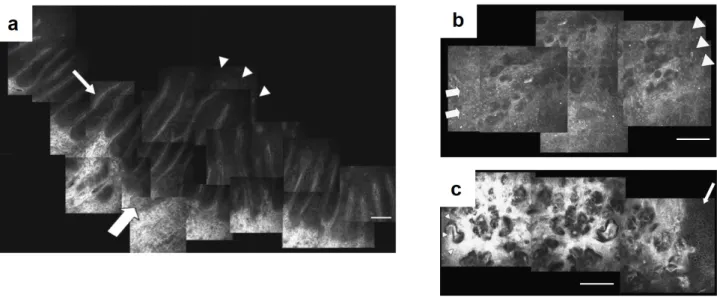
Figure 1.17 – Confocal microscopy based diagnosis of limbal stem cell deficiency (a) Healthy subject with the clear Palisades of Vogt in limbus. (b-c) Superficial (b) and deep epithelium (c) limbal section in patient with LSCD. Palisades of Vogt are lost, limbal epithelial architecture appears irregular. Corneal side is indicated by the arrows, while the conjunctival side by the arrowheads. Bar = 100 µm. Adapted from [51].
Figure 1.18 – Slit lamp examination of conjunctivitis. (a-b) Images of patient with a swelled conjunc-tiva, caused by the allergic conjunctivitis from [16]. (c) High-resolution view of vessels with the slit lamp. It is useful for examining the vessel structure and shape (elevations) of the conjunctiva. Adapted from [10].
CHAPTER
2
State of the art and emerging methods for ocular surface imaging
Table of contents
2.1 Brief history of ocular surface imaging methods . . . 28 2.2 Light-tissue interaction in the cornea . . . 29 2.3 Slit lamp biomicroscopy . . . 30 2.4 Specular microscopy . . . 32 2.5 Confocal microscopy . . . 33 2.5.1 Non-contact confocal microscopy . . . 35 2.5.2 Image stitching into a large FOV . . . 36 2.5.3 3D corneal images . . . 37 2.5.4 Confocal microscopy + OCT . . . 37 2.6 Optical coherence tomography . . . 38 2.6.1 Spectral-domain OCT (SDOCT) . . . 39 Ultrahigh-resolution SDOCT . . . 41 2.6.2 Swept-source (SSOCT) . . . 42 2.6.3 Time-domain full-field OCT (FFOCT) . . . 43 FFOCT applications . . . 47
28 Chapter 2. State of the art and emerging methods for ocular surface imaging
2.1
Brief history of ocular surface imaging methods
For more than a century light played an important role in eye disease diagnosis. Initially, this history started from the Fundus photography for imaging the retina. In 1851, Hermann von Helmholtz introduced the Ophthalmoscope. Later, in 1911 Alvar Gullstrand presented the first device, which opened a door to imaging of the entire eye from the retina to the cornea [52]. This device was the slit lamp microscope. After more than 50 years it is still considered to be the most universal and the most commonly used golden standard instrument. Despite its relatively simple design, it was incredibly helpful to ophthalmology specialists, providing a lot of information both about the global and local (up to cellular level) view of the eye. This information was used to understand, diagnose and come up with the strategies to address the majority of ocular conditions. Nevertheless, many diseases were yet to be diagnosed with more precise methods.
In 1974 David Maurice developed the first specular microscope to visualize the endothelium at a high magnification [9]. A good contrast, undisturbed by reflection from other corneal layers, together with a high resolution allowed to quantify cell changes associated with Fuch’s endothelial dystrophy and other diseases. Unfortunately, in order to obtain the clear images, the cornea must be transparent (no corneal edema, etc). As another limitation, this instrument did not permit optical sectioning, which made the corneal layers from different depths overlap in one image. Nevertheless, the specular microscope is widely used up to the present day with its advantages being the universality and low-cost. Soon after the creation of the first specular microscope, it was improved by Maurice through applying a confocal approach, patented by Marvin Minsky in 1955. This resulted in the enhanced resolution and contrast, and allowed to obtain the fine optical sectioned images from the endothelium and keratocytes. The next years resulted in a vast improvement in terms of speed and image quality, leading to the in
vivo confocal microscope (IVCM) - today the state of the art tool (in terms of resolution) for
diagnosis through the entire corneal thickness.
The most recent revolution in corneal imaging (and, in fact, the whole eye imaging) happened with the invention of optical coherence tomography (OCT) [1, 53]. Previously described specu-lar and confocal microscopes demonstrated impressive celluspecu-lar resolution, which was, however, achieved at a cost of shrinking the visible field to just half of a millimiter. The OCT provided an alternative view on the cornea with a large cross-sectional field, covering the whole anterior eye, together with a high axial resolution. That view was widely appreciated by the ophthal-mologists as, among many advantages, it provided a reliable way to quantify corneal thickness and iridocorneal angle (according to the name, it is an angle between the cornea and iris). Today OCT is an important part of the routine eye examination, and the technology continues to evolve. One of the recent advancements shows the ability to image cornea with a cell-detail
2.2. Light-tissue interaction in the cornea 29
resolution with an en face 1 - 2 mm field of view. Technology behind the images is called in
vivo time-domain full-field OCT and was developed in a course of this thesis project [3]. It
will be explicitly covered in the next chapter, while this chapter will explain the general tech-nical principles underlying the above mentioned devices. We will check their capabilities and limitations related to the ocular surface imaging.
2.2
Light-tissue interaction in the cornea
In order to obtain images of the cornea, instruments should detect the light, which interacted with it. Therefore, before, we move on to the description of the instruments, it is useful to understand, how corneal tissue interacts with the light. As we know from the previous chapter, the cornea consists of multiple layers.
The accellular layers (basement, Descemet’s membranes and Bowman’s layer) are very thin, constituting less than 4% of the total thickness. They consist of the collageneous tissue like stroma, therefore light scattering from them is minimal. On the other hand, the epithelium is about 50 µm deep (or 10% of the corneal thickness), nevertheless it is still transparent, due to another mechanism - strong homogeneity of the refractive index of all the constituent cells [54].
Figure 2.1 – Corneal transmission spectrum [6, 54]
Stroma is the thickest part of the cornea (about 460 µm or 90% of the total thickness). It is not homogeneous, but keeps transparency, because of the special arrangement of the stromal collagen, which permits only the certain distances between the neighbouring fibers and only the certain fiber diameters. The way it works is the following. When the light electromagnetic wave is incident on the stroma, it excites the electrons in the fibrils. Each excited electron oscillates and gives rise to the secondary electromagnetic waves, which propagate in the tissue in all the directions. Waves scattered from one fiber, superpose forming a cylindrical wave, which has the same axis as a collagen fibril. The cylindrical waves radially propagate from each fiber and interfere with each other. The interesting point is (and it was demonstrated theoretically, see [24]) that, under certain conditions of fiber diameters and distances between
30 Chapter 2. State of the art and emerging methods for ocular surface imaging
the fibers, these secondary cylindrical waves interfere in a way that they cancel out for all the directions except the forward. Exactly this fiber arrangement is found in the live cornea. As a result, what happens, is that almost all the incoming radiation to the cornea is completely scattered, but the scattered waves interfere, transferring all the energy only in the forward direction towards the retina.
In this model we looked only at the stromal fibrils, however stromal body also contains a large number of cells (keratocytes), which constitute 15% of the stromal volume [55]. The cell bodies are thin in the direction of light and are sparcely distributed, nevertheless it is thought to be insufficient to suppress the backscattering. As was found [25, 26], the keratocytes contain special molecules, which can adapt the refractive index of the cell cytoplasm to better match the surrounding and, thus, limit the scattering. On the confocal microscopy keratocyte nuclei is bright, while the cell membrane is dim or completely invisible.
While the reflection from inside of the cornea is very weak, the reflection from the interfaces of the cornea with the adjacent tissues is not negligible. Given that the refractive index of the cornea is 1.376, of the tear film - 1.336, of the aqueous humour - 1.336 and of the air - 1.0, it is easy to calculate from the Fresnel equations that the largest reflection is happening at the first air-tear interface (2% of the total light incident on the eye). Next tear-surface epithelium reflection gives just about 0.02%. Endothelium-aqueous humour interface at the inner end of the cornea also gives about 0.02%. While the last two numbers may seem insignificant, they give a lot of backreflected light comparing to the very weakly scattering cornea. This is confirmed in the confocal microscopy, which gives the bright and saturating images from the endothelium and surface epithelium, and relatively dark from the stroma.
To conclude, everything in the corneal structure is built with a focus on the transparency and forward scattering. This leads to an optically clear performance in the broad spectral window (figure 2.1), important for our vision. From the point of corneal microscopy, it means that the backscattered/backreflected signal and contrast between the adjacent tissues is very low, which makes corneal visualization difficult. On another hand, the corneal transparency is positive for microscopy too, because we can image through the entire corneal depth without going into the detail of challenging inverse scattering problems.
2.3
Slit lamp biomicroscopy
The slit lamp is the piece of equipment most frequently used by the ophthalmologist. Essentially it is a traditional microscope, which focuses the incoherent light on the object and collects the backreflected light to produce a magnified image. Nevertheless, there are several important design details, which make slit lamp so popular up to the present day. These details are focused on providing a doctor with all the flexibility to adapt the device on the fly to a particular clinical application.
First of all, the magnification of the instrument can be adjusted in a range from 5× to 50×, which correspondonds to a numerical aperture (NA) from 0.05 to 0.08. Illumination wavelength can be also chosen between the conventional white-light, blue-light (450 nm) (particularly useful, when eye is stained with a fluorescein) and others by using spectral filters. From the
2.3. Slit lamp biomicroscopy 31
Figure 2.2 – Diagnostics with slit lamp. (a) Schematics of the microscope and an example device photo from [56]. (b-c) Specular reflection configuration: incidence angle of illumination equals the angle of detection, useful for visualization of the endothelial cell mosaic. Illus-tration from [10]. Image from [57]. (d-e) Combined diffuse and tangential illuminations configuration: slit illumination is coming from the side, highlighting the elevations on the eye, while diffuse illumination enlightens the whole eye. Illustration from [10]. (f-g) optical sectioning configuration with the oblique angle and narrow slit, useful for acquiring OCT-like cross-sectional images. Illustration from [10]. Image from [57].
above parameters we can calculate the diffraction limited resolution achievable with the slit lamp according to the Rayleigh criterion 2.1:
![Figure 1.9 – Endothelium. (a) Cross-sectional electron microscopy image of the posterior cornea with endothelium [27]](https://thumb-eu.123doks.com/thumbv2/123doknet/2843256.69717/34.892.93.825.106.361/figure-endothelium-cross-sectional-electron-microscopy-posterior-endothelium.webp)

![Figure 2.6 – Stitched contact confocal microscopy images of sub-basal nerves. (a) Large field of view (16 mm 2 ) image of SNP, obtained by stitching 2541 images [62]](https://thumb-eu.123doks.com/thumbv2/123doknet/2843256.69717/53.892.70.790.634.939/figure-stitched-contact-confocal-microscopy-obtained-stitching-images.webp)