HAL Id: hal-02988292
https://hal.archives-ouvertes.fr/hal-02988292
Submitted on 4 Nov 2020
HAL is a multi-disciplinary open access
archive for the deposit and dissemination of
sci-entific research documents, whether they are
pub-lished or not. The documents may come from
teaching and research institutions in France or
abroad, or from public or private research centers.
L’archive ouverte pluridisciplinaire HAL, est
destinée au dépôt et à la diffusion de documents
scientifiques de niveau recherche, publiés ou non,
émanant des établissements d’enseignement et de
recherche français ou étrangers, des laboratoires
publics ou privés.
Efficient Decoding of Synchronized Colliding LoRa
Signals
Samira Abboud, Nancy Rachkidy, Alexandre Guitton
To cite this version:
Samira Abboud, Nancy Rachkidy, Alexandre Guitton. Efficient Decoding of Synchronized Colliding
LoRa Signals. IEEE VTC Spring, May 2020, Antwerp, Belgium. �hal-02988292�
arXiv:1902.05295v1 [cs.NI] 14 Feb 2019
Efficient Decoding of Synchronized Colliding LoRa
Signals
S
AMIRAA
BBOUD, N
ANCYE
LR
ACHKIDY, A
LEXANDREG
UITTONUniversité Clermont Auvergne, CNRS, LIMOS, F-63000 Clermont-Ferrand, France [email protected], [email protected], [email protected]
Abstract—In LoRa (Long Range), when a collision occurs in the network, each end-device has to retransmit its colliding frame, which reduces the throughput, and increases the energy con-sumption of the end-devices and the delay of the frames. In this paper, we propose an algorithm to decode colliding synchronized LoRa signals and thus improve the overall performance of the network. Indeed, we use successive transmissions of bitmaps by the end-devices to determine the correct symbols of each colliding frame, instead of retransmitting the whole frames. Simulation results show that our algorithm is able to significantly improve the overall throughput of LoRaWAN, and to decrease the energy consumption and the delay of the transmitters.
keywords - LoRa, LoRaWAN, collision cancellation, syn-chronized signals.
I. INTRODUCTION
Internet of Things (IoT) installations are becoming a reality and networks are being deployed to realize smart cities, such as transportation and vehicular traffic, healthcare, smart park-ing lot, surveillance systems and environmental monitorpark-ing applications [1]. For example, the climate conditions of the greenhouse or agricultural field, such as humidity, temperature, fires, earthquake, flooding, volcanoes, air pressure, water level, and soil moisture are monitored, where sensors may send data to the server over non-saturated network. Many of these IoT installations rely on Low-Power Wide-Area Network (LPWAN) technologies. These emerging technologies such as Long Range (LoRa) [2], Sigfox [3], RPMA [4] and Weight-less [5] enable power-efficient wireWeight-less communication over very long distances.
LoRa [2] is a widely deployed LPWAN technology and is considered by a large number of industries as a base for their IoT applications. LoRa uses orthogonal transmission settings (such as frequency, spreading factor) to reduce collisions. However, collisions cannot be totally avoided even when considering the capture effect. Current LoRa deployments use a default behaviour for retransmissions of colliding frames where each transmitter (e.g. the end-device) has to retransmit the whole colliding frame, which leads to reduce the overall throughput, and to increase the energy consumption and the delay. For these reasons, it is desirable to find a method for decoding the colliding signals, while decreasing the delay and the energy consumption of the transmitters, and improving the throughput.
In this paper, we consider non-saturated traffic conditions where the performance of both LoRaWAN and our pro-posed algorithm are analyzed in terms of the actual observed
throughput, delay and energy consumption. Besides, we con-sider the case of fully synchronized signals.
We show that overlapped symbols can be extracted by the receiver, although it is not possible to determine to which frame each symbol belongs. We propose an algorithm that aims to decode such superposed signals and to reduce the impact of collisions. The proposed algorithm relies on send-ing bitmaps by the end-devices in order to determine the correct symbols of the frames, instead of retransmitting the whole frames. This algorithm always succeeds to retrieve the frames from the superposed signals regardless of the number of colliding transmitters. Furthermore, the delay, the energy consumption, and the throughput are improved compared to LoRaWAN. Simulation results confirm the effectiveness of our proposed algorithm.
The rest of the paper is organized as follows. Section II presents a description of LoRa and LoRaWAN and some related works. Section III describes our proposed algorithm used for decoding fully synchronized signals. Section IV presents our simulation results. Finally, Sect. V concludes this paper.
II. STATE OF THE ART
In the following, we first describe the physical layer LoRa and the media access control (MAC) protocol LoRaWAN. Then we present some of the related works.
A. The LoRa physical layer
Long Range (LoRa) is a proprietary Chirp Spread Spectrum (CSS) modulation technique by Semtech [2]. LoRa main parameter is the Spreading Factor (SF) which has an influence on the transmission duration, the energy consumption, the ro-bustness and the communication range. SF defines the number of bits encoded into each symbol, and can vary between 7 and 12. Each symbol encodes one of2SF values, which cover the entire frequency band. When the maximum frequency of the band is reached, the frequency wraps around, and the increase in frequency starts again from the minimum frequency. A high spreading factor increases the Signal to Noise Ratio (SNR) and therefore the receiver sensitivity and the range of the signal. However, it reduces the transmission rate and thus increases the transmission duration and the energy consumption. The SFs in LoRa are usually considered orthogonal. Consequently, concurrent transmissions with different SF do not interfere with each other, and can be successfully decoded.
B. The LoRaWAN protocol
LoRaWAN [6] is an open-standard protocol which defines the MAC layer for LPWAN technology. LoRaWAN is de-signed by the LoRa Alliance [7] and operates on top of LoRa. LoRaWAN architecture is composed from end-devices that are connected to the network server through gateways which relay messages. LoRaWAN enables three classes of operation for devices: class A, class B, and class C. In class A, end-devices send data when ready and wait for an acknowledgment from the network server. Then, they switch to sleep mode to save energy until the next transmission. The delay between two transmissions has to be larger than 99 times the duration of the frame transmission in order to respect the duty cycle of 1%. In class B, which is optional, end-devices have additional scheduled receive periods to allow downlink communications with a bounded delay. In class C, which is also optional, end-devices are always active. For Europe region, the bandwidth of the channel is equal to 125 kHz for data rate 0 to data rate 5, and 250 kHz for data rate 6. SF7 is used for data rate 5 and data rate 6, and SF12 is used for data rate 0.
C. Related work on LoRa
Gateways in LoRa are able to decode superposed signals when they are sent on different SFs or on different channels. When signals are sent on the same channel and with the same SF, they risk to collide, unless the strongest signal is captured by the receiver. Since LoRa is a new technology, the amount of research on different aspects of both LoRa technology and LoRaWAN networks is limited. There have been a couple of works dealing with LoRaWAN collisions. Some researchers such as [8], [9], [10] and [11] have studied the collisions in LoRa and their impact on the throughput.
In [8], the authors presented an in-depth investigation of LoRaWAN frame collisions and the capture effect in particular through various experiments. They focused on correct recep-tion of data at the applicarecep-tion, instead of at the gateway, and they consider multi-gateways, and dense scenarios to obtain insight into collisions within actual networks, in order to inves-tigate under which circumstances collisions lead to frame loss. For example, their experiments showed that using multiple gateways instead of a single gateway increases the probability of receiving correct frames. Furthermore, they found that most frames hardly reached the more distant gateways, which is possibly due to the low spreading factor used most of the time. Collisions can also aggravate the situation, especially for the frames that use high SFs and required longer time on air.
In [9], the author proposed an analysis of packet collision and packet loss probabilities in LoRaWAN, and developed theoretical expressions for both of them. The author showed that his theoretical expressions are more accurate than a Poisson distributed process to describe the collisions.
In [10], the authors made a study regarding the CSS modulation technique. They show that some CSS symbols are not orthogonal. Their simulations show that the achievable range of the CSS technique is lower than an ultra-narrowband solution, but the robustness against interference is higher.
In [11], the authors provide an analysis and report experi-mental validation of the various performance metrics of the LoRa technology. The LoRa modulation is based on CSS, which enables low-quality oscillators in the end-device, and faster and more reliable synchronization. Therefore, LoRa seems to be a promising option for implementing communica-tion in many diverse IoT applicacommunica-tions. Authors first overviewed the features and analyzed the scalability of LoRa network. Then, they introduced setups of the performance measure-ments. Their results showed that using the transmit power of 14 dBm and the highest spreading factor of 12, more than 60% of the packets are received from the distance of 30 km on water. With the same configuration, they measured the performance of LoRa communication in mobile scenarios. Their results revealed that at around 40 km/h, the performance gets worse, because duration of the LoRa modulated symbol exceeds coherence time.
D. Related work on synchronized signals on LoRa
Few works have been done to study the collisions among synchronized signals in LoRa as in the following papers [12], [13] and [14].
In [12], the authors worked on constructing an efficient multi-hop network based on the sub-GHz LPWAN technology. They investigated the combination of LoRa and concurrent transmission (CT) which is a flooding protocol that considers synchronized packet collisions that happen when multiple relays perform immediate retransmissions at the same time. They found that, due to the time domain and frequency domain energy spreading effect, LoRa is robust to the packet collisions resulting from CT. They found the receiver performance under CT can be further improved by introducing timing offsets between the relaying packets. Therefore, they proposed a timing delay insertion method, the offset-CT method, that adds random timing delay before the packets while preventing the timing offset from diverging over the multi-hop network. Their experiments demonstrate the feasibility of CT-LoRa multi-hop network, and the performance improvement brought by the CT method. Their results showed that CT-LoRa experiences a high packet reception rate performance under the typical multiple-building area networks scenario. Moreover, they showed that LoRa survive the CT purely by capture effect which is considered in order to increase the probability of decoding colliding LoRa signals. However, if after taking into account the capture effect, the colliding signals are not decoded, they are considrered lost. In this paper, we decode LoRa colliding signals without considering the capture effect (although with the capture effect collisions are less encountered).
In [13], the authors have presented Choir which is a system that improves throughput and range of LPWANs in urban en-vironments. Choir proposed a novel approach that exploits the natural hardware offsets between low-power nodes to separate collisions from several LPWAN transmitters using a single-antenna LPWAN base station. Further, Choir allows groups of LoRaWAN sensor nodes with correlated data to reach the base station, despite being individually beyond communication
range. Choir directly improves the throughput of dense urban LPWANs by decoding transmissions from multiple nodes simultaneously with minimal coordination overhead. Choir recognizes that in practice, two signals who are synchronized in time can be separated by exploiting the natural hardware imperfections of the two radios. Specifically, signals from the two transmitters are likely to experience a small frequency offset, due to a difference in the frequency of their oscillators. This would result in the two chirps being slightly offset in frequency. Here are the differences between [13] and this paper: 1) While Choir allows collisions from multiple trans-mitters to be decoded, its gains are bounded and limited when increasing the number of nodes, and the possibility of over-lapping frequency offsets that increases with collisions from a larger number of transmitters. In this paper, we can manage a large number of transmitters by sending small bitmaps to save energy and further increase LoRa throughput. 2) If Choir fails to decode the synchronized colliding frames, it must retransmit the entire frames as in the traditional LoRaWAN protocol. Furthermore, if the collision continues to reproduce again between the same transmitters, it remains indecodable because the transmitters do not change their frequencies. In this paper, we rely on sending bitmaps and not to retransmit the entire frames. 3) Choir relies on the frequency offset to separate and decode synchronized interfering transmissions. In this paper, we did not consider frequencies. Consequently, we can combine both algorithms: Choir in first, and if it fails to decode colliding signals, our proposed algorithm comes in second to decode colliding signals.
In [14], the authors have proposed two algorithms to decode some cases of collisions of LoRa signals. The first algorithm is used when superposed signals are slightly desynchronized, and the second algorithm is used when superposed signals are com-pletely synchronized. Authors observe that the first algorithm is able to significantly increase the throughput, by decoding many collisions of two signals, and some collisions of three signals. On the other side, the second algorithm has improved the throughput, by decoding both signals when exactly two signals are colliding. The second algorithm requests any of the two colliding transmitters to retransmit its frame. Hence, when one frame is retransmitted, the algorithm is able to decode it, and to deduce the other colliding frame by elimination. The authors have considered the case of only two synchronized signals. In this paper, we are improving this by reducing the amount of data retransmitted, and by considering two or more synchronized signals.
III. PROPOSITIONS
In this section, we present our contributions for the physical and MAC layers. We propose an algorithm to decode super-posed signals that are fully synchronized. These signals are received on the same channel, with the same SF, and with the same received signal power. The proposed algorithm can not be applied on LoRaWAN protocol since most communications in LoRaWAN are desynchronized. Therefore, we introduce a new MAC layer which could be used on top of LoRa.
A. Physical algorithm
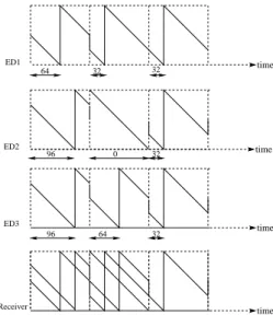
In this subsection, we consider the superposition of signals from transmitters that are fully synchronized as in [14]. Recall that papers [12] and [13] have ensured the feasibility of the synchronization among LoRa signals, by implementing a real LoRa system where transmissions were synchronized in time. Figure 1 shows an example of the reception of three fully synchronized signals under SF7. The figure shows that the signals start at the same time. Frame transmitted by end-device 1 (referred to ED1) is f1= (64, 32, 32), frame transmitted by ED2 is f2 = (96, 0, 32), and frame transmitted by ED3 is f3 = (96, 64, 32). In this figure, we can see that the receiver can extract symbols {64, 96} during the first symbol duration, symbols {0, 32, 64} during the second symbol duration, and symbol {32} during the third symbol duration.
However, the receiver is not able to determine to which frame each symbol belongs.
ED2 32 0 96 64 32 32 Receiver 64 32 96 ED3 ED1 time time time time
Fig. 1: Superposition of three synchronozed signals.
B. Our MAC protocol
In this subsection, we present and explain our MAC protocol used to decode synchronized colliding signals.
1) Description of MAC protocol and timing computation:
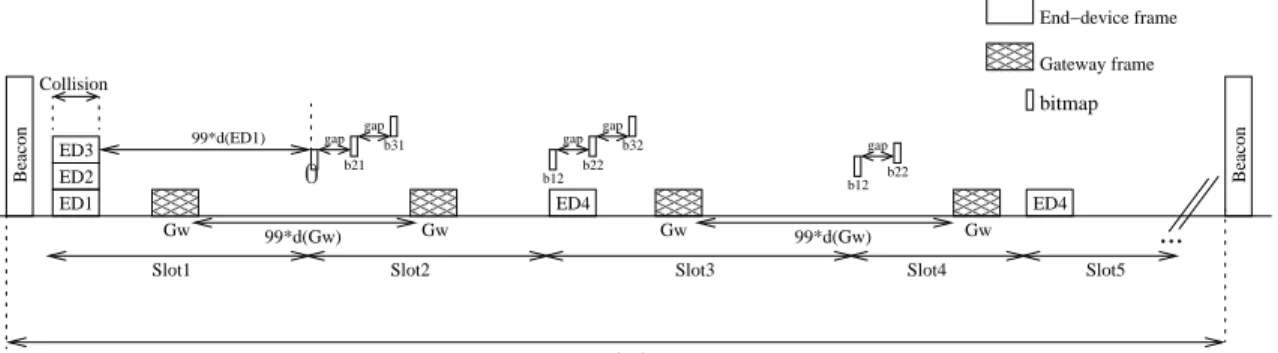
Figure 2 shows a MAC protocol implementing our proposed algorithm depicted for four end-devices. Beacons are sent by the gateway to synchronize the communications. We assume that the time is divided into slots and that transmissions on the same slot are fully synchronized. When a collision occurs between frames, the gateway stores all superposed symbols at each symbol duration. Then, it sends a frame built from these symbols. The gateway waits for bitmaps from the end-devices in order to decode the colliding frames, where each bit corresponds to the symbol chosen in the gateway frame. The gateway frame contains, in addition to the symbols, the order of the end-devices using an identifier on one symbol. As long as the frames sent by the end-devices are not yet decoded, the gateway sends a new frame, and the end-devices reply by sending new bitmaps.
00 00 00 11 11 11 00 00 00 11 11 11 000 000 000 111 111 111 000 000 000 111 111 111 00 00 00 11 11 11 Beacon Gateway frame bitmap End−device frame ED1 ED2 ED3 Gw b31 b21 Beacon period Gw ED4
...
gap gap ED4 b22 b32 b12 gap gap b12 b22 gap Gw 99*d(Gw) 99*d(Gw) Gw Beacon Collision Slot4 Slot5Slot1 Slot2 Slot3
99*d(ED1)
PSfrag replacements
0
Fig. 2: New MAC protocol depicted for the superposition of three synchronized signals.
To further describe our new proposed MAC protocol, we develop a timing computation model for the transmission process. Specifically, we consider separately the first and the subsequent transmission attempts.
The first frames transmission:The first transmission attempt of the devices frames is made on Slot1, where three end-devices ED1, ED2 and ED3 are initially fully synchronized, and sent their uplink frames at the same initial start time t0. This causes a collision at the gateway Gw which stores the superposed symbols, and sends a frame composed from these superposed symbols (See Section III-C for an example of the frame sent by the gateway).
The start time of the first gateway frame (t0Gw) is equal to the
initial start time of the EDs frames (t0) plus the duration dED (i.e time on air) of the EDs frames as follows: t0Gw = t0+dED
The bitmaps first transmission: Each bitmap of a given end-device is separated from the bitmap of the previous and the next end-devices by a small amount of time called guard interval (i.e gap). This guard time ensures that the bitmap of an end-device does not collide with the bitmap of another end-device, even when considering clock drifts.
By referring to Fig. 2, each end-device in Slot2 sends a bitmap in reply to the Gw frame. The bitmaps b11, b21, and b3
1 are sent by ED1, ED2 and ED3 respectively, after 99 times the duration of the frame transmission of ED1, ED2 and ED3. In addition, for each end-device x, its bitmap bx
i is delayed to avoid a collision with b(x−1)i and b (x+1)
i .
In other words, for an end-device x, the start time tbx i
of its bitmap number i should respect the following rule: (tb(x−1) i + db(x−1) i ) × (1 + ∆max) ≤ (tbx i) × (1 − ∆max) where db(x−1) i
is the time on air of the the previous bitmap, and ∆max is the maximum drift.
Hence, the start time tbx
i of a bitmap b x i is given by the following equation: tbx i = tb(x−1)i + db(x−1)i + gap with tb(x−1) i = tSlot+ (x − 2) × db(x−1) i + (x − 2) × gap where tSlot is the start time of the current slot.
Moreover, the duration of a slot is given by the following: dSlot= max(dED+ dGw, dbx
i × x+ gap × (x − 1) + dGw)
where dED is the duration of the end-device frame, and dGw is the duration of the gateway frame.
In relation to the slot duration, we set the start time of the last slot as follows: tSlotnmaxslots= dSlot×(nmaxslots − 1)
where nmaxslots is the maximum number of slots.
The bitmaps subsequent transmissions: The start time of a bitmap for the subsequent tranmissions is given by tbx
i = max(tbx(i−1)+ 100 × dbx(i−1), tGw+ 100 × dGw)
where the end-device should respect the duty cycle regulation, and should wait for the gateway frame before sending its bitmap bx
i with i >1.
Specific case: The general MAC algorithm contains slots where collisions between bitmaps and the frames of end-devices may occur. As shown in Slot3, the frame of ED4 collides with the bitmaps b12 and b22 related to ED1 and ED2 respectively. The gateway receives the bitmap b32 of ED3 and decodes it, while bitmaps b12 and b22 are not received. This leads ED1 and ED2 to retransmit their colliding bitmaps in Slot4. Also, ED4 (which corresponds to x= 4) retransmits its colliding frame as shown in Slot5 while respecting the duty cycle of 1% as follows: tEDx = tEDx−1 + 100 × dED. In
addition, the frame of a given end-device may collide with all the bitmaps of the other y end-devices that are sent on the same slot if: dED≥ y × dby
i + (y − 1) × gap
2) Description of our algorithm: Our algorithm described by Algorithm 1 is used to decode fully synchronized colliding signals for x transmitters (i.e end-devices), with x ≥2. In this paragraph, we explain how the receiver detects and decodes the colliding frames sent by x colliding end-devices. Indeed, when a collision occurs on the x EDs, the gateway can not decode the colliding frames, and is not able to determine to which frame each symbol belongs. Hence, the gateway considers that all the end-devices frames contain missing symbols, represented by * in Algorithm 1. Meantime, the gateway sends a frame built from the superposed symbols. At this step, each ED x replies to the gateway frame by sending a bitmap bxi (which corresponds to the bitmap number i). For each bit at position j in bxi, the algorithm checks the value of the bit. If bit is equal 1, then the algorithm replaces * in the frame of ED x with the current symbol j of the gateway frame. On the other hand, if the bit is equal0, the algorithm checks if the number of superposed symbols at the current position j is equal to 2. If it is the case, then the algorithm
replaces the * with the other current symbol at position j of the superposed symbols. In addition, the algorithm verifies if at position j, all the symbols of the EDs have been decoded (i.e not equal to *), and if there is still a missing symbol (i.e *) in a frame of another ED y. If it is the case, then the algorithm replaces the * in the symbol j of y by the remaining current symbol in the same position j of the superposed symbols. As long as there are missing symbols that can not be decoded by the gateway, the process is repeated until the decoding of all colliding signals. It is worth mentioning that this algorithm runs in polynomial time.
Algorithm 1 Decoding of fully synchronized superposed signals.
1: while a frame contains * do 2: the gateway sends a frame 3: for each end-device x do 4: x sends a bitmap bx
i
5: for each bit at position j in bx
i do
6: if bit= 1 then
7: symbol j of the frame fx ← symbol j
8: of the gateway frame
9: else if bit= 0 and the number of
10: superposed symbols at the current
11: position j is2 then
12: symbol j of fx ← the other symbol at
13: position j of the superposed symbols
14: end if
15: end for
16: for each end-device y do
17: for each symbol at position j do
18: if y6= x and all symbols j of fx 6= *
19: and the symbol j of fy= *
20: then
21: symbol j of fy ← the remaining
22: symbol j of the superposed symbols
23: end if
24: end for
25: end for
26: end for
27: end while
C. Guessing the frame
In this subsection, we show that the choice of symbols by the gateway has an impact on the number of bitmaps transmissions needed for each end-device. We refer to Fig. 1 to give an example of our proposed algorithm which is described by Algorithm 1.
Step 1: The gateway sends a frame with the following arbitrary set of symbols fG1 = (64, 0, 32). ED1 replies with the bitmap b11 = (1, 0, 1), ED2 replies with b21 = (0, 1, 1), and ED3 with b3
1 = (0, 0, 1). The current data frame of ED1 corresponds to f1= (64, ∗, 32), the current data frame of ED2 corresponds to f2= (96, 0, 32), and the current data frame of ED3 corresponds to f3= (96, ∗, 32).
Step 2: Since some of the frames of the end-devices still contain missing symbols that cannot be deduced by elimina-tion, the gateway sends another frame fG2= (96, 0, 32). ED1 replies with b12 = (0, 0, 1), and ED3 with b32 = (1, 0, 1). The updated frames of ED1 and ED3 remain the same as in Step
1, (i.e f1= (64, ∗, 32), f2= (96, 0, 32) and f3= (96, ∗, 32)). ED2 did not reply since its frame was decoded in Step 1.
Step 3: Since some of the frames of the end-devices still contain missing symbols that cannot be deduced by elimina-tion, the gateway sends another frame fG3 = (96, 32, 32). ED1 replies with b13 = (0, 1, 1), and ED3 with b33= (1, 0, 1). Now the updated frame of ED1 is f1= (64, 32, 32), and the updated frame of ED3 is f3 = (96, 64, 32). Note that the second symbol of f3 is decoded by deduction.
In this example, the average number of transmissions for each end-device is 2.33 bitmap transmissions.
Another example to decode the aforementioned colliding frames is the following:
Step1′:same as Step 1
Step2′:The gateway sends fG2′ = (96, 32, 32). ED1 replies with b12 = (0, 1, 1), and ED3 with b32 = (1, 0, 1). So the updated frames of ED1 and ED3 become f1 = (64, 32, 32), and f3= (96, 64, 32) respectively.
Here, the average number of bitmap transmissions for each end-device is 1.66 transmissions.
Therefore, the choice of the symbols by the gateway may impact the number of needed bitmap transmissions for each end-device. Hence, we propose a random selection of symbols that are not already sent by the gateway.
IV. SIMULATIONS AND RESULTS
In this section, we study and evaluate the performance of our proposed algorithms in terms of delay of successful decoding of colliding signals, energy consumption, and throughput.
A. Parameter settings
Simulations are carried out using our own simulator devel-oped in Java. We model a network with a single gateway, and x end-devices. We assume that all end-devices transmit with the same SF and on the same channel, and that their signals are received with almost the same strength at the gateway, i.e., no capture effect occurs. In our proposed algorithm, we assume that the time is divided into slots and that transmissions on the same slot are fully synchronized. We use both SF7 and SF12, as these two SFs have the highest and lowest data rates, re-spectively. The frame length is set to 30 bytes. We assume that collisions did not occur during the transmission of the bitmaps. Furthermore, we assume that the network is not saturated 1. We used nmaxslots= 1000, the maximum number of EDs x = 8, and the gap = 30 nanoseconds. Simulation results are obtained by averaging over one thousand samples.
1We chose the non-saturated case in order to better analyze the network performance. The saturated case will be handled in an extension of this paper.
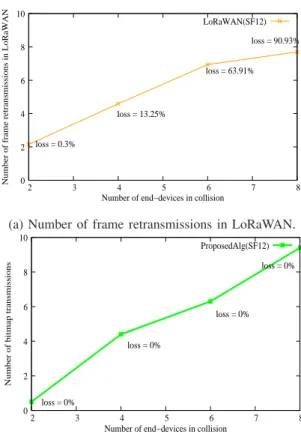
B. Number of bitmap transmissions in our protocol vs number of frame retransmissions in LoRaWAN
Figure 3.a) shows the number of retransmissions attempts in LoRaWAN with the percentage of frame loss. Figure 3.b) shows the number of necessary bitmaps for our proposed algorithm. Simulations are run using SF12. It is known that the number of collisions increases with the number of end-devices. This increase leads to an increase in the number of frame retransmissions in LoRaWAN, and to an increase in the number of necessary bitmaps needed to decode the colliding frames in our algorithm. The maximum number of retransmissions in LoRaWAN is set to 8 attempts by default [6]. Hence, after 8 retransmissions attempts in LoRaWAN, a loss might arise for the colliding frames. For example, we observe in Fig. 3.a), that for 8 colliding end-devices, we have almost 7.5 retransmissions per end-device with 90.93% of frame losses, while in Fig. 3.b), we have almost 9.5 bitmap transmissions per end-device without frame losses. Compared to [14], in the case of two synchronized signals and when the two frames of the two EDs collide, each end-device has in average 0.5 frame retransmissions. In LoRaWAN, each end-device has in average 2.15 frame retransmissions with 0.3% frame losses. Finally, in our proposed algorithm, each end-device has in average 0.5 bitmap transmissions (which is almost equivalent to 0.04 frame retransmissions, therefore twelve times better than [14]). Furthermore, the paper [14] does not handle the case of three or more colliding EDs.
C. Average delay
Figure 4 shows the evolution of the delay for the correct decoding of a frame in LoRaWAN and in our algorithm. The delay specifies the difference between the full decoding time of the frame by the gateway and the first time it is sent by the ED. We notice that the delay in LoRaWAN is greater than the delay in our algorithm. This is due to the transmission of short bitmaps in our algorithm instead of the retransmission of the whole frame in LoRaWAN. Since the size of a bitmap is smaller than that of a whole frame, the transmission time of a bitmap is much smaller than the transmission time of a whole frame, which leads to decrease the time needed to decode the colliding frame in our algorithm compared to LoRaWAN. For example, for 4 colliding end-devices with SF12, we observe a decrease in the delay of 30% in our algorithm compared to LoRaWAN. And for 4 colliding end-devices with SF7, we observe a decrease in the delay of 20% in our algorithm compared to LoRaWAN. Moreover, it is obvious that the delay for the correct decoding of a frame under SF12, is greater than that under SF7. This is because SF7 has the shortest time on air (i.e. the shortest frame time duration), while SF12 has the longest time on air.
D. Average energy consumption
Figure 5 shows the energy consumption calculated for an end-device after the full decoding of its frame by the gateway in both LoRaWAN and our proposed algorithm. It presents the consumed energy per useful bit as a function of the
LoRaWAN(SF12) 0 2 4 6 8 10 2 3 4 5 6 7 8 loss = 0.3% loss = 13.25% loss = 63.91% loss = 90.93%
Number of frame retransmissions in LoRaWAN
Number of end−devices in collision
(a) Number of frame retransmissions in LoRaWAN.
ProposedAlg(SF12) 0 2 4 6 8 10 2 3 4 5 6 7 8 loss = 0% loss = 0% loss = 0% loss = 0%
Number of bitmap transmissions
Number of end−devices in collision
(b) Number of bitmap transmissions in our algorithm.
Fig. 3: Average number of transmissions per end-device in both LoRaWAN and our proposed algorithm.
LoRaWAN(SF12) ProposedAlg(SF12) LoRaWAN(SF7) ProposedAlg(SF7) 100 200 300 400 500 600 700 800 900 2 3 4 5 6 7 8 Delay in seconds
Number of end−devices in collision Fig. 4: Delay of superposed signals.
number of colliding signals at two spreading factors (SF7 and SF12). It is observed that the consumed energy increases with the increase of the number of colliding signals, and also with the increase of SF. As known, the greater value of SF, the more time is taken to send a frame, so the more consumed energy is needed to transmit data. We refer to the following equation to compute the consumed energy per useful bit: Ebit = (
Pcons(Ptr)∗(NP ayload+NP+4.25)∗2SF
8∗P L∗BW ) [15],
transmission power. We set Ptrto 14 dBm. P L is the payload size set to 30 bytes. NP ayloadis the number of symbols used to transmit the payload and it is set to 30 for SF12 and 45 for SF7. NP is the preamble length set to 10. BW is the bandwidth set to 125000 Hz. We observe that the energy consumption for an end-device in LoRaWAN is much greater than that for an end-device in our algorithm. This is due to the transmission of bitmaps in our algorithm instead of the transmission of whole frames in LoRaWAN, which leads to decrease the energy consumption of the colliding frame. We observe with SF7 a decrease of almost 65% in the energy consumption in our algorithm in comparison with LoRaWAN, and we observe with SF12 a decrease of almost 78% in the energy consumption in our algorithm in comparison with LoRaWAN.
LoRaWAN(SF12) ProposedAlg(SF12) LoRaWAN(SF7) ProposedAlg(SF7) 0.25 0.5 1 2 4 8 16 32 64 2 3 4 5 6 7 8 Energy consumption in mJ
Number of end−devices in collision
Fig. 5: Energy consumption of superposed signals.
E. Average throughput
Figure 6 shows the evolution of the throughput computed for an end-device at the gateway side in both LoRaWAN and our proposed algorithm. The throughput is already small in LoRaWAN, and it decreases further with the number of end-devices and collisions. In Fig. 6, we observe that the throughput for an end-device in LoRaWAN is smaller than that for an end-device in our algorithm. This is due to the delay in LoRaWAN which is greater than the delay in our algorithm, and which leads to decrease LoRaWAN throughput compared to our algorithm. In addition, we have frame losses in LoRaWAN, which increase with the number of end-devices as already shown in Fig. 3.a). This increase leads to decrease further the throughput in LoRaWAN compared to our algo-rithm where no frame losses are present. For instance, for 8 colliding end-devices with SF12, we observe a gain of almost 95% in our algorithm compared to LoRaWAN. For 8 colliding end-devices with SF7, we observe a gain of almost 27% in our algorithm compared to LoRaWAN.
V. CONCLUSION
Collision is a factor that negatively impacts LoRaWAN throughput, which is already very limited (between 250 and 11000 bps). In this paper, we propose a collision resolution algorithm that enables to decode colliding frames in LoRa.
LoRaWAN(SF12) ProposedAlg(SF12) LoRaWAN(SF7) ProposedAlg(SF7) 0.015625 0.0625 0.25 1 4 16 64 2 3 4 5 6 7 8 Throughput in bps
Number of end−devices in collision Fig. 6: Throughput after a collision.
Our algorithm focuses on the case where end-devices are fully synchronized. The proposed algorithm relies on retransmitting bitmaps in reply to guesses from the gateway instead of the whole frame. Based on our simulation results, we show that the proposed algorithm is able to improve the throughput, by decoding the frames in collision. This algorithm is also able to reduce the energy consumption of the end-devices, and to decrease the delay needed to decode the frames. These results contributed to the development of a new MAC protocol based on LoRaWAN, relying on the proposed collision resolution algorithm, and surpassing LoRaWAN.
REFERENCES
[1] S. Talari, M. Shafie-khah, P. Siano, V. Loia, A. Tommasetti, and J. P. Catalão, “A review of smart cities based on the Internet of Things concept,” Energies, vol. 10, no. 4, p. 421, 2017.
[2] Semtech, “AN1200.22 LoRaTM Modulation Basics,”
https://www.semtech.com/uploads/documents/an1200.22.pdf. [3] Sigfox, http://www.sigfox.com.
[4] IngenuRPMA., http://www.ingenu.com/technology/rpma/. [5] W. O. Standard., http://www.weightless.org. Accessed:2015-11-07. [6] L. Alliance, “LoRaWAN specification,” LoRa Alliance, 2015. [7] https://www.lora-alliance.org/.
[8] A. Rahmadhani and F. Kuipers, “When LoRaWAN Frames Collide,” 2018, https://fernandokuipers.nl/papers/WiNTECH2018.pdf.
[9] G. Ferré, “Collision and packet loss analysis in a lorawan network,” in Signal Processing Conference (EUSIPCO), 2017 25th European. IEEE, 2017, pp. 2586–2590.
[10] B. Reynders and S. Pollin, “Chirp spread spectrum as a modulation technique for long range communication,” in Communications and Vehicular Technologies (SCVT), 2016 Symposium on. IEEE, 2016, pp. 1–5.
[11] J. Petäjäjärvi, K. Mikhaylov, M. Pettissalo, J. Janhunen, and J. Iinatti, “Performance of a low-power wide-area network based on LoRa technology: Doppler robustness, scalability, and coverage,” Interna-tional Journal of Distributed Sensor Networks, vol. 13, no. 3, p. 1550147717699412, 2017.
[12] C.-H. Liao, G. Zhu, D. Kuwabara, M. Suzuki, and H. Morikawa, “Multi-hop LoRa networks enabled by concurrent transmission,” IEEE Access, vol. 5, pp. 21 430–21 446, 2017.
[13] R. Eletreby, D. Zhang, S. Kumar, and O. Ya˘gan, “Empowering Low-Power Wide Area Networks in Urban Settings,” in Proceedings of the Conference of the ACM Special Interest Group on Data Communication. ACM, 2017, pp. 309–321.
[14] N. El Rachkidy, A. Guitton, and M. Kaneko, “Decoding Superposed LoRa Signals,” IEEE LCN, 2018.
[15] T. Bouguera, J. Diouris, J. Chaillout, R. Jaouadi, and G. Andrieux, “Energy Consumption Model for Sensor Nodes Based on LoRa and LoRaWAN.” Sensors (Basel, Switzerland), vol. 18, no. 7, 2018.