Publisher’s version / Version de l'éditeur:
2014 Oceans - St. John's, OCEANS 2014, 2014-09-14
READ THESE TERMS AND CONDITIONS CAREFULLY BEFORE USING THIS WEBSITE. https://nrc-publications.canada.ca/eng/copyright
Vous avez des questions? Nous pouvons vous aider. Pour communiquer directement avec un auteur, consultez la
première page de la revue dans laquelle son article a été publié afin de trouver ses coordonnées. Si vous n’arrivez pas à les repérer, communiquez avec nous à [email protected].
Questions? Contact the NRC Publications Archive team at
[email protected]. If you wish to email the authors directly, please see the first page of the publication for their contact information.
NRC Publications Archive
Archives des publications du CNRC
This publication could be one of several versions: author’s original, accepted manuscript or the publisher’s version. / La version de cette publication peut être l’une des suivantes : la version prépublication de l’auteur, la version acceptée du manuscrit ou la version de l’éditeur.
For the publisher’s version, please access the DOI link below./ Pour consulter la version de l’éditeur, utilisez le lien DOI ci-dessous.
https://doi.org/10.1109/OCEANS.2014.7003281
Access and use of this website and the material on it are subject to the Terms and Conditions set forth at
Numerical modelling complements physical testing in staged design of
ocean wave-driven pump
Boileau, Renee; Raman-Nair, Wayne; Graham, Michael
https://publications-cnrc.canada.ca/fra/droits
L’accès à ce site Web et l’utilisation de son contenu sont assujettis aux conditions présentées dans le site LISEZ CES CONDITIONS ATTENTIVEMENT AVANT D’UTILISER CE SITE WEB.
NRC Publications Record / Notice d'Archives des publications de CNRC:
https://nrc-publications.canada.ca/eng/view/object/?id=fd4e711c-6e83-4a00-8c27-781729e89fb8 https://publications-cnrc.canada.ca/fra/voir/objet/?id=fd4e711c-6e83-4a00-8c27-781729e89fb8Numerical modelling complements physical testing
in staged design of ocean wave-driven pump
Renee Boileau and Wayne Raman-Nair
National Research Council of Canada St. John’s, Canada
[email protected] [email protected]
Michael Graham
Burin Campus College of the North Atlantic
Burin, Canada [email protected]
Abstract—National Research Council Canada (NRC) is
col-laborating with College of the North Atlantic (CNA) to develop an ocean wave-driven pump to supply the CNA shore-based aquaculture centre in Lord’s Cove, Newfoundland. NRC pro-vides a combination of physical model testing under controlled laboratory conditions and computer simulation using numerical modelling tools developed at NRC and commercial software.
The CNA plans to demonstrate the sustainability of a shore-based aquaculture centre in the context of rural Newfoundland. The efficiency of the centre depends in part on its energy consumption, a major part of which is supplying seawater to a facility some distance from the ocean and above sea level. The development of a seawater supply pump driven by the power of ocean waves would reduce the electrical costs for the centre. The NRC is supporting a staged design program through numerical and physical model testing to select a robust design optimized for the local sea conditions at the Lord’s Cove mooring site.
The wave pump is inspired by designs for wave energy converters. But since wave energy converters have not converged on a single design, there are major risks and costs in designing a wave pump, from construction and testing of physical models for competing designs to mooring failure and potential loss of the device in the hurricane-force storms typical of southern Newfoundland. Using lessons learned in the energy sector, risks can be mitigated by systematically testing the behaviour and response of proposed concepts through a staged design program, starting from characterizing the hydrodynamic characteristics of a simplified model through progressively larger, more complex physical and numerical models used in functional tests. This approach systematically directs the design process toward a single prototype optimized for performance in specified wave conditions using scaled model tests in advance of the most costly stage of sea trials.
The goals of the staged design program for the CNA wave-driven pump are to
∙ evaluate various design concepts,
∙ select a design suited to the CNA mooring site, ∙ optimize the design for a typical sea state and
∙ specify a mooring robust enough to keep the platform
on station during the sometimes extreme sea states at Lord’s Cove.
The program began with characterization of the chosen mooring site outside Lord’s Cove. Processed wave buoy data from this site informed the estimation of mooring line loads using numerical tools developed by NRC and typical sea states on which to focus design optimization. In the second stage, a numerical tool
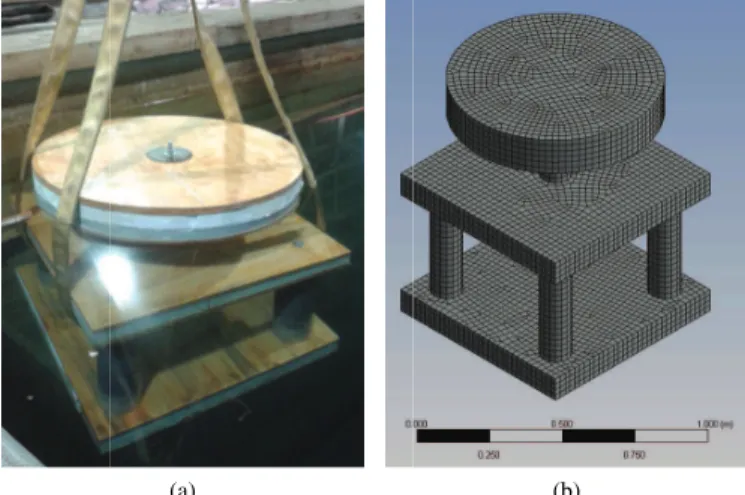
(a) (b)
Fig. 1. Hydrodynamic (non-functional) physical model (a), afloat, and corresponding numerical model (b), meshed, for one platform design concept
was developed to estimate pump output and validated against test results for a physical pump. In the third stage, various wave pump platform design concepts were evaluated based on estimation of hydrodynamic characteristics. The designs were characterized using a combination of physical model tests in the NRC 200-metre wave tank in St. John’s and computer simulations using Ansys Aqwa and Matlab. A sample pump platform design is shown as a scale model and a numerical mesh in Fig. 1.
In the fourth stage, which will precede a full-scale prototype deployment at sea, a design has been selected and an operational scale model wave pump platform has been tested in the NRC wave facilities. Numerical modelling is used to choose a mooring for the full-scale deployment.
In this staged design program, the use of physical model tests and computer simulation are complementary methods used alter-natively to solve potentially costly and time-consuming problems. A selection of the problems encountered in the design of the wave pump platform is presented along with a critique of the solutions applied by NRC to build confidence in a wave-driven pump design tailored for the CNA site.
Keywords—wave-powered pump, wave energy converter, shore-based aquaculture.
I. INTRODUCTION
National Research Council Canada (NRC) is working with College of the North Atlantic (CNA) to develop an ocean wave-driven pump under a Collaborative Research Agreement. The pump is needed to reduce the energy cost of supplying seawater to the CNA shore-based aquaculture centre in Lord’s Cove, Newfoundland. The pump is inspired by point-absorber type wave energy converters (WECs), which extract energy from the relative motion of a float riding over waves and the power take-off restricted by a mooring.
To assist in the design of the wave pump, NRC is providing a combination of physical model testing under controlled laboratory conditions and computer simulation using numerical modelling tools at NRC and commercial software (Ansys AqwaTM).
This paper describes how a staged design process using combinations of numerical and physical models has ensured steady progress toward a full scale prototype. It will demon-strate how a complementary approach overcomes design issues and the limitations of both methods.
A. Background
CNA plans to demonstrate the sustainability of a shore-based aquaculture centre in the context of rural Newfoundland. The efficiency of the centre depends in part on its energy consumption, a major part of which is supplying seawater to a facility some distance from the ocean and approximately 20 metres above sea level. The development of a seawater supply pump driven by the power of ocean waves would reduce the electrical costs for the centre.
As part of the development of the aquaculture centre, CNA has established the Wave Energy Research Centre (WERC), headquartered in the former fish plant in Lords Cove, Newfoundland (4652’43”N 5540’10”W). The purpose of the WERC is to conduct research on the use of ocean wave energy to supply sea water to land-based aquaculture [1].
The WERC site has six mooring sites (shown in Fig. 2) permitted under the Canadian Navigable Waters Protection Act. An acoustic wave and current profiler (AWAC) deployed 1.5 km offshore and a weather station within 30 m of the high tide mark continuously collect local data. In addition, the bathymetry of the harbour and its approaches has been mapped. The first project of the WERC is to develop a wave pump to be moored at Lord’s Cove. The specification for the wave pump includes minimum pressure head (to reach the elevation of the fish tanks) and minimum flow rate averaged over time to maintain the level in a reservoir tank in sea states typical for Lord’s Cove, which opens into the North Atlantic Ocean. The pump must also be robust enough to survive corrosion from sea water, operating with or mitigate biological fouling (e.g., mussel growth) and keep station or fail safe in hurricane conditions.
Wave energy converters have not converged on a single design [2]. There are major risks and costs in designing a wave pump, from construction and testing of physical models for competing designs to mooring failure and potential loss of the device in the hurricane-force storms typical of southern Newfoundland.
Fig. 2. Map of Wave Energy Research Centre sites at Lord’s Cove, Newfoundland
Using lessons learned by NASA and the energy industry, among other major engineering firms, risks can be mitigated by systematically testing the behaviour and response of pro-posed concepts through a staged design program, starting from characterizing the hydrodynamic characteristics of a simplified model through progressively larger, more complex physical and numerical models used in functional tests [3].
Realizing the risks implied by this innovative endeavour, NRC is applying a staged approach to this wave pump design process based on advice arising out of participation in the development of WEC testing guidelines for the International Electrotechnical Congress (IEC).
B. Scope
The following sections describe the staged design process for this wave pump and focusses on two key challenges: pre-dicting pump output from shaft loads and simulating reactions on a mooring for conceptual designs. A discussion on the efficacy of this staged approach is followed by a description of future work. This paper does not present the final design or test data.
II. ASTAGED DESIGN PROCESS
The NRC is supporting a staged design program through numerical and physical model testing to select a robust design optimized for the local sea conditions at the Lords Cove mooring site.
The goals of the design program for the CNA wave-driven pump are to:
∙ evaluate various design concepts,
∙ select a design suited to the CNA mooring site, ∙ optimize the design for a typical sea state and ∙ specify a mooring robust enough to keep the platform
on station during the sometimes extreme sea states at Lord’s Cove.
Since this is a completely new design, the design program has been broken into stages:
1) site characterization 2) numerical pump modelling
3) platform concept and mooring design evaluation 4) 1:5 scale functional model testing
5) full-scale design
6) field trial1 of a full-scale prototype
A general statement of work was developed in 2011. The specifics of each stage remain fluid, a characteristic of agile
project management [4]: the outputs from one stage guide the development of succeeding stages and iterations occur within stages. This approach systematically directs the design process toward a single prototype optimized for performance in specified wave conditions using scaled model tests and numerical modelling in advance of the most costly stage of sea trials.
To inform the design, Stage 1 was completed in 2012 with short-term characterization of the chosen mooring site outside Lord’s Cove. Processed wave buoy data from this site informed the estimation of mooring line loads using numerical tools developed by NRC and typical sea states on which to focus design optimization [5].
In Stage 2, completed in spring 2013, a numerical tool was developed to estimate pump output and compared against test results for a physical pump [6].
In Stage 3, various wave pump platform design concepts were evaluated based on estimations of hydrodynamic charac-teristics. The designs were characterized using a combination of physical model tests in the NRC 200-metre wave tank in St. John’s (fall 2013) and computer simulations using Ansys Aqwa and MatlabTM[7]. Platform response on moorings were predicted using a numerical tool developed for prior work by NRC [8].
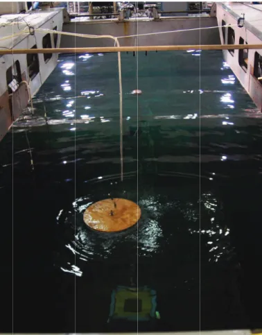
For Stage 4, a design was selected and an operational scale model wave pump platform was tested in the NRC wave facilities in May 2014 (Fig. 3, report pending).
Stage 5, work in progress summer 2014, is full scale design, which will precede a full-scale prototype deployment at sea.
In this staged design program, the use of physical model tests and computer simulation are complementary meth-ods used alternatively to solve potentially costly and time-consuming problems. The following two cases in point dissect two issues encountered in the design of the wave pump platform.
III. CASE1: LIMITATIONS OF A MATHEMATICAL PUMP MODEL
During Stage 2, a mathematical model was developed in MatlabTM
to predict the output of a double-acting wave pump based on the one-dimensional equation of motion of a piston under the action of applied wave forces and velocity-dependent frictional resistance.
1full scale test in real world environment (i.e., at sea)
Fig. 3. Functional scale model in NRC (St. John’s) wave tank (Stage 4)
This mathematical model, shown in Fig. 4a, can solve for piston motion, cylinder pressures and flow rate given the applied force acting on the piston rod and a set of parameters (pump dimensions, fluid characteristics and test conditions) as inputs. These inputs are used to calculate parameters that characterize the pump’s response in simulated waves.
In this stage, a pump was driven by a linear actuator: force, pressures and flow data were measured. For comparison with test data, the numerical model solved for applied force, pressures and flow rate as a function of piston position. Difficulties arose in estimating friction for the real pump [6]. A sensitivity study of the five inputs listed in Table I determined that the flow rate predictions of such a model are highly sensitive to estimates of frictional resistance. Frictional resistance is calculated based on the clearance between the piston seal and the pump wall, a dimension that proved impractical to measure accurately.
TABLE I. NUMERICAL MODEL SENSITIVITY TO ACCURACY OF INPUT PARAMETERS
parameter effect
measured
piston diameter linear piston length negligible
inferred
piston clearance exponential coulomb friction negligible orifice flow coefficient linear
F(t) outlet pout inlet pin x(t) p1 p2 q q closed closed (upstroke) (a) (b)
Fig. 4. Diagram of mathematical model for a double-acting pump (a) and physical model (b)
The mathematical model was run with inputs for the real pump shown in Fig. 4b and compared against data from the pump driven by a linear actuator: applied force on the shaft, piston motion, inlet and outlet line pressures (upper and lower cylinder) and flow rate were measured. The physical pump exhibited high friction due to tight-fitting seals and an over-constrained mount that prevented self-alignment. The resulting friction swamped other forces on the pump; despite attempts to estimate the friction coefficient from a subset of the tests, the results were inconsistent. Without a reliable estimate for the friction coefficient, the mathematical model (Fig. 5) could not be calibrated.
The attempt to develop this model revealed that key param-eters – notably friction coefficient (via piston clearance and, to a lesser extent, piston diameter) and orifice flow coefficient – are difficult to predict for a generic model at this early stage. These parameters are needed if the numerical model is to be useful in informing later stages, especially designing or selecting a pump.
It is concluded that the utility of this model is limited to predictions of flow rate for the idealized case of minimal frictional resistance and that the model be used only to estimate
0 1 2 3 4 5 6 7 8 9 10 −600 −400 −200 0 200 400 600
run Flow_H3_T5_S10_001 cvisc= 1600
time (s)
force(N)
applied (load cell) applied (model) weight viscous bernoulli m · a
Fig. 5. Relative contribution of friction to applied force using arbitrary coefficient to match data
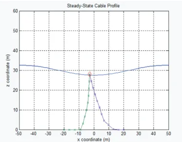
Fig. 6. Two-dimensional mooring simulation
maximum possible flow rate for a given regular wave.
IV. CASE2: ALTERNATIVE INPUTS FOR PREDICTING PLATFORM BEHAVIOUR ON A MOORING
During Stage 3, competing design concepts were evaluated using a numerical mooring model developed by NRC and adapted from a prior, federally-funded wave energy project [8]. The numerical model simulates motion and line loads for a rigid floating body in regular waves based on hydrodynamic inputs: a sample screenshot is shown in Fig. 6. Hydrodynamic characteristics of the platform concepts were predicted using Ansys Aqwa, with some comparison to physical test results.
The mooring system is numerically modelled by consid-ering the coupled dynamics of a floating platform and two mooring lines. The line dynamics are accounted for by using a lumped mass approximation and inter-connecting springs with stiffness calculated from the line properties. Wave forces are found from second order wave theory formulae and fluid loads on the mooring lines are applied using the Morison formulation.
This two-dimensional numerical model requires damping coefficients and added mass in sway, heave and roll as inputs for each platform. Ansys Aqwa can predict the hydrodynamic characteristics of a rigid body in regular waves across a range of periods: to run Aqwa, the three CNA platform concepts were translated from computer-aided drawings (CAD) to three-dimensional meshes in Ansys Design Modeler (Fig. 7).
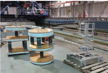
To validate the Ansys model, three scaled rigid hydrody-namic models corresponding to the platform concepts were fabricated and tested in the NRC clear water towing tank: the scale models are shown in Fig. 8. The wave tank tests provided data at the natural frequency of the physical model only, from which damping coefficients and added mass were calculated. Ansys and physical test results were compared only at the natural frequency for modes corresponding to the numerical model (surge, heave and roll).
While some physical test results agreed well with Ansys, surge damping coefficients and added mass derived from
Fig. 7. Mesh models for three platform concepts
Fig. 8. Hydrodynamic (non-functional) scale models
horizontal spring-driven tests failed to produce sensible results. Due to schedule constraints, the fault in the method was not determined, whether in post-analysis or the test itself; the Ansys Aqwa results were presumed reliable based on the correlation with non-spring-driven tests.
Following the natural frequency comparisons, hydrody-namic inputs for each of the shapes were predicted using Ansys Aqwa over a range of periods typical of Lord’s Cove sea states. The numerical mooring model was run with each set of inputs and three mooring designs (rope, chain and composite moorings) and produced animations of the platforms that responded to waves realistically. The numerical model results indicate that mooring loads were well within conservative safety margins for line strength in all cases.
V. DISCUSSION
This staged design program has circumvented several hur-dles through the use of both physical model tests and computer simulation. The two key issues presented here were overcome (sidestepped?) by taking advantage of complementary infor-mation available from test data and numerical predictions. Relying solely on either would have resulted in major delays and additional costs to solve problems unrelated to the design. At each stage of the design program, issues and their proposed solutions have been documented in detailed ”Dis-cussions” and ”Lessons learned” report sections. Some issues, such as sensor selection and model assembly problems, were
resolved at that stage; others were addressed with workarounds sufficient to achieve interim goals.
In both cases of arising issues described here, the results of the numerical models are limited by the quality of the inputs. In the Case 1, the numerical pump model is limited by pump characteristics that are unmeasurable with ordinary tools: predicting resistance is a common problem with the simplifications inherent in an analytical approach. As a result, this model is only useful for idealistic estimates of pump flow and we must rely on physical testing to provide realistic inputs. Physical testing is limited to predictions within the range of test conditions and by the type of scaling used.
In Case 2, the numerical mooring model relies on hydrody-namic characteristics that are most efficiently produced using commercial software. However, that software is limited by the analytical models on which it is based: Ansys Aqwa is a panel code and so solves the Laplace equations for added mass and damping, but neglects viscous effects. For this device, which operates in an environment dominated by waves (vs. current), the motion is sinusoidal and therefore dominated by accelerations, so viscous effects can be neglected and use of a panel code is appropriate.
Physical testing is useful for determining added mass and damping for a particular model. In this case, the physical tests simplified to fit this project’s schedule and budget were useful for a limited validation exercise, but had its own challenges: damping tests provided information about the natural frequen-cies only and introducing springs as a restoring force for the horizontal modes proved problematic.
By reviewing the work at each stage before proceeding to the next, the numerical pump model can be seen as a dead end to be removed from the critical path, while the mooring model can be used as a check without interfering with later work.
After four stages, the solutions applied by NRC in collabo-ration with CNA have resulted in a functional physical model. It is believed this WEC may be scaled to the mooring site using Froude scaling to approximate its performance. Using agile management, we progressed by maintaining focus on goals more than plans and having a clear concept of what the end product should be, while being fluid in specifying work packages.
A hallmark of a successful design project is knowing critical parameters well enough and at the right time, while avoiding unnecessarily onerous standards or ill-timed steps. The key is identifying these parameters and acceptable uncer-tainties and linking them to the appropriate stage of devel-opment. Guidelines such as those being developed under the IEC TC114 steer early developers toward appropriate levels of instrumentation and staged test programs.
NRC is renowned for highly accurate test protocols, data acquisition and analysis products; however, the acceptable uncertainty in results can and often should be lowered in early design stages when the goals are proof of concept and relative performance, not absolutes.
With the results from this test program, CNA is able to proceed with some confidence in designing a full-scale wave-driven pump design tailored for the CNA site.
VI. FUTURE WORK
Following the full scale design stage, CNA anticipates fabricating a prototype this winter for deployment at sea in spring 2015. Numerical modelling may be used to choose a full scale mooring based on predicted loads scaled from the tank tests and hydrodynamic inputs from Ansys Aqwa.
Issues arising from the limitations on numerical tools may be addressed in later projects with funding tied to the development of numerical tools and test procedures tailored for WEC testing.
In particular, NRC has a license for Ansys Aqwa with coupled cable dynamics: this commercial code could be used to solve the dynamics of a mooring system for a WEC, without external calculations, given further investment to develop a streamlined workflow.
The Wave Energy Research Centre continues to collect wave and weather data, not only to inform the current WEC development, but also to study wave propagation within the harbor using Aquaveo SMS 11.0 software and bathymetry and AWAC data. This will allow expansion of research at the centre to include simultaneous study of multiple WEC devices and facilitate the study of shore effects, such as storm-induced infrastructure damage and mitigation systems and shore-mounted WEC performance evaluations.
ACKNOWLEDGMENT
The authors would like to thank Research and Develop-ment Corporation of Newfoundland and Labrador (RDC) and Natural Sciences and Engineering Research Council of Canada (NSERC) for funding this work.
We are especially grateful to the local boaters in the community of Lord’s Cove for their assistance with deploy-ments and retrievals and without whom work would have been severely delayed due to loss of moored equipment in challenging sea states of the North Atlantic Ocean.
REFERENCES
[1] College of the North Atlantic. (2012, March) WERC CNA Education. Facebook profile. College of the North Atlantic. [Online]. Available: https://www.facebook.com/WERCCNA/info
[2] R. E. Harris, L. Johanning, and J. Wolfram, “Mooring systems for wave energy converters: A review of design issues and choices,” in 3rd Intl. Conference on Marine Renewable
Energy (MAREC 2004), Blythe, UK, 2004. [Online]. Available:
https://www.oreg.ca/web documents/mooringsystems.pdf
[3] B. Holmes, K. Nielsen, and S. Barrett, “Wave energy development & evaluation protocol,” in Proc. 7th European Wave & Tidal Energy
Conference, 2007.
[4] J. L. Ward, Dictionary of project management terms, 3rd ed. ESI International, 2008.
[5] R. Boileau, “Wave resource assessment for Lord’s Cove, Newfoundland – 2012 survey,” National Research Council Canada, Technical Report OCRE-TR-2013-008, January 2013.
[6] R. Boileau and W. Raman-Nair, “NRC wave pump tests for numerical model development,” National Research Council Canada, Technical Report OCRE-TR-2013-030, May 2013.
[7] ——, “CNA wave pump platform design concept evaluation: numerical modelling of floating moored bodies in regular sea states,” National Re-search Council Canada, Technical Report OCRE-TR-2013-043, Novem-ber 2013.
[8] W. Raman-Nair and R. Boileau, “Two-dimensional mooring dynamics for wave energy converters,” National Research Council Canada, Technical Report TR-2012-04, Jan. 2012.