Publisher’s version / Version de l'éditeur:
Student Report, 2010-12-01
READ THESE TERMS AND CONDITIONS CAREFULLY BEFORE USING THIS WEBSITE. https://nrc-publications.canada.ca/eng/copyright
Vous avez des questions? Nous pouvons vous aider. Pour communiquer directement avec un auteur, consultez la Questions? Contact the NRC Publications Archive team at
PublicationsArchive-ArchivesPublications@nrc-cnrc.gc.ca. If you wish to email the authors directly, please see the first page of the publication for their contact information.
NRC Publications Archive
Archives des publications du CNRC
For the publisher’s version, please access the DOI link below./ Pour consulter la version de l’éditeur, utilisez le lien DOI ci-dessous.
https://doi.org/10.4224/17712928
Access and use of this website and the material on it are subject to the Terms and Conditions set forth at
Testing apparatus for comparing the performance of inertial
measurements units
House, Thomas
https://publications-cnrc.canada.ca/fra/droits
L’accès à ce site Web et l’utilisation de son contenu sont assujettis aux conditions présentées dans le site LISEZ CES CONDITIONS ATTENTIVEMENT AVANT D’UTILISER CE SITE WEB.
NRC Publications Record / Notice d'Archives des publications de CNRC: https://nrc-publications.canada.ca/eng/view/object/?id=2b49dae2-b5b7-403b-93ba-6b03a40a230b https://publications-cnrc.canada.ca/fra/voir/objet/?id=2b49dae2-b5b7-403b-93ba-6b03a40a230b
DOCUMENTATION PAGE
REPORT NUMBERSR-2010-25
NRC REPORT NUMBER DATE
December 2010
REPORT SECURITY CLASSIFICATION
Unclassified
DISTRIBUTION
Unlimited
TITLE
TESTING APPARATUS FOR COMPARING THE PERFORMANCE OF INERTIAL MEASUREMENTS UNITS
AUTHOR(S)
Thomas House
CORPORATE AUTHOR(S)/PERFORMING AGENCY(S)
National Research Council, Institute for Ocean Technology, St. John’s, NL
PUBLICATION
SPONSORING AGENCY(S)
IOT PROJECT NUMBER NRC FILE NUMBER
KEY WORDS
Inertial Measurement Units (IMUs), orthogonal accelerometers, rate gyroscopes, pendulum
PAGES iv, 23, App. A-C. FIGS. 25 TABLES SUMMARY
Inertial Measurement Units (IMUs) are used to obtain data about an object’s motion. They contain three orthogonal accelerometers and three rate gyroscopes to measure linear accelerations and angular velocities. By integrating these data, the position and orientation of an object can be measured at all times.
These IMUs are used extensively at the Institute for Ocean Technology (IOT), and consequently there are a number of devices available on the premises. Selecting an IMU for a certain application is challenging, so to ease the process, a simultaneous and direct performance comparison of eight of the available units at IOT was proposed. As there was no available apparatus for completing these comparison tests, a suitable apparatus had to be designed and fabricated.
The concept selected for the test apparatus was a pendulum capable of swinging in two axis by means of a two degree-of-freedom universal joint. The pendulum arm itself was four meters in length such that the natural frequency of the apparatus was 0.25Hz. The pendulum arm assembly was supported by a four legged frame, similar in design to a tripod, with the universal joint joining the top of the frame to the top of the arm. Two angle encoders coupled to the universal joint measured the angle of the arm, and a platform that contained all of the IMUs was fastened to the bottom of the arm. Having all of the IMUs fastened to one platform ensured that the devices were experiencing the same motion, therefore a direct comparison of each unit’s performance was valid.
The apparatus was fabricated in IOT’s machine shop and assembled on the premises. Although a number of calibrations have to be performed on the apparatus before reliable results can be produced, preliminary tests were conducted as a “proof of concept”. Preliminary testing was
successful, therefore a thorough assessment of the performance of each IMU will be performed using this apparatus in January 2011.
ADDRESS National Research Council
Institute for Ocean Technology Arctic Avenue, P. O. Box 12093 St. John's, NL A1B 3T5
National Research Council Conseil national de recherches Canada Canada Institute for Ocean Institut des technologies
Technology océaniques
TESTING APPARATUS FOR COMPARING THE PERFORMANCE
OF INERTIAL MEASUREMENTS UNITS
SR-2010-25
Thomas House
Executive Summary
Inertial Measurement Units (IMUs) are used to obtain data about an object’s motion. They contain three orthogonal accelerometers and three rate gyroscopes to measure linear accelera-tions and angular velocities. By integrating these data, the position and orientation of a
n
object can be measured at all times.These IMUs are used extensively at the Institute for Ocean Technology (IOT), and conse-quently there are a number of devices available on the premises. Selecting an IMU for a cer-tain application is challenging, so to ease the process, a simultaneous and direct performance comparison of eight of the available units at IOT was proposed. As there was no available apparatus for completing these comparison tests, a suitable apparatus had to be designed and fabricated.
The concept selected for the test apparatus was a pendulum capable of swinging in two axis by means of a two degree-of-freedom universal joint. The pendulum arm itself was four meters in length such that the natural frequency of the apparatus was 0.25 Hz. The pendulum arm assembly was supported by a four-legged frame, similar in design to a tripod, with the universal joint joining the top of the frame to the top of the arm. Two angle encoders coupled to the universal joint measured the angle of the arm, and a platform that contained all of the IMUs was fastened to the bottom of the arm. Having all of the IMUs fastened to one platform ensured that the devices were experiencing the same motion, therefore a direct comparison of each unit’s performance was valid.
The apparatus was fabricated in IOT’s machine shop and assembled on the premises. Although a number of calibrations have to be performed on the apparatus before reliable results can be produced, preliminary tests were conducted as a “proof of concept”. Preliminary testing was successful, therefore a thorough assessment of the performance of each IMU will be performed using this apparatus in January 2011.
Table of Contents
1 Introduction 1
1.1 Inertial Measurement Units . . . 1
1.2 Performance Comparison Testing . . . 1
2 Mechanical Design Process and Fabrication 2 2.1 Concept Selection . . . 2
2.2 Apparatus Specifications . . . 3
2.3 Mechanical Design . . . 4
2.3.1 Free-Standing Frame . . . 5
2.3.2 Pendulum Arm Assembly . . . 7
2.3.3 Electronics Platform . . . 9
2.3.4 Final Assembly . . . 11
2.4 Fabrication . . . 11
3 Set-up Procedures and Calibration 13 3.1 Assembling the Apparatus . . . 13
3.2 Calibration . . . 15
4 Testing Procedures and Data Analysis 16 4.1 Testing Procedures . . . 16 4.2 Sources of Error . . . 17 4.3 Preliminary Results . . . 18 5 Conclusions 22 6 Recommendations 23 7 References 24
List of Figures
1 Gyro table . . . 2
2 Stewart platform . . . 2
3 Simple pendulum . . . 3
4 SolidWorks 3D model of the pendulum apparatus . . . 5
5 Floor frame made from aluminum flat bar . . . 6
6 Assembled frame structure . . . 7
7 Universal joint design . . . 8
8 Angle encoders attached to universal joint . . . 9
9 Universal joint assembly . . . 9
10 Platform with flange . . . 11
11 Platform with electronics . . . 11
12 Machining the universal shafts . . . 12
13 Bridgeport milling machine . . . 12
14 Top universal assembly . . . 12
15 Universal assembly . . . 13
16 Machining the flange . . . 13
17 Installing the encoders . . . 14
18 Arm swinging for first test . . . 14
19 Installed electronics platform . . . 15
20 Top mounting plate . . . 15
21 PHINS output in pitch and roll during the first test . . . 19
22 PHINS output in pitch and roll during the second test . . . 19
23 Peak to peak period is approximately four seconds . . . 20
24 PHINS output in pitch and roll during the third test . . . 20
List of Appendices
Appendix A: Detailed Drawings Appendix B: IMU Data Sheets
1
Introduction
1.1
Inertial Measurement Units
Inertial Measurement Units (IMUs) are used in a variety of fields to obtain information about an object’s motion. They usually measure linear accelerations and angular velocities, and inte-grate these data to calculate the position and orientation of a body. These devices incorporate three orthogonal accelerometers and three rate gyroscopes, with data analysis and filtering techniques to produce realtime motion information [1]. For example, all modern airplanes, submarines and spacecraft are equipped with at least one IMU that measures the pitch, roll, yaw and heading of the vehicle. Due to the large number of applications where an IMU plays a crucial role, these units must be very reliable, accurate and precise. Choosing a specific unit can also be challenging as the price, required accuracy, and durability must be taken into consideration [2].
1.2
Performance Comparison Testing
At the National Research Council’s Institute for Ocean Technology (IOT), inertial navigation systems are used regularly when completing scale model tests of different vessels. IMU are also critical in the development of Autonomous Underwater Vehicles (AUVs), as there is no input from an operator to correct the heading of a vehicle when it’s in the water, and using other navigation systems, such as GPS, is impossible. With such a large demand for these devices, IOT has accumulated a wide variety of IMUs. Although many of these units were purchased for a specific application with certain requirements in mind, there has not a been conclusive comparison test of the available IMUs to determine which units excel in certain environments. This is the underling purpose for constructing a test-apparatus that can simultaneously test all the available IMUs, the end result being a direct comparison of the performance of each unit.
2
Mechanical Design Process and Fabrication
2.1
Concept Selection
A testing platform that could perform the comparison tests was not available at IOT, therefore an apparatus had to be designed and fabricated, or a commercial product had to be purchased. The proposal to test all of the IMUs simultaneously required that all the units to be fastened to the same “platform.” The platform had to be actuated in some way to achieve a desired motion, and the movement of the platform had to be accurately recorded in order to compare with the output of the IMUs.
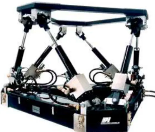
There are a number of devices that are used in industry to calibrate IMUs, and a couple of them were considered for comparison testing purposes. The first device was a three degree of freedom (d.o.f) gyro table, as seen in Figure 1. The platform with all of the IMUs would be mounted to the center gyro, and would spin the IMUs in pitch, roll and yaw. Another option was to use a Stewart Platform, as seen in Figure 2. This device uses six hydraulic, pneumatic or electric actuators to move the top platform with 6 d.o.f; three linear translations in x, y and z, and rotations in pitch, roll and yaw.
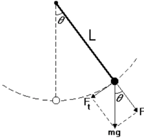
Both of these devices have adequate performance in terms of achieving the desired motion, however they are expensive and fairly complex units. To reduce cost and complexity, the concept selected for the testing apparatus was a simple pendulum with two d.o.f. This design required mounting the platform containing all of the IMUs to the end of a pendulum arm.
Figure 3: Simple pendulum
2.2
Apparatus Specifications
After the concept for a testing apparatus was selected, a list of specifications was produced. A detailed design that met these requirements was critical for a successful set of comparison tests. The apparatus was required to:
• be a free standing structure.
• have a pendulum arm 4 m in length, such that it had a period of approximately four seconds.
• have two independent, orthogonal axis about which the arm can swing.
• be able to complete at least ten cycles, or swings, before the motion decayed signifi-cantly.
• have two angular displacement encoders, one for each axis, to measure the position of the arm.
• have a “platform” at the end of the arm, to which six or seven inertial measurement units, a power source, data acquisition system, and any other required electronics would be mounted.
• have a three or four legged collapsable frame with “feet” for stability.
• be secured with sandbags or anchor bolts if required.
• utilize off-the-shelf components wherever possible.
• utilize in-stock materials wherever possible during construction.
One of the specifications above required the natural frequency of the pendulum to be 0.25 Hz [3]. The reason for this is that Marport Deep Sea Technologies Inc. is involved in the IMU comparison testing, and they wanted the natural frequency of the pendulum to correspond with the natural frequency of their AUV, the SQX-500, in pitch and roll. This ensured that the motion, and performance, of the IMUs during testing would be similar to what they would encounter during the regular operation of the AUV.
2.3
Mechanical Design
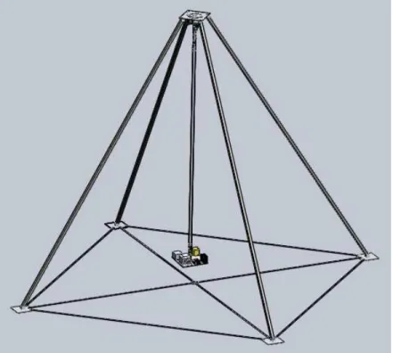
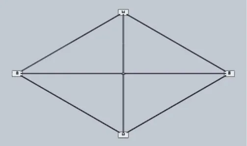
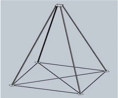
The specifications listed above guided both mechanical design of the apparatus and the design of the platform that contains all of the electronics. A model of the apparatus was created using SolidWorks CAD design software, as seen in Figure 4. This allowed not only an accurate visualization of the apparatus, but additional features available in SolidWorks, such as physical dynamics and interference detection, were valuable tools when refining the design.
The apparatus can be broken down into three main sections; the free-standing frame structure, the pendulum arm capable of swinging with two d.o.f, and the platform containing the elec-tronics. Although the design of each section is not completely independent from the others, this modular design approach was still taken. The three modules were combined to complete the final assembly.
Figure 4: SolidWorks 3D model of the pendulum apparatus
2.3.1 Free-Standing Frame
The design of the frame structure was based on a simple tripod design. However, for extra stability when the pendulum arm was swinging, four “legs” were used instead of three. Also for stability, a “support pad” was also fastened to the end of each leg. To position the legs in a repeatable way every time the apparatus was assembled, four pieces of aluminum bar stock were fastened between the pads, forming a square floor-frame, seen in Figure 5. To keep this square frame from twisting, additional bar stock was added in a “X” configuration.
Figure 5: Floor frame made from aluminum flat bar
At the top of the frame, the four legs were fastened to a horizontal mounting plate. Mounting tabs made from pieces of aluminum channel were used to pin the legs to the support pads and top mounting plate.
The dimensions and geometry of the frame were restricted by the required length of the pen-dulum arm, and the fact that the arm must swing 30 degrees from the vertical without any interference. Therefore, each leg was angled away from the top plate at 35 degrees from the vertical for clearance. Also, the height of the frame was dimensioned to be 4.5 m, thus making the square footprint of the apparatus approximately 5 m by 5 m.
The entire frame structure was made from aluminum for its lightweight and good machining characteristics. The four support legs were made from 50.8 mm aluminum square tubing with 3.2 mm wall thickness. The support pads and top mounting plate were made from 6.35 mm aluminum plate, and the floor frame was made from 38.1 mm by 6.35 mm aluminum flat bar. As mentioned previously, the mounting tabs were made from sections of 76.2 mm x 50.8 mm channel with 9.5 mm wall thickness [4].
Figure 6: Assembled frame structure
2.3.2 Pendulum Arm Assembly
The design of the pendulum arm itself was quite simple, as it was only a 4 m long piece of 38.1 mm aluminum tubing with 5.08 mm wall thickness. Most of the design work for the arm assembly went into making the arm capable of swinging about two axes, and being able to measure the position of the arm at any given time.
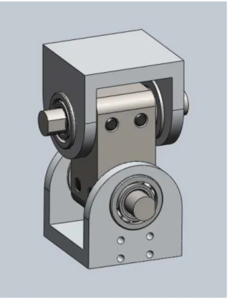
To get the required two degrees of freedom of the pendulum arm, the design of the arm pivot was based on a simple universal joint, also known as a Cardan joint. These two d.o.f joints are based on the design of gimbals and are commonly used for power transmission between two shafts. With slight modifications to the standard design, a universal joint was the best option to achieve the required motion in the pendulum arm yet would allow the rotation about each axis to be separately measured.
As seen in Figures 7, 8 and 9, the design of the pivot for the pendulum consisted of two “yokes” that were positioned orthogonal to each other. A 12.7 mm shaft ran through each yoke and through a “gimbal block,” which connected the two yokes together. The rotation of the
shafts was coupled to the rotation of the gimbal block due to the dowel pins that were inserted through both parts. Each shaft was supported by two ball bearings, which were housed in the yokes, to reduce friction thus making the motion of the arm decay more slowly over time.
Figure 7: Universal joint design
The rotation of the shafts, and therefore the position of the arm, was measured with two Trans-Tek angle encoders with “infinite” resolution (depending on the analog to digital converters) . One of the encoders was fastened to the top mounting plate, and the encoder shaft was coupled to the shaft that ran though the top yoke. The second encoder was mounted to the pendulum arm itself, and the shaft of this encoder was coupled to the shaft that ran though the bottom yoke. By combining the outputs from the two encoders, and knowing the geometry of the arm assembly, the position, orientation and expected accelerations of any point along the arm or platform can be calculated.
As seen in Figure 9, the top yoke was welded to a piece of pipe, and the pipe was welded to another plate. This assembly gets bolted to the top mounting plate, seen in Figure 8. The bottom yoke was also welded to a piece of pipe, along with a bracket to mount the lower encoder. To ease assembly and disassembly of the apparatus, the 4 m arm was designed to be
Figure 8: Angle encoders attached to universal joint
removable. To attach the arm to the universal joint, the pendulum arm pipe was placed over, and pinned to, a “spigot” that was also inserted and pinned to the piece of pipe on the universal joint.
Figure 9: Universal joint assembly
2.3.3 Electronics Platform
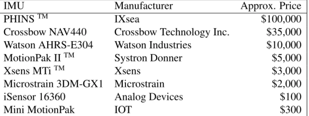
The design of the platform that contained all of the IMUs units was constrained by two things; the platform had to be large enough so all of the IMUs could be mounted, and once the
platform was assembled it had to be balanced so that the motion of the pendulum remained as natural as possible. A list of the IMUs that were selected for performance comparison testing can be seen in Table 1 below.
IMU Manufacturer Approx. Price
PHINSTM IXsea $100,000
Crossbow NAV440 Crossbow Technology Inc. $35,000
Watson AHRS-E304 Watson Industries $10,000
MotionPak IITM Systron Donner $5,000
Xsens MTiTM Xsens $3,000
Microstrain 3DM-GX1 Microstrain $2,000
iSensor 16360 Analog Devices $100
Mini MotionPak IOT $300
Table 1: Selected IMUs for comparison testing
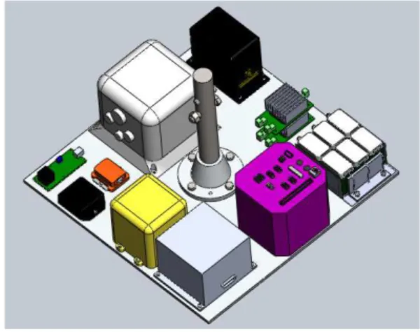
Along with these nine units, a Data Acquisition System (DAS), six Lithium-ion batteries, two DC/DC converters, and some terminal blocks were required to be mounted to the platform. A 3D model of each IMU, along with the other electrical components, was produced so the platform could be laid out in the most efficient way possible. All of the electronics were weighed, and their mass properties were inserted into their respective SolidWorks models. The position of each model on the platform was decided by trial and error; a potential arrangement was decided upon, then the center of mass of the platform was calculated. If the center of mass was not close enough to the center of the plate, within tolerance, then the process was repeated.
Figure 10: Platform with flange Figure 11: Platform with electronics
The platform itself was simply a square piece of 6.35 mm aluminum plate. A number of holes were drilled and tapped to secure the electronic components with threaded fasteners. The final dimensions of the platform to accommodate the electronics was 508 mm square. In order to fasten the platform to the bottom of the pendulum arm, a flange assembly was added, seen in Figure 10. This flange gets bolted to the platform with four fasteners, and pinned to the arm with a 12.7 mm dowel pin.
2.3.4 Final Assembly
After the initials designs for each of the three sections were complete, the individual assem-blies were integrated into one final assembly. Any small issues with the design were quickly noticed and fixed. Once the assembly was problem free, engineering drawings were produced for each component for the fabrication process.
2.4
Fabrication
The fabrication of the pendulum apparatus was completed in IOT’s machine shop. As pre-viously mentioned, the design of the apparatus was kept as simple as possible to reduce fab-rication time. Along with this, the majority of the components were machined from 6061
aluminum, which has very good machining characteristics, and thus reduced fabrication time. Fabrication of the apparatus required the use of a manual milling machine and lathe. There was no computer numerical controlled machining required, which saved time and money. Examples of machining set-ups and procedures can be seen in the following images.
Figure 12: Machining the universal shafts
Figure 15: Universal assembly Figure 16: Machining the flange
3
Set-up Procedures and Calibration
3.1
Assembling the Apparatus
After fabrication was complete, the apparatus was assembled at the far end of the Clear Water Towing Tank in IOT. Due to the size of the pendulum apparatus, certain procedures had to be followed during set-up, and are summarized in the following list:
1. The floor frame, made from the aluminum flat bar and the support pads, was laid out and bolted together.
2. The mounting tabs were pinned and bolted to the four support pads. 3. The universal joint assembly and the pendulum arm were pinned together.
4. The four support legs, along the pendulum arm assembly, were laid horizontally on the floor.
5. Four mounting tabs were fastened to the top mounting plate, along with the four support legs and pendulum arm assembly.
6. The top mounting plate, support legs and arm assembly were then hoisted vertically using an overhead crane, and positioned in the center of the floor frame.
7. Each support leg was moved to its support pad at the corner of the frame and bolted to the mounting tabs.
8. The two angle encoders were installed onto the universal joint, and their cables were wrapped down the pendulum arm.
9. All the electronics were fastened to the platform, the flange assembly was installed, and then the platform was pinned to the bottom of the arm.
Figures 17 through 20 show the assembled appartus.
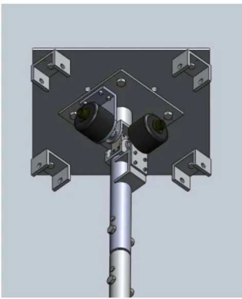
Figure 19: Installed electronics platform Figure 20: Top mounting plate
3.2
Calibration
Once the apparatus is assembled, certain calibrations have to be performed. For example, the angle encoders have a linear range in their output from -30 to +30 degrees. The design of the mounting brackets for the encoders required that a reference “notch” on the end of the encoder shafts be pointed straight down, inline with the axis of the pendulum arm. Therefore, if the shafts are not positioned correctly when they are coupled to the universal shafts, the output from the encoders will not give the true position of the pendulum arm, and a calibration is required.
Along with this, each of the IMUs has its own origin and coordinate system. For example, some of the units might follow the “left-hand rule” while others will use the “right-hand rule” when measuring accelerations. Also, the way the units are arranged on the platform, some devices may be measuring “pitch” while others will be measuring “roll” for the exact same motion. This is not an issue, however, because the IMUs use the same components to measure accelerations along each axis, so there will be no bias in that regard.
During data analysis, the different coordinate systems and positions of the devices on the platform will be accounted for. This will be achieved by choosing one origin and coordinate
system on the platform itself, and the origins and coordinate systems of all the devices will be referenced from that by a simple translation and rotation. This will make a direct comparison of the performance of each unit much easier.
Other calibrations that will be required are due to inaccuracies during the machining process. For example, the two shafts going through the “gimbal block” may not be exactly orthogonal to each other. Also, there are multiple pinned connections from the universal joint down to the platform. Therefore, if the encoders output motion only in “pitch,” for example, the IMUs units on the platform may also be experiencing a small amount of “roll” as well due to small misalignments in the pinned connections.
4
Testing Procedures and Data Analysis
4.1
Testing Procedures
There will be two main types of tests performed using the pendulum apparatus. The first type of test is static in nature, and involves holding the pendulum arm at a specified angle for a period of time. The purpose of this test is to compare the performance of the IMUs in terms of integration “drift.” This is the phenomenon where small errors in acceleration measurements get integrated into larger errors in velocity, and even larger errors in position. All IMUs are subject to this type of unwanted behavior which can be detrimental for long duration applications. These tests will determine which IMUs are better suited for long mission times. The second type of testing to be performed using the apparatus is dynamic, and involves allowing the pendulum arm to swing freely. The dynamic tests will include pure pitch and roll tests where the arm is swinging in a single plane, as well as tests with a combination of pitch and roll where the platform is moving in an elliptical path. The results from the dynamic tests will determine which units are better suited to applications where there are higher acceleration
rates, and where short term accuracy is critical.
As mentioned previously, the pendulum apparatus only has two degrees of freedom, which means it can test the units in terms of pitch and roll, but not it yaw. To get around this, the platform containing the IMUs will be removed from the bottom of the pendulum arm, and placed on a rotary table available at IOT. This rotary table will be able to complete any yaw tests that are required. Combining the results from the static, dynamic and rotary table tests will give a thorough performance comparison of the available IMUs.
4.2
Sources of Error
One possible source of error in the results could come from improper calibrations during set-up. An error such as this would show up as a constant offset throughout the entire data set. Another source of error that would be harder to notice is that the pendulum arm may deflect over its 4 m length. This would result in the measured angle from the INS units to be different from that measured from the encoders at the top of the arm.
The platform containing the INS units could also deflect a small amount under load. Conse-quently, certain regions on the platform might deflect to different angles, causing discrepancies in the outputs from the devices. Seeing as how the platform is well balanced, this effect should be kept to a minimum.
Another possible source of error, or unwanted “noise” in the data, was observed during as-sembly. If the pendulum arm was subjected to a “hit” or impact, this induced a high frequency vibration along its length and in the platform, and these accelerations would be picked up by the IMUs. This would appear in the results as a high frequency signal from the vibrations overlaid on the low frequency signal from the motion of the pendulum. If this is the case for some of the tests, a simple filter could be applied to remove the unwanted “noise.”
4.3
Preliminary Results
Initial testing was performed on five of the IMUs. The data were recorded using the PC-104 DAS that was located on the platform along with the other electronics. The two angle encoders were not used for the first test because an analog to digital converter was not available. The five units that were tested for the initial run were the PHINS, Watson, Xsens, Microstrain and MotionPak II devices. Three dynamic tests were performed; one test attempted pure “roll” in the pendulum arm, one test was pure “pitch,” and the final test was a combination of the two whereby the platform travelled along a “circular” or “elliptical” path.
Figure 21 shows the output from the PHINS in pitch and roll. The green line is roll, and red is the pitch, the horizontal axis shows the time in seconds and the vertical axis shows the measured angle from the unit in degrees. As seen on the image, this test was not purely in roll as intended. The pendulum arm was not pulled back exactly on the roll plane when it was released. Therefore, as the arm began to swing back and forth, it also began to “walk” around the frame in a similar fashion to precession in a Focault pendulum. As the roll began to decay, the pitch was increasing in amplitude indicating precession in the motion.
The second test was intended to be purely in pitch, and the result was much more successful than the previous attempt. Once again, Figure 22 shows the output from the PHINS unit in pitch and roll. One observation that can be noted from this graph is the exponential decay in the motion of the pendulum arm. By fitting a curve to these data, damping coefficients can be determined that include air resistance and friction within the bearings. Also, seen in Figure 23, which is a close up view of two of the peak amplitudes, the period of this swing if very close to 4 seconds, indicating a frequency of approximately 0.25 Hz.
The final dynamic test that was performed was a combination of pitch and roll, i.e the platform was swinging around in a circular fashion. Figure 24 shows the output from the PHINS. This
Figure 21: PHINS output in pitch and roll during the first test
Figure 22: PHINS output in pitch and roll during the second test
graph demonstrates that the platform was swinging with an elliptical path, and along with this, the fact that the larger amplitudes are changing from pitch to roll indicate that there was
Figure 23: Peak to peak period is approximately four seconds precession occurring in this test as well.
The real purpose for testing is to be able to make direct comparisons, and an example of this is seen in Figure 25. This graph compares the output from the PHINS and Watson units in pitch during the second dynamic test that was performed. Their outputs are very similar, however the PHINS measured a larger peak than the Watson. If the angle encoders were available for this test, these results could be compared to the output from the encoders. This would determine which unit was more accurate.
Figure 25: PHINS vs. Watson in pitch during the second test
The previous type of graph is the desired result once complete testing and data analysis are finished. Graphs for pitch, roll, yaw and accelerations will be produced that compare all of the INS. These preliminary tests can not be used for comparison purposes as no calibrations were performed on the apparatus.
5
Conclusions
A direct and simultaneous comparison of several IMUs has never been conducted previously, giving motivation for this type of test at IOT. Comparing the performance of the IMUs avail-able at IOT will provide a reliavail-able reference for researchers when choosing an IMU for a specific application in the future. The following list summarizes the design process and vali-dation of the testing apparatus.
1. A free-standing pendulum was selected as the testing apparatus for its simplicity and low cost.
2. Specifications for the apparatus were defined, for example, the arm must be 4 m in length, be able to swing with two degrees of freedom, and an electronics platform with all of the IMUs would mount to the bottom of the arm.
3. A 3D model of the apparatus was created using SolidWorks software and engineering drawings were produced once the design was finalized.
4. The apparatus was fabricated in IOT’s machine shop and assembled on the premises . 5. Preliminary tests verified that the apparatus was fully functional and suitable for
com-paring the performance of each IMU.
The initial tests that were performed using the apparatus are a “proof of concept,” however, no conclusions regarding the performance of each unit can be drawn from the present results. Additional tests will be performed in January 2011 and the assessment will then be completed.
6
Recommendations
The following work should be performed in the future to get reliable and useful results from the performance comparison tests:
• All of the IMUs and the angle encoders should be set up for the actual testing.
• The apparatus should be calibrated as discussed previously.
• During data analysis, determine if any sources of error from the apparatus are invalidat-ing the results, and address them as necessary.
• Perform “yaw” tests on the entire IMU platform on the rotary table available at NRC-IOT.
7
References
[1] A. D. King,“Inertial Navigation - Forty Years of Evolution”. Gec Review, Vol. 13, pp, July 1998, 140-149
[2] S. G. Smith, “Modern Inertial Technology”. Journal of Navigation, Vol. 46, 1993, p 449
[3] Weisstein, Eric W. (2007). ”Simple Pendulum”. Eric Weisstein’s world of science. Wol-fram Research.
Appendix A
Detailed Drawings
.625 .505
.250 10-24 UNC THRU2X .150 THRU
.750 .188 .375 .563 NOTES: 1) QUANTITY: 2 2) MATERIAL: ALUMINUM 3) FINISH: N/A 4) WEIGHT: N/A A B C D E A B C D E 8 7 6 5 4 3 2 1 DESCRIPTION
PROJECT TITLE ASSEMBLY REFERENCE
THE INFORMATION CONTAINED IN THIS DOCUMENT IS CONFIDENTIAL AND SHALL NOT BE MADE PUBLIC, OR COPIED, OR USED AS THE BASIS FOR THE MANUFACTURE, OR SALE OF ITEMS UNLESS SPECIFICALLY AUTHORIZED IN WRITING BY MARPORT CANADA INC. THIS DOCUMENT IS THE PROPERTY OF MARPORT CANADA INC. AND IS SUBJECT TO RETURN ON DEMAND. MARPORT CANADA INC.50 HARBOUR DRIVE, ST. JOHN'S, NEWFOUNDLAND, A1C 6J4
CHECKED BY APPROVED BY
THIRD ANGLE PROJECTION DIMENSIONS AND
TOLERANCES PER ASME Y14.5M-1994
DATE DRAWN BY
UNLESS OTHERWISE SPECIFIED DIMENSIONS IN TOLERANCES INCHES MILLIMETERS X.X X.XX X.XXX 0.06 0.02 0.005 X X.X 0.51
ADT SHAFT COUPLING 12/10/2010
TH INCHES
.048 4.606 2.500 R.079 6.961 4.689 2.750 .970 6.211 4X .266 THRU ALL .375 4.961 1.000 1.000 NOTES: 1) QUANTITY: 2) MATERIAL: 3) FINISH: 4) WEIGHT: A B C D E A B C D E 8 7 6 5 4 3 2 1 OF
PART / DRAWING NUMBER REV LETTER SHEET NUMBER DESCRIPTION
PROJECT TITLE ASSEMBLY REFERENCE
THE INFORMATION CONTAINED IN THIS DOCUMENT IS CONFIDENTIAL AND SHALL NOT BE MADE PUBLIC, OR COPIED, OR USED AS THE BASIS FOR THE MANUFACTURE, OR SALE OF ITEMS UNLESS SPECIFICALLY AUTHORIZED IN WRITING BY MARPORT CANADA INC. THIS DOCUMENT IS THE PROPERTY OF MARPORT CANADA INC. AND IS SUBJECT TO RETURN ON DEMAND. MARPORT CANADA INC.50 HARBOUR DRIVE, ST. JOHN'S, NEWFOUNDLAND, A1C 6J4
SCALE CHECKED BY APPROVED BY
SHEET SIZE THIRD ANGLE PROJECTION
DO NOT SCALE DRAWING DIMENSIONS AND
TOLERANCES PER ASME Y14.5M-1994
DATE DRAWN BY
UNLESS OTHERWISE SPECIFIED DIMENSIONS IN TOLERANCES INCHES MILLIMETERS X.X X.XX X.XXX 0.06 0.02 0.005 X X.X X.XX 0.1 0.5 1 A 1 1 1:5 31/12/2010 EA CB DB MILLIMETERS
-SolidWorks Student Edition.
For Academic Use Only.
.188 .188 1.000 .375 3.125 3.500 2X .266 THRU ALL .625 2.000 NOTES: 1) QUANTITY: 2
2) MATERIAL: Aluminum Angle 3) FINISH: N/A 4) WEIGHT: N/A A B C D E A B C D E 8 7 6 5 4 3 2 1
PART / DRAWING NUMBER DESCRIPTION
PROJECT TITLE ASSEMBLY REFERENCE
THE INFORMATION CONTAINED IN THIS DOCUMENT IS CONFIDENTIAL AND SHALL NOT BE MADE PUBLIC, OR COPIED, OR USED AS THE BASIS FOR THE MANUFACTURE, OR SALE OF ITEMS UNLESS SPECIFICALLY AUTHORIZED IN WRITING BY MARPORT CANADA INC. THIS DOCUMENT IS THE PROPERTY OF MARPORT CANADA INC. AND IS SUBJECT TO RETURN ON DEMAND. MARPORT CANADA INC.50 HARBOUR DRIVE, ST. JOHN'S, NEWFOUNDLAND, A1C 6J4
CHECKED BY APPROVED BY
THIRD ANGLE PROJECTION DIMENSIONS AND
TOLERANCES PER ASME Y14.5M-1994
DATE DRAWN BY
UNLESS OTHERWISE SPECIFIED DIMENSIONS IN TOLERANCES INCHES MILLIMETERS X.X X.XX X.XXX 0.06 0.02 0.005 X X.X 0.5 1 Battery Support 01/12/2010 T. HOUSE INCHES
SolidWorks Student Edition.
For Academic Use Only.
2.188 2.000
1.000 2.000 R.950
10-24 UNC THRU ALL4X .150 THRU ALL
.375 1.625 1.250 2.500 .313 .313 3.000 .313 NOTES: 1) QUANTITY: 1
2) MATERIAL: ALUMINUM U - CHANNEL 3) FINISH: N/A 4) WEIGHT: N/A A B C D E A B C D E 8 7 6 5 4 3 2 1 OF
PART / DRAWING NUMBER REV LETTER SHEET NUMBER DESCRIPTION
PROJECT TITLE ASSEMBLY REFERENCE
THE INFORMATION CONTAINED IN THIS DOCUMENT IS CONFIDENTIAL AND SHALL NOT BE MADE PUBLIC, OR COPIED, OR USED AS THE BASIS FOR THE MANUFACTURE, OR SALE OF ITEMS UNLESS SPECIFICALLY AUTHORIZED IN WRITING BY MARPORT CANADA INC. THIS DOCUMENT IS THE PROPERTY OF MARPORT CANADA INC. AND IS SUBJECT TO RETURN ON DEMAND. MARPORT CANADA INC.50 HARBOUR DRIVE, ST. JOHN'S, NEWFOUNDLAND, A1C 6J4
SCALE CHECKED BY APPROVED BY
SHEET SIZE THIRD ANGLE PROJECTION
DO NOT SCALE DRAWING DIMENSIONS AND
TOLERANCES PER ASME Y14.5M-1994
DATE DRAWN BY
UNLESS OTHERWISE SPECIFIED DIMENSIONS IN TOLERANCES INCHES MILLIMETERS X.X X.XX X.XXX 0.06 0.02 0.005 X X.X X.XX 0.1 0.5 1 A
BOTTOM ADT ARM MOUNT
1 1 2:3 25/10/2010 TH INCHES B
.375 1.625 3.007 3.875 4.210 4.408 5.125 .375 1.625 4X .221 THRU 1.000 3X .180 THRU 1.114 .192 1.694 1.000 .188 2.000 NOTES: 1) QUANTITY: 1
2) MATERIAL: 3/16" X 2" ALUMINUM BAR 3) FINISH: N/A 4) WEIGHT: N/A A B C D E A B C D E 8 7 6 5 4 3 2 1 DESCRIPTION
PROJECT TITLE ASSEMBLY REFERENCE
THE INFORMATION CONTAINED IN THIS DOCUMENT IS CONFIDENTIAL AND SHALL NOT BE MADE PUBLIC, OR COPIED, OR USED AS THE BASIS FOR THE MANUFACTURE, OR SALE OF ITEMS UNLESS SPECIFICALLY AUTHORIZED IN WRITING BY MARPORT CANADA INC. THIS DOCUMENT IS THE PROPERTY OF MARPORT CANADA INC. AND IS SUBJECT TO RETURN ON DEMAND. MARPORT CANADA INC.50 HARBOUR DRIVE, ST. JOHN'S, NEWFOUNDLAND, A1C 6J4
CHECKED BY APPROVED BY
THIRD ANGLE PROJECTION DIMENSIONS AND
TOLERANCES PER ASME Y14.5M-1994
DATE DRAWN BY
UNLESS OTHERWISE SPECIFIED DIMENSIONS IN TOLERANCES INCHES MILLIMETERS X.X X.XX X.XXX 0.06 0.02 0.005 X X.X 0.51
BOTTOM ADT MOUNT 25/10/2010
TH INCHES
2.500 .625 .313 .938 .500 2.000 2X .500 THRU ALL 4X .250 THRU ALL 1.250 1.250 4X R.250 NOTES: 1) QUANTITY: 1 2) MATERIAL: ALUMINUM 3) FINISH: N/A 4) WEIGHT: N/A A B C D E A B C D E 8 7 6 5 4 3 2 1 OF
PART / DRAWING NUMBER REV LETTER SHEET NUMBER DESCRIPTION
PROJECT TITLE ASSEMBLY REFERENCE
THE INFORMATION CONTAINED IN THIS DOCUMENT IS CONFIDENTIAL AND SHALL NOT BE MADE PUBLIC, OR COPIED, OR USED AS THE BASIS FOR THE MANUFACTURE, OR SALE OF ITEMS UNLESS SPECIFICALLY AUTHORIZED IN WRITING BY MARPORT CANADA INC. THIS DOCUMENT IS THE PROPERTY OF MARPORT CANADA INC. AND IS SUBJECT TO RETURN ON DEMAND. MARPORT CANADA INC.50 HARBOUR DRIVE, ST. JOHN'S, NEWFOUNDLAND, A1C 6J4
SCALE CHECKED BY APPROVED BY
SHEET SIZE THIRD ANGLE PROJECTION
DO NOT SCALE DRAWING DIMENSIONS AND
TOLERANCES PER ASME Y14.5M-1994
DATE DRAWN BY
UNLESS OTHERWISE SPECIFIED DIMENSIONS IN TOLERANCES INCHES MILLIMETERS X.X X.XX X.XXX 0.06 0.02 0.005 X X.X X.XX 0.1 0.5 1 A CENTER BLOCK 1 1 1:1 08/10/2010 TH INCHES A
4.0
.25 4.0 3/8-24 UNF THRU4X .332 THRU
4X .250 THRU .884 1.414 .884 1.414 NOTES: 1) QUANTITY: 1
2) MATERIAL: ALUMINUM PLATE 3) FINISH: N/A 4) WEIGHT: N/A A B C D E A B C D E 8 7 6 5 4 3 2 1 DESCRIPTION
PROJECT TITLE ASSEMBLY REFERENCE
THE INFORMATION CONTAINED IN THIS DOCUMENT IS CONFIDENTIAL AND SHALL NOT BE MADE PUBLIC, OR COPIED, OR USED AS THE BASIS FOR THE MANUFACTURE, OR SALE OF ITEMS UNLESS SPECIFICALLY AUTHORIZED IN WRITING BY MARPORT CANADA INC. THIS DOCUMENT IS THE PROPERTY OF MARPORT CANADA INC. AND IS SUBJECT TO RETURN ON DEMAND. MARPORT CANADA INC.50 HARBOUR DRIVE, ST. JOHN'S, NEWFOUNDLAND, A1C 6J4
CHECKED BY APPROVED BY
THIRD ANGLE PROJECTION DIMENSIONS AND
TOLERANCES PER ASME Y14.5M-1994
DATE DRAWN BY
UNLESS OTHERWISE SPECIFIED DIMENSIONS IN TOLERANCES INCHES MILLIMETERS X.X X.XX X.XXX 0.06 0.02 0.005 X X.X 0.51 CENTER PAD 08/10/2010 TH INCHES
.375 2.375 12.000 2 A A NOTES: 1) QUANTITY: 1 2) MATERIAL: ALUMINUM 3) FINISH: N/A 4) WEIGHT: N/A A B C D E A B C D E 8 7 6 5 4 3 2 1 OF
PART / DRAWING NUMBER REV LETTER SHEET NUMBER DESCRIPTION
PROJECT TITLE ASSEMBLY REFERENCE
THE INFORMATION CONTAINED IN THIS DOCUMENT IS CONFIDENTIAL AND SHALL NOT BE MADE PUBLIC, OR COPIED, OR USED AS THE BASIS FOR THE MANUFACTURE, OR SALE OF ITEMS UNLESS SPECIFICALLY AUTHORIZED IN WRITING BY MARPORT CANADA INC. THIS DOCUMENT IS THE PROPERTY OF MARPORT CANADA INC. AND IS SUBJECT TO RETURN ON DEMAND. MARPORT CANADA INC.50 HARBOUR DRIVE, ST. JOHN'S, NEWFOUNDLAND, A1C 6J4
SCALE CHECKED BY APPROVED BY
SHEET SIZE THIRD ANGLE PROJECTION
DO NOT SCALE DRAWING DIMENSIONS AND
TOLERANCES PER ASME Y14.5M-1994
DATE DRAWN BY
UNLESS OTHERWISE SPECIFIED DIMENSIONS IN TOLERANCES INCHES MILLIMETERS X.X X.XX X.XXX 0.06 0.02 0.005 X X.X X.XX 0.1 0.5 1 A FLANGE ASSEMBLY 1 1 1:5 17/11/2010 TH INCHES A
.375 5.00 4X .377 THRU ALL 2X .250 -.000+.001 THRU ALL 1.500 THRU ALL 1.414 2.000 1.414 2.000 1.414 1.414 NOTES: 1) QUANTITY: 1 2) MATERIAL: ALUMINUM 3) FINISH: N/A 4) WEIGHT: N/A
NOTE: RC1 SLIDING FIT WITH "PLATFORM MOUNT" A B C D E A B C D E 8 7 6 5 4 3 2 1 DESCRIPTION
PROJECT TITLE ASSEMBLY REFERENCE
THE INFORMATION CONTAINED IN THIS DOCUMENT IS CONFIDENTIAL AND SHALL NOT BE MADE PUBLIC, OR COPIED, OR USED AS THE BASIS FOR THE MANUFACTURE, OR SALE OF ITEMS UNLESS SPECIFICALLY AUTHORIZED IN WRITING BY MARPORT CANADA INC. THIS DOCUMENT IS THE PROPERTY OF MARPORT CANADA INC. AND IS SUBJECT TO RETURN ON DEMAND. MARPORT CANADA INC.50 HARBOUR DRIVE, ST. JOHN'S, NEWFOUNDLAND, A1C 6J4
CHECKED BY APPROVED BY
THIRD ANGLE PROJECTION DIMENSIONS AND
TOLERANCES PER ASME Y14.5M-1994
DATE DRAWN BY
UNLESS OTHERWISE SPECIFIED DIMENSIONS IN TOLERANCES INCHES MILLIMETERS X.X X.XX X.XXX 0.06 0.02 0.005 X X.X 0.51 FLANGE BASE 17/10/2010 TH INCHES
2.000 14.04° 1.500 2.000 3.000 NOTES: 1) QUANTITY: 1 2) MATERIAL: ALUMINUM 3) FINISH: N/A 4) WEIGHT: N/A THRU ALL
NOTE: RC1 SLIDING FIT WITH "PLATFORM MOUNT" A B C D E A B C D E 8 7 6 5 4 3 2 1 OF
PART / DRAWING NUMBER REV LETTER SHEET NUMBER DESCRIPTION
PROJECT TITLE ASSEMBLY REFERENCE
THE INFORMATION CONTAINED IN THIS DOCUMENT IS CONFIDENTIAL AND SHALL NOT BE MADE PUBLIC, OR COPIED, OR USED AS THE BASIS FOR THE MANUFACTURE, OR SALE OF ITEMS UNLESS SPECIFICALLY AUTHORIZED IN WRITING BY MARPORT CANADA INC. THIS DOCUMENT IS THE PROPERTY OF MARPORT CANADA INC. AND IS SUBJECT TO RETURN ON DEMAND. MARPORT CANADA INC.50 HARBOUR DRIVE, ST. JOHN'S, NEWFOUNDLAND, A1C 6J4
SCALE CHECKED BY APPROVED BY
SHEET SIZE THIRD ANGLE PROJECTION
DO NOT SCALE DRAWING DIMENSIONS AND
TOLERANCES PER ASME Y14.5M-1994
DATE DRAWN BY
UNLESS OTHERWISE SPECIFIED DIMENSIONS IN TOLERANCES INCHES MILLIMETERS X.X X.XX X.XXX 0.06 0.02 0.005 X X.X X.XX 0.1 0.5 1 A FLANGE 1 1 1:2 17/11/2010 TH INCHES A
.250 20.000 20.000 10.000 10.000 A1 A2 B1 B2 C1 C2 B3 B4 C3 C4 A3 A4 C5 C6 D1 E1 C7 C8 D2 D3 E2 D4 F1 F2 G1 G2 H1 G3 G4 H2 G5 G6 F3 F4 X Y NOTES: 1) QUANTITY: 1
2) MATERIAL: 1/4" ALUMINUM PLATE 3) FINISH: N/A
4) WEIGHT: N/A
TAG X LOC Y LOC SIZE
A1 -9.500 -8.899 1/4-20 UNC THRU ALL
A2 -9.500 -6.149 1/4-20 UNC THRU ALL
A3 -3.289 -8.899 1/4-20 UNC THRU ALL
A4 -3.289 -6.149 1/4-20 UNC THRU ALL
B1 -9.004 -3.430 .154 THRU ALL
B2 -9.004 1.953 .154 THRU ALL
B3 -5.246 -3.430 .154 THRU ALL
B4 -5.246 1.953 .154 THRU ALL
C1 -8.569 4.000 10-32 UNF THRU ALL
C2 -8.569 9.500 10-32 UNF THRU ALL
C3 -4.069 4.000 10-32 UNF THRU ALL
C4 -4.069 9.500 10-32 UNF THRU ALL
C5 -2.082 5.050 10-32 UNF THRU ALL
C6 -2.082 9.670 10-32 UNF THRU ALL
C7 -.102 5.050 10-32 UNF THRU ALL
C8 -.102 9.670 10-32 UNF THRU ALL
D1 -2.000 .000 .377 THRU ALL D2 .000 -2.000 .377 THRU ALL D3 .000 2.000 .377 THRU ALL D4 2.000 .000 .377 THRU ALL E1 -1.41 1.41 .250 -.000+.001 THRU ALL E2 1.41 -1.41 .250 -.000+.001 THRU ALL
F1 3.261 -3.307 1/4-28 UNF THRU ALL
F2 3.261 2.835 1/4-28 UNF THRU ALL
F3 9.403 -3.307 1/4-28 UNF THRU ALL
F4 9.403 2.835 1/4-28 UNF THRU ALL
G1 3.698 -9.138 6-32 UNC THRU ALL
G2 3.698 -6.638 6-32 UNC THRU ALL
G3 5.413 4.325 6-32 UNC THRU ALL
G4 5.413 6.313 6-32 UNC THRU ALL
G5 8.948 -9.138 6-32 UNC THRU ALL
G6 8.948 -6.638 6-32 UNC THRU ALL
H1 3.750 8.500 8-32 UNC THRU ALL
H2 6.750 8.500 8-32 UNC THRU ALL
A B C D E A B C D E 8 7 6 5 4 3 2 1 DESCRIPTION
PROJECT TITLE ASSEMBLY REFERENCE
THE INFORMATION CONTAINED IN THIS DOCUMENT IS CONFIDENTIAL AND SHALL NOT BE MADE PUBLIC, OR COPIED, OR USED AS THE BASIS FOR THE MANUFACTURE, OR SALE OF ITEMS UNLESS SPECIFICALLY AUTHORIZED IN WRITING BY MARPORT CANADA INC. THIS DOCUMENT IS THE PROPERTY OF MARPORT CANADA INC. AND IS SUBJECT TO RETURN ON DEMAND. MARPORT CANADA INC.50 HARBOUR DRIVE, ST. JOHN'S, NEWFOUNDLAND, A1C 6J4
CHECKED BY APPROVED BY
THIRD ANGLE PROJECTION DIMENSIONS AND
TOLERANCES PER ASME Y14.5M-1994
DATE DRAWN BY
UNLESS OTHERWISE SPECIFIED DIMENSIONS IN TOLERANCES INCHES MILLIMETERS X.X X.XX X.XXX 0.06 0.02 0.005 X X.X 0.51 IMU PLATFORM 18/11/2010 TH INCHES
1.500 .313 .313 .313 2.000 .531 THRU ALL .391 THRU 2.000 1.000 3.00 1.50 .250 THRU 1.750 NOTES: 1) QUANTITY: 8
2) MATERIAL: Aluminum U - Channel 3) FINISH: N/A 4) WEIGHT: N/A A B C D E A B C D E 8 7 6 5 4 3 2 1 OF
PART / DRAWING NUMBER REV LETTER SHEET NUMBER DESCRIPTION
PROJECT TITLE ASSEMBLY REFERENCE
THE INFORMATION CONTAINED IN THIS DOCUMENT IS CONFIDENTIAL AND SHALL NOT BE MADE PUBLIC, OR COPIED, OR USED AS THE BASIS FOR THE MANUFACTURE, OR SALE OF ITEMS UNLESS SPECIFICALLY AUTHORIZED IN WRITING BY MARPORT CANADA INC. THIS DOCUMENT IS THE PROPERTY OF MARPORT CANADA INC. AND IS SUBJECT TO RETURN ON DEMAND. MARPORT CANADA INC.50 HARBOUR DRIVE, ST. JOHN'S, NEWFOUNDLAND, A1C 6J4
SCALE CHECKED BY APPROVED BY
SHEET SIZE THIRD ANGLE PROJECTION
DO NOT SCALE DRAWING DIMENSIONS AND
TOLERANCES PER ASME Y14.5M-1994
DATE DRAWN BY
UNLESS OTHERWISE SPECIFIED DIMENSIONS IN TOLERANCES INCHES MILLIMETERS X.X X.XX X.XXX 0.06 0.02 0.005 X X.X X.XX 0.1 0.5 1 A MOUNTING TABS 1 1 1:1 10/04/2010 TH INCHES
-.500 A 1 A A 3 5 2 4 DETAIL A SCALE 1 : 1.5
NOTE: PRESS FIT BEARINGS SO FLANGE IS ON INSIDE FACE NOTES: 1) QUANTITY:1 2) MATERIAL: N/A 3) FINISH: N/A 4) WEIGHT: N/A 1 A
ITEM NO. PART NUMBER QTY.
2 Yoke 1
3 Bearings 6383K234 2
4 Bottom ADT arm mount 1
5 Top Pendulum Arm 1
A B C D E A B C D E 8 7 6 5 4 3 2 1 DESCRIPTION
PROJECT TITLE ASSEMBLY REFERENCE
THE INFORMATION CONTAINED IN THIS DOCUMENT IS CONFIDENTIAL AND SHALL NOT BE MADE PUBLIC, OR COPIED, OR USED AS THE BASIS FOR THE MANUFACTURE, OR SALE OF ITEMS UNLESS SPECIFICALLY AUTHORIZED IN WRITING BY MARPORT CANADA INC. THIS DOCUMENT IS THE PROPERTY OF MARPORT CANADA INC. AND IS SUBJECT TO RETURN ON DEMAND. MARPORT CANADA INC.50 HARBOUR DRIVE, ST. JOHN'S, NEWFOUNDLAND, A1C 6J4
CHECKED BY APPROVED BY
THIRD ANGLE PROJECTION DIMENSIONS AND
TOLERANCES PER ASME Y14.5M-1994
DATE DRAWN BY
UNLESS OTHERWISE SPECIFIED DIMENSIONS IN TOLERANCES INCHES MILLIMETERS X.X X.XX X.XXX 0.06 0.02 0.005 X X.X 0.51
PENDULUM ARM ASSEMBLY 12/10/2010
TH INCHES
150.0 2.25 1.500 3X .500 THRU ALL 3X .531 THRU ALL 2.25 1.500 B .200 1.500 SECTION A-A SCALE 1 : 4 .500 .531 .531 .500 DETAIL B SCALE 1 : 2
NOTE: HOLES ARE 90 DEGREES APART
NOTES:
1) QUANTITY: 1
2) MATERIAL: ALUMINUM PIPE - SCHEDULE 80 3) FINISH: N/A
4) WEIGHT: N/A
NOTE: MACHINE 6" OF ID FOR SLIDING FIT WITH "SPIGOT"
NOTE: MACHINE 6" OF ID FOR SLIDING FIT WITH "PLATFORM MOUNT"
A B C D E A B C D E 8 7 6 5 4 3 2 1 OF
PART / DRAWING NUMBER REV LETTER SHEET NUMBER DESCRIPTION
PROJECT TITLE ASSEMBLY REFERENCE
THE INFORMATION CONTAINED IN THIS DOCUMENT IS CONFIDENTIAL AND SHALL NOT BE MADE PUBLIC, OR COPIED, OR USED AS THE BASIS FOR THE MANUFACTURE, OR SALE OF ITEMS UNLESS SPECIFICALLY AUTHORIZED IN WRITING BY MARPORT CANADA INC. THIS DOCUMENT IS THE PROPERTY OF MARPORT CANADA INC. AND IS SUBJECT TO RETURN ON DEMAND. MARPORT CANADA INC.50 HARBOUR DRIVE, ST. JOHN'S, NEWFOUNDLAND, A1C 6J4
SCALE CHECKED BY APPROVED BY
SHEET SIZE THIRD ANGLE PROJECTION
DO NOT SCALE DRAWING DIMENSIONS AND
TOLERANCES PER ASME Y14.5M-1994
DATE DRAWN BY
UNLESS OTHERWISE SPECIFIED DIMENSIONS IN TOLERANCES INCHES MILLIMETERS X.X X.XX X.XXX 0.06 0.02 0.005 X X.X X.XX 0.1 0.5 1 A PENDULUM ARM 1 1 1:33.3 25/10/2010 TH INCHES B
Two Angle Encoders 4 m Pendulum Arm Platform for multiple INS Universal Joint with 2 D.O.F A B C D E A B C D E 8 7 6 5 4 3 2 1 DESCRIPTION
PROJECT TITLE ASSEMBLY REFERENCE
THE INFORMATION CONTAINED IN THIS DOCUMENT IS CONFIDENTIAL AND SHALL NOT BE MADE PUBLIC, OR COPIED, OR USED AS THE BASIS FOR THE MANUFACTURE, OR SALE OF ITEMS UNLESS SPECIFICALLY AUTHORIZED IN WRITING BY MARPORT CANADA INC. THIS DOCUMENT IS THE PROPERTY OF MARPORT CANADA INC. AND IS SUBJECT TO RETURN ON DEMAND. MARPORT CANADA INC.50 HARBOUR DRIVE, ST. JOHN'S, NEWFOUNDLAND, A1C 6J4
CHECKED BY APPROVED BY
THIRD ANGLE PROJECTION DIMENSIONS AND
TOLERANCES PER ASME Y14.5M-1994
DATE DRAWN BY
UNLESS OTHERWISE SPECIFIED DIMENSIONS IN TOLERANCES INCHES MILLIMETERS X.X X.XX X.XXX 0.06 0.02 0.005 X X.X 0.51
INS Testing - Pendulum Apparatus 24/11/2010
.438 .313 .625 1.625 .1875 THRU ALL .125 .500 1.250 .188 .813 .500 4X .206 THRU .500 1.000 NOTES: 1) QUANTITY: 1 2) MATERIAL: ALUMINUM 3) FINISH: N/A 4) WEIGHT: N/A A B C D E A B C D E 8 7 6 5 4 3 2 1 OF
PART / DRAWING NUMBER REV LETTER SHEET NUMBER DESCRIPTION
PROJECT TITLE ASSEMBLY REFERENCE
THE INFORMATION CONTAINED IN THIS DOCUMENT IS CONFIDENTIAL AND SHALL NOT BE MADE PUBLIC, OR COPIED, OR USED AS THE BASIS FOR THE MANUFACTURE, OR SALE OF ITEMS UNLESS SPECIFICALLY AUTHORIZED IN WRITING BY MARPORT CANADA INC. THIS DOCUMENT IS THE PROPERTY OF MARPORT CANADA INC. AND IS SUBJECT TO RETURN ON DEMAND. MARPORT CANADA INC.50 HARBOUR DRIVE, ST. JOHN'S, NEWFOUNDLAND, A1C 6J4
SCALE CHECKED BY APPROVED BY
SHEET SIZE THIRD ANGLE PROJECTION
DO NOT SCALE DRAWING DIMENSIONS AND
TOLERANCES PER ASME Y14.5M-1994
DATE DRAWN BY
UNLESS OTHERWISE SPECIFIED DIMENSIONS IN TOLERANCES INCHES MILLIMETERS X.X X.XX X.XXX 0.06 0.02 0.005 X X.X X.XX 0.1 0.5 1 A PITCH/ROLL LOCK 1 1 1:1 31/12/2010 TH INCHES A
.500 .188 THRU .030 .250 .016 .180 3.125 3.500 3.149 3.188 NOTES: 1) QUANTITY: 1
2) MATERIAL: GROUND STEEL ROD 3) FINISH: N/A 4) WEIGHT: N/A A B C D E A B C D E 8 7 6 5 4 3 2 1 DESCRIPTION
PROJECT TITLE ASSEMBLY REFERENCE
THE INFORMATION CONTAINED IN THIS DOCUMENT IS CONFIDENTIAL AND SHALL NOT BE MADE PUBLIC, OR COPIED, OR USED AS THE BASIS FOR THE MANUFACTURE, OR SALE OF ITEMS UNLESS SPECIFICALLY AUTHORIZED IN WRITING BY MARPORT CANADA INC. THIS DOCUMENT IS THE PROPERTY OF MARPORT CANADA INC. AND IS SUBJECT TO RETURN ON DEMAND. MARPORT CANADA INC.50 HARBOUR DRIVE, ST. JOHN'S, NEWFOUNDLAND, A1C 6J4
CHECKED BY APPROVED BY
THIRD ANGLE PROJECTION DIMENSIONS AND
TOLERANCES PER ASME Y14.5M-1994
DATE DRAWN BY
UNLESS OTHERWISE SPECIFIED DIMENSIONS IN TOLERANCES INCHES MILLIMETERS X.X X.XX X.XXX 0.06 0.02 0.005 X X.X 0.51 PIVOT ROD 2 26/11/2010 T. HOUSE INCHES
3.000 .030 .375 1.188 1.813 2X .250 THRU .5000 NOTES: 1) QUANTITY: 2
2) MATERIAL: GROUND ROD - STEEL 3) FINISH: N/A 4) WEIGHT: N/A A B C D E A B C D E 8 7 6 5 4 3 2 1 OF
PART / DRAWING NUMBER REV LETTER SHEET NUMBER DESCRIPTION
PROJECT TITLE ASSEMBLY REFERENCE
THE INFORMATION CONTAINED IN THIS DOCUMENT IS CONFIDENTIAL AND SHALL NOT BE MADE PUBLIC, OR COPIED, OR USED AS THE BASIS FOR THE MANUFACTURE, OR SALE OF ITEMS UNLESS SPECIFICALLY AUTHORIZED IN WRITING BY MARPORT CANADA INC. THIS DOCUMENT IS THE PROPERTY OF MARPORT CANADA INC. AND IS SUBJECT TO RETURN ON DEMAND. MARPORT CANADA INC.50 HARBOUR DRIVE, ST. JOHN'S, NEWFOUNDLAND, A1C 6J4
SCALE CHECKED BY APPROVED BY
SHEET SIZE THIRD ANGLE PROJECTION
DO NOT SCALE DRAWING DIMENSIONS AND
TOLERANCES PER ASME Y14.5M-1994
DATE DRAWN BY
UNLESS OTHERWISE SPECIFIED DIMENSIONS IN TOLERANCES INCHES MILLIMETERS X.X X.XX X.XXX 0.06 0.02 0.005 X X.X X.XX 0.1 0.5 1 A PIVOT ROD 1 1 1:1 08/10/2010 TH INCHES A
.500 -.000+.001 THRU ALL .531 THRU ALL 2.500 4.000 12.000 1.500 NOTES: 1) QUANTITY: 1 2) MATERIAL: 6061 ALUMINUM 3) FINISH: N/A 4) WEIGHT: N/A
NOTE: RC1 SLIDING FIT WITH "PENDULUM ARM"
A B C D E A B C D E 8 7 6 5 4 3 2 1 DESCRIPTION
PROJECT TITLE ASSEMBLY REFERENCE
THE INFORMATION CONTAINED IN THIS DOCUMENT IS CONFIDENTIAL AND SHALL NOT BE MADE PUBLIC, OR COPIED, OR USED AS THE BASIS FOR THE MANUFACTURE, OR SALE OF ITEMS UNLESS SPECIFICALLY AUTHORIZED IN WRITING BY MARPORT CANADA INC. THIS DOCUMENT IS THE PROPERTY OF MARPORT CANADA INC. AND IS SUBJECT TO RETURN ON DEMAND. MARPORT CANADA INC.50 HARBOUR DRIVE, ST. JOHN'S, NEWFOUNDLAND, A1C 6J4
CHECKED BY APPROVED BY
THIRD ANGLE PROJECTION DIMENSIONS AND
TOLERANCES PER ASME Y14.5M-1994
DATE DRAWN BY
UNLESS OTHERWISE SPECIFIED DIMENSIONS IN TOLERANCES INCHES MILLIMETERS X.X X.XX X.XXX 0.06 0.02 0.005 X X.X 0.51 PLATFORM MOUNT 17/11/2010 TH INCHES
12.00 2X .500 THRU ALL 2X .531 THRU ALL 2.00 1.500 2.00 1.500 1.500-.003+.000 NOTES: 1) QUANTITY:1 2) MATERIAL: ALUMINUM 3) FINISH: N/A 4) WEIGHT: N/A
NOTE: SLIDING FIT WITH "TOP PENDULUM ARM" AND "PENDULUM ARM" A B C D E A B C D E 8 7 6 5 4 3 2 1 OF
PART / DRAWING NUMBER REV LETTER SHEET NUMBER DESCRIPTION
PROJECT TITLE ASSEMBLY REFERENCE
THE INFORMATION CONTAINED IN THIS DOCUMENT IS CONFIDENTIAL AND SHALL NOT BE MADE PUBLIC, OR COPIED, OR USED AS THE BASIS FOR THE MANUFACTURE, OR SALE OF ITEMS UNLESS SPECIFICALLY AUTHORIZED IN WRITING BY MARPORT CANADA INC. THIS DOCUMENT IS THE PROPERTY OF MARPORT CANADA INC. AND IS SUBJECT TO RETURN ON DEMAND. MARPORT CANADA INC.50 HARBOUR DRIVE, ST. JOHN'S, NEWFOUNDLAND, A1C 6J4
SCALE CHECKED BY APPROVED BY
SHEET SIZE THIRD ANGLE PROJECTION
DO NOT SCALE DRAWING DIMENSIONS AND
TOLERANCES PER ASME Y14.5M-1994
DATE DRAWN BY
UNLESS OTHERWISE SPECIFIED DIMENSIONS IN TOLERANCES INCHES MILLIMETERS X.X X.XX X.XXX 0.06 0.02 0.005 X X.X X.XX 0.1 0.5 1 A SPIGOT 1 1 1:5 08/10/2010 TH INCHES A
119.0 2X .250 THRU 2X .391 THRU .50 .250 1.000 .250 1.000 .50 A A 1.00 .25 SECTION A-A SCALE 1 : 2 NOTES: 1) QUANTITY: 4
2) MATERIAL: ALUMINUM BAR 3) FINISH: N/A 4) WEIGHT: N/A A B C D E A B C D E 8 7 6 5 4 3 2 1 DESCRIPTION
PROJECT TITLE ASSEMBLY REFERENCE
THE INFORMATION CONTAINED IN THIS DOCUMENT IS CONFIDENTIAL AND SHALL NOT BE MADE PUBLIC, OR COPIED, OR USED AS THE BASIS FOR THE MANUFACTURE, OR SALE OF ITEMS UNLESS SPECIFICALLY AUTHORIZED IN WRITING BY MARPORT CANADA INC. THIS DOCUMENT IS THE PROPERTY OF MARPORT CANADA INC. AND IS SUBJECT TO RETURN ON DEMAND. MARPORT CANADA INC.50 HARBOUR DRIVE, ST. JOHN'S, NEWFOUNDLAND, A1C 6J4
CHECKED BY APPROVED BY
THIRD ANGLE PROJECTION DIMENSIONS AND
TOLERANCES PER ASME Y14.5M-1994
DATE DRAWN BY
UNLESS OTHERWISE SPECIFIED DIMENSIONS IN TOLERANCES INCHES MILLIMETERS X.X X.XX X.XXX 0.06 0.02 0.005 X X.X 0.51 SUPPORT BRACES 08/10/2010 TH INCHES
2X .250 THRU 2X .391 THRU 164.000 .640 .750 .640 .750 A A .25 1.0 SECTION A-A SCALE 1 : 4 NOTES: 1) QUANTITY:4 2) MATERIAL: ALUMINUM 3) FINISH: N/A 4) WEIGHT: N/A A B C D E A B C D E 8 7 6 5 4 3 2 1 OF
PART / DRAWING NUMBER REV LETTER SHEET NUMBER DESCRIPTION
PROJECT TITLE ASSEMBLY REFERENCE
THE INFORMATION CONTAINED IN THIS DOCUMENT IS CONFIDENTIAL AND SHALL NOT BE MADE PUBLIC, OR COPIED, OR USED AS THE BASIS FOR THE MANUFACTURE, OR SALE OF ITEMS UNLESS SPECIFICALLY AUTHORIZED IN WRITING BY MARPORT CANADA INC. THIS DOCUMENT IS THE PROPERTY OF MARPORT CANADA INC. AND IS SUBJECT TO RETURN ON DEMAND. MARPORT CANADA INC.50 HARBOUR DRIVE, ST. JOHN'S, NEWFOUNDLAND, A1C 6J4
SCALE CHECKED BY APPROVED BY
SHEET SIZE THIRD ANGLE PROJECTION
DO NOT SCALE DRAWING DIMENSIONS AND
TOLERANCES PER ASME Y14.5M-1994
DATE DRAWN BY
UNLESS OTHERWISE SPECIFIED DIMENSIONS IN TOLERANCES INCHES MILLIMETERS X.X X.XX X.XXX 0.06 0.02 0.005 X X.X X.XX 0.1 0.5 1 A SUPPORT BRACE 1 1 1:50 12/10/2010 TH INCHES A
216.5 1.00 .63 1.00 .63 2X .531 THRU ALL D D 2.00 2.00 .13 SECTION D-D SCALE 1 : 4 NOTES: 1) QUANTITY: 4
2) MATERIAL: ALUMNINUM SQUARE TUBE 3) FINISH: N/A 4) WEIGHT: N/A A B C D E A B C D E 8 7 6 5 4 3 2 1 DESCRIPTION
PROJECT TITLE ASSEMBLY REFERENCE
THE INFORMATION CONTAINED IN THIS DOCUMENT IS CONFIDENTIAL AND SHALL NOT BE MADE PUBLIC, OR COPIED, OR USED AS THE BASIS FOR THE MANUFACTURE, OR SALE OF ITEMS UNLESS SPECIFICALLY AUTHORIZED IN WRITING BY MARPORT CANADA INC. THIS DOCUMENT IS THE PROPERTY OF MARPORT CANADA INC. AND IS SUBJECT TO RETURN ON DEMAND. MARPORT CANADA INC.50 HARBOUR DRIVE, ST. JOHN'S, NEWFOUNDLAND, A1C 6J4
CHECKED BY APPROVED BY
THIRD ANGLE PROJECTION DIMENSIONS AND
TOLERANCES PER ASME Y14.5M-1994
DATE DRAWN BY
UNLESS OTHERWISE SPECIFIED DIMENSIONS IN TOLERANCES INCHES MILLIMETERS X.X X.XX X.XXX 0.06 0.02 0.005 X X.X 0.51 SUPPORT LEGS 08/10/2010 TH INCHES
12.00
12.00 3/8-24 UNF THRU4X .332 THRU
4X .250 THRU .750 4.250 4.470 5.000 4.470 5.000 .25 NOTES: 1) QUANTITY: 4 2) MATERIAL: ALUMINUM 3) FINISH: N/A 4) WEIGHT: N/A A B C D E A B C D E 8 7 6 5 4 3 2 1 OF
REV LETTER SHEET NUMBER DESCRIPTION
PROJECT TITLE ASSEMBLY REFERENCE
THE INFORMATION CONTAINED IN THIS DOCUMENT IS CONFIDENTIAL AND SHALL NOT BE MADE PUBLIC, OR COPIED, OR USED AS THE BASIS FOR THE MANUFACTURE, OR SALE OF ITEMS UNLESS SPECIFICALLY AUTHORIZED IN WRITING BY MARPORT CANADA INC. THIS DOCUMENT IS THE PROPERTY OF MARPORT CANADA INC. AND IS SUBJECT TO RETURN ON DEMAND. MARPORT CANADA INC.50 HARBOUR DRIVE, ST. JOHN'S, NEWFOUNDLAND, A1C 6J4
SCALE CHECKED BY APPROVED BY
SHEET SIZE THIRD ANGLE PROJECTION
DO NOT SCALE DRAWING DIMENSIONS AND
TOLERANCES PER ASME Y14.5M-1994
DATE DRAWN BY
UNLESS OTHERWISE SPECIFIED DIMENSIONS IN TOLERANCES INCHES MILLIMETERS X.X X.XX X.XXX 0.06 0.02 0.005 X X.X X.XX 0.1 0.5 1 A 1 1 1:3 10/04/2010 TH INCHES A
PART / DRAWING NUMBER
2.842 3.040 3.375 4.243 .692 1.500 1.614 2.194 4X .266 THRU .531 1.531 .500 2.500 3.000 1.750 .375 .313 NOTES: 1) QUANTITY: 1
2) MATERIAL: 6" ALUMINUM U-CHANNEL 3) FINISH: N/A 4) WEIGHT: N/A A B C D E A B C D E 8 7 6 5 4 3 2 1 DESCRIPTION
PROJECT TITLE ASSEMBLY REFERENCE
THE INFORMATION CONTAINED IN THIS DOCUMENT IS CONFIDENTIAL AND SHALL NOT BE MADE PUBLIC, OR COPIED, OR USED AS THE BASIS FOR THE MANUFACTURE, OR SALE OF ITEMS UNLESS SPECIFICALLY AUTHORIZED IN WRITING BY MARPORT CANADA INC. THIS DOCUMENT IS THE PROPERTY OF MARPORT CANADA INC. AND IS SUBJECT TO RETURN ON DEMAND. MARPORT CANADA INC.50 HARBOUR DRIVE, ST. JOHN'S, NEWFOUNDLAND, A1C 6J4
CHECKED BY APPROVED BY
THIRD ANGLE PROJECTION DIMENSIONS AND
TOLERANCES PER ASME Y14.5M-1994
DATE DRAWN BY
UNLESS OTHERWISE SPECIFIED DIMENSIONS IN TOLERANCES INCHES MILLIMETERS X.X X.XX X.XXX 0.06 0.02 0.005 X X.X 0.51
TOP ADT MOUNT 17/11/2010
TH INCHES
.25 16.00 16.00 4.243 6.364 4.243 6.364 3.000 3.000 8X .531 THRU 4X .391 THRU 4X .250 THRU 6.894 6.894 NOTES: 1) QUANTITY: 1 2) MATERIAL: ALUMINUM 3) FINISH: N/A 4) WEIGHT: N/A A B C D E A B C D E 8 7 6 5 4 3 2 1 OF
PART / DRAWING NUMBER REV LETTER SHEET NUMBER DESCRIPTION
PROJECT TITLE ASSEMBLY REFERENCE
THE INFORMATION CONTAINED IN THIS DOCUMENT IS CONFIDENTIAL AND SHALL NOT BE MADE PUBLIC, OR COPIED, OR USED AS THE BASIS FOR THE MANUFACTURE, OR SALE OF ITEMS UNLESS SPECIFICALLY AUTHORIZED IN WRITING BY MARPORT CANADA INC. THIS DOCUMENT IS THE PROPERTY OF MARPORT CANADA INC. AND IS SUBJECT TO RETURN ON DEMAND. MARPORT CANADA INC.50 HARBOUR DRIVE, ST. JOHN'S, NEWFOUNDLAND, A1C 6J4
SCALE CHECKED BY APPROVED BY
SHEET SIZE THIRD ANGLE PROJECTION
DO NOT SCALE DRAWING DIMENSIONS AND
TOLERANCES PER ASME Y14.5M-1994
DATE DRAWN BY
UNLESS OTHERWISE SPECIFIED DIMENSIONS IN TOLERANCES INCHES MILLIMETERS X.X X.XX X.XXX 0.06 0.02 0.005 X X.X X.XX 0.1 0.5 1 A
TOP MOUNTING PLATE
1 1 1:4 05/10/2010 TH INCHES A
12.00 2.50 .500 THRU ALL .531 THRU ALL 1.500 1.500 .200 NOTES: 1) QUANTITY: 1
2) MATERIAL: ALUMINUM PIPE - SCHEDULE 80 3) FINISH: N/A
NOTE: SLIDING FIT WITH "SPIGOT"
A B C D E A B C D E 8 7 6 5 4 3 2 1 DESCRIPTION
PROJECT TITLE ASSEMBLY REFERENCE
THE INFORMATION CONTAINED IN THIS DOCUMENT IS CONFIDENTIAL AND SHALL NOT BE MADE PUBLIC, OR COPIED, OR USED AS THE BASIS FOR THE MANUFACTURE, OR SALE OF ITEMS UNLESS SPECIFICALLY AUTHORIZED IN WRITING BY MARPORT CANADA INC. THIS DOCUMENT IS THE PROPERTY OF MARPORT CANADA INC. AND IS SUBJECT TO RETURN ON DEMAND. MARPORT CANADA INC.50 HARBOUR DRIVE, ST. JOHN'S, NEWFOUNDLAND, A1C 6J4
CHECKED BY APPROVED BY
THIRD ANGLE PROJECTION DIMENSIONS AND
TOLERANCES PER ASME Y14.5M-1994
DATE DRAWN BY
UNLESS OTHERWISE SPECIFIED DIMENSIONS IN TOLERANCES INCHES MILLIMETERS X.X X.XX X.XXX 0.06 0.02 0.005 X X.X 0.51
TOP PENDULUM ARM 25/10/2010
TH INCHES
1 B B K 2 A A DETAIL K SCALE 2 : 3
NOTE: PRESS FIT BEARINGS SO FLANGE IS ON INSIDE NOTES: 1) QUANTITY: 1 2) MATERIAL: ALUMINUM 3) FINISH: N/A 4) WEIGHT: N/A
ITEM NO. PART NUMBER QTY.
1 UJ Base Mount 1 2 UJ Top Mount 1 3 Yoke 1 4 Bearings 6383K234 2 A B C D E A B C D E 8 7 6 5 4 3 2 1 OF
PART / DRAWING NUMBER REV LETTER SHEET NUMBER DESCRIPTION
PROJECT TITLE ASSEMBLY REFERENCE
THE INFORMATION CONTAINED IN THIS DOCUMENT IS CONFIDENTIAL AND SHALL NOT BE MADE PUBLIC, OR COPIED, OR USED AS THE BASIS FOR THE MANUFACTURE, OR SALE OF ITEMS UNLESS SPECIFICALLY AUTHORIZED IN WRITING BY MARPORT CANADA INC. THIS DOCUMENT IS THE PROPERTY OF MARPORT CANADA INC. AND IS SUBJECT TO RETURN ON DEMAND. MARPORT CANADA INC.50 HARBOUR DRIVE, ST. JOHN'S, NEWFOUNDLAND, A1C 6J4
SCALE CHECKED BY APPROVED BY
SHEET SIZE THIRD ANGLE PROJECTION
DO NOT SCALE DRAWING DIMENSIONS AND
TOLERANCES PER ASME Y14.5M-1994
DATE DRAWN BY
UNLESS OTHERWISE SPECIFIED DIMENSIONS IN TOLERANCES INCHES MILLIMETERS X.X X.XX X.XXX 0.06 0.02 0.005 X X.X X.XX 0.1 0.5 1 A
TOP UNIVERSAL ASSEMBLY
1 1 1:5 10/04/2010 TH INCHES A
.250 4X .531 THRU 2.000 8.00 3.000 3.000 4.00
1/4-20 UNC THRU4X .201 THRU 1.000
2.604 3.604 1.000 4.00 8.00 NOTES: 1) QUANTITY: 1
2) MATERIAL: 1/4" ALUMINUM PLATE 3) FINISH: N/A 4) WEIGHT: N/A A B C D E A B C D E 8 7 6 5 4 3 2 1 DESCRIPTION
PROJECT TITLE ASSEMBLY REFERENCE
THE INFORMATION CONTAINED IN THIS DOCUMENT IS CONFIDENTIAL AND SHALL NOT BE MADE PUBLIC, OR COPIED, OR USED AS THE BASIS FOR THE MANUFACTURE, OR SALE OF ITEMS UNLESS SPECIFICALLY AUTHORIZED IN WRITING BY MARPORT CANADA INC. THIS DOCUMENT IS THE PROPERTY OF MARPORT CANADA INC. AND IS SUBJECT TO RETURN ON DEMAND. MARPORT CANADA INC.50 HARBOUR DRIVE, ST. JOHN'S, NEWFOUNDLAND, A1C 6J4
CHECKED BY APPROVED BY
THIRD ANGLE PROJECTION DIMENSIONS AND
TOLERANCES PER ASME Y14.5M-1994
DATE DRAWN BY
UNLESS OTHERWISE SPECIFIED DIMENSIONS IN TOLERANCES INCHES MILLIMETERS X.X X.XX X.XXX 0.06 0.02 0.005 X X.X 0.51 UJ BASE 10/04/2010 TH INCHES
2.50 .25 2.00 NOTES: 1) QUANTITY: 1 2) MATERIAL: 6061 ALUMINUM 3) FINISH: N/A 4) WEIGHT: N/A A B C D E A B C D E 8 7 6 5 4 3 2 1 OF
PART / DRAWING NUMBER REV LETTER SHEET NUMBER DESCRIPTION
PROJECT TITLE ASSEMBLY REFERENCE
THE INFORMATION CONTAINED IN THIS DOCUMENT IS CONFIDENTIAL AND SHALL NOT BE MADE PUBLIC, OR COPIED, OR USED AS THE BASIS FOR THE MANUFACTURE, OR SALE OF ITEMS UNLESS SPECIFICALLY AUTHORIZED IN WRITING BY MARPORT CANADA INC. THIS DOCUMENT IS THE PROPERTY OF MARPORT CANADA INC. AND IS SUBJECT TO RETURN ON DEMAND. MARPORT CANADA INC.50 HARBOUR DRIVE, ST. JOHN'S, NEWFOUNDLAND, A1C 6J4
SCALE CHECKED BY APPROVED BY
SHEET SIZE THIRD ANGLE PROJECTION
DO NOT SCALE DRAWING DIMENSIONS AND
TOLERANCES PER ASME Y14.5M-1994
DATE DRAWN BY
UNLESS OTHERWISE SPECIFIED DIMENSIONS IN TOLERANCES INCHES MILLIMETERS X.X X.XX X.XXX 0.06 0.02 0.005 X X.X X.XX 0.1 0.5 1 A UJ TOP MOUNT 1 1 1:1 10/04/2010 TH INCHES
-.313
1.250
2.000
2.000
2.125
.313
.313
0.005 A A1.1250
1.250
1.000
R1.000
10-24 UNC
4X
.150
.589
.380
.313
.125
.500
BEARING SURFACE
NOTES: 1) QUANTITY: 2 2) MATERIAL: ALUMINUM 3) FINISH: N/A 4) WEIGHT: N/A A B C D E A B C D E 8 7 6 5 4 3 2 1 DESCRIPTIONPROJECT TITLE ASSEMBLY REFERENCE
THE INFORMATION CONTAINED IN THIS DOCUMENT IS CONFIDENTIAL AND SHALL NOT BE MADE PUBLIC, OR COPIED, OR USED AS THE BASIS FOR THE MANUFACTURE, OR SALE OF ITEMS UNLESS SPECIFICALLY AUTHORIZED IN WRITING BY MARPORT CANADA INC. THIS DOCUMENT IS THE PROPERTY OF MARPORT CANADA INC. AND IS SUBJECT TO RETURN ON DEMAND. MARPORT CANADA INC.50 HARBOUR DRIVE, ST. JOHN'S, NEWFOUNDLAND, A1C 6J4
CHECKED BY APPROVED BY
THIRD ANGLE PROJECTION DIMENSIONS AND
TOLERANCES PER ASME Y14.5M-1994
DATE DRAWN BY
UNLESS OTHERWISE SPECIFIED DIMENSIONS IN TOLERANCES INCHES MILLIMETERS X.X X.XX X.XXX 0.06 0.02 0.005 X X.X 0.51