for Humanoid Teleoperation in Dynamic Tasks
The MIT Faculty has made this article openly available. Please share
how this access benefits you. Your story matters.
Citation
Ramos, Joao, Albert Wang, and Sangbae Kim. "A Balance Feedback
Human Machine Interface for Humanoid Teleoperation in Dynamic
Tasks." 2015 IEEE/RSJ International Conference on Intelligent
Robots and Systems (September 2015).
As Published
https://ras.papercept.net/conferences/scripts/abstract.pl?
ConfID=103&Number=1868
Publisher
Institute of Electrical and Electronics Engineers (IEEE)
Version
Author's final manuscript
Citable link
http://hdl.handle.net/1721.1/98115
Terms of Use
Creative Commons Attribution-Noncommercial-Share Alike
Abstract — This paper introduces a novel Balance Feedback Interface (BFI) that addresses the problem of bilateral feedback
for teleoperation of humanoid robots. With this new device we expect to enhance robot’s high force manipulation performance to a level comparable to humans by dynamically synchronizing master and slave. Through this Human-Machine Interface (HMI) we aim to achieve two goals: (i) have the human pilot learn from the robot’s dynamic behavior; and (ii) have the humanoid robotic platform learn from human’s motor skills. The eventual goal is to fuse the teleoperator’s commands and an autonomous controller for optimal performance. Initial results evaluate the stability of the robot while being teleoperated by a human pilot for a simple upright balancing task. During the experiment the user has no visual information about the robot’s state and is expected to compensate for unpredicted instabilities. The bilateral feedback system shows robustness to inertial variations and to external disturbances with the proposed human-in-the-loop control strategy offering valuable insight for future work.
I. INTRODUCTION
The largest nuclear catastrophe since Chernobyl, the reactor meltdown at the Fukushima Daichi power plant in March 2011 showed the robotics community the deficiency of robots for disaster response. It is estimated that if the cooling system could have been restarted within 24 hours of shutdown, the radiation leakage could have been greatly reduced or completely avoided. But due to the level of radiation after the disaster no human would be able to survive entering the facility. No humanoid or other legged robot was able to navigate such a challenging environment and interact with tools designed for humans [1]. This event clearly highlights the need of robots capable of operating physical work in unknown disaster environments.
After the catastrophe, the Defense Advanced Research Projects Agency (DARPA) identified a series of nine basic tasks a disaster response robot should be able to accomplish [2]. Although necessary, these tasks could be performed by quasi-static motions, as shown at the DARPA Robotics Challenge (DRC) trials held in December 2013. However, real disaster scenarios will also require robotic platforms to perform highly dynamic and coordinated tasks, such as hammering, axing, pushing or lifting heavy objects, jumping, and etc.
*This research is funded by DARPA Young Faculty Award
Such dynamic behaviors are essential for robots in human scale to perform tasks required to mitigate the disaster situation. An example of the current deficiency in legged robots is that none of them can perform relatively high force manipulation tasks, such as opening a spring-loaded door. This basic tasks that can be easily performed by any human is still a challenge the best platforms cannot successfully complete. On the other hand, even though some robots can generate far more mechanical power than humans, current controllers fail to coordinate many degrees of freedom (DOF) in order to achieve dynamic behaviors necessary for the most basic tasks. Unlike conventional “pick-and-place” type of tasks that are relatively independent from robot’s dynamics and small interaction forces, high-force manipulation tasks, which likely occur in disaster situations, require careful postural planning and whole-body coordination to deliver the momentum and recover stable balance.
Inspired by humans’ natural capacity for adaptation and coordination, many whole-body teleoperation strategies have been explored in order to allow the robot to achieve motor performance close to humans. However none can provide the necessary feedback that triggers the human operator’s awareness of complete whole-body synchronization. Common policies explore the use of Motion Capture Systems (MoCap) in order to track body posture and control the robotic platform [3], [4]. Other strategies focus on transmitting simple high-level commands that are translated into end-effector (hands, feet or limbs) coordinates [5]. Or even unconventional methodologies are adopted such as in [6], where a small scale marionette is manually manipulated by a human master. The joints orientation of this puppet are transmitted to the slave robot, which follows the position based-postural references. But none of these systems provide the human any feedback that informs the robot’s interaction with the environment. For instance, if the robot loses balance and starts to tilt, the user relies entirely on a camera input and human’s visual feedback system to compensate for the disturbance. Similarly if the robots is disturbed by the surroundings, the pilot is blind to this. Some teleoperation systems such as [7] provide haptic feedback in the tentative to immerse the human in the robot’s environment. But this solution provides only local force information, the pilot is still uninformed about the robot’s state of balance.
1 Authors are the Biomimetic Robotics Lab, Mechanical Engineering
Department, Massachusetts Institute of Technology, Cambridge, MA, 02139 USA (corresponding author: [email protected]).
A Balance Feedback Human Machine Interface for Humanoid
Teleoperation in Dynamic Tasks
All mobile legged systems must be able to perform one simple common task: balancing. Likewise, humans are extremely effective to accomplish this job, which is naturally realized by relying on three sensory feedback inputs: vestibular, visual and proprioceptive [8]. Visual feedback-based reaction time are inherently slower, about 150-250ms, while reflex-based reactions take about 50-100ms [9]. In order to exploit the teleoperator’s natural reflex we hypothesize that nonintrusive proprioceptive based information allows for fast corrective actions during whole-body teleoperation. Moreover, visual feedback is desired to be available for higher precision manipulation tasks and navigation.
This paper presents the introductory study of a novel framework to address the problem of bilateral feedback in humanoid teleoperation. The haptic force feedback applied to the human is based on the translation of the robot’s Center of Pressure (CoP), a direct measurement of balancing stability using the support polygon [10]. As the CoP of the humanoid robot translates during teleoperation and approaches the edge of the support polygon, the human is disturbed accordingly. With this strategy we expect the human can conform to the robot’s state and adapt the commanded posture in order to perform the ongoing task. This research aims to provide a new paradigm in human-robot interface. The solution can improve the situation awareness in supervisory control and reach a new level of synergy between man and machine.
This paper is organized as follows. First, a novel haptic feedback interface that informs to the human the robot’s dynamic behavior is presented in Section II. Section III covers a brief introduction to the lower body of HERMES, a disaster response robot capable of power manipulation based on the MIT Cheetah Robot developed at the Biomimetic Robotics Lab [11]. The whole Master-Slave teleoperation system implementation and interaction is presented in Section IV along with some experimental results. Finally, relevant conclusions and future directions about the system’s expansion are discussed on Section V and VI, respectively.
II. THE BALANCE FEEDBACK INTERFACE A. Mechanical Design
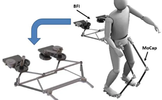
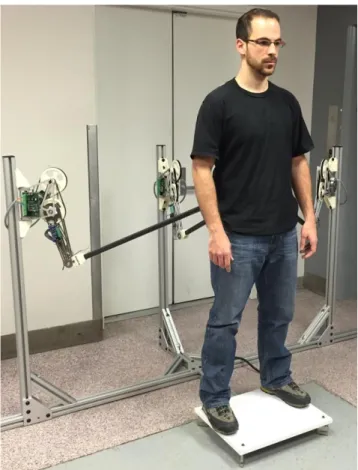
The Balance Feedback Interface (BFI) is a planar mechanism that generates forces on the human transverse plane at waist level, near the center of mass (CoM) as shown in Fig. 1. We expect that the robot’s state of balance can be transmitted to the human using this minimal input, avoiding complexity and ambiguous information. In addition to that, it is required from the BFI to: (i) be transparent to the user (backdrivable and low inertia); (ii) be nonintrusive; (iii) be instinctive (reflex-based); and (iv) use no visual input.
To estimate the necessary maximum disturbance force to be applied to the human a simple empirical procedure was conducted. For a healthy average size and weight male that would act as the robot’s typical operator, a 50N force applied sideways at the waist was found to be enough to lift one foot off the ground while standing with parallel feet in an upright position. Thus, the BFI designed is able to generate this amount of force at any direction continuously anywhere inside
its workspace. The disturbance applied to the human should be enough to trigger the situation awareness but cannot be so large that would compromise human’s ability to maintain balance.
Figure 1. The Balance Feedback Interface (BFI) is attached to the user’s waist, close to the Center of Mass. The mechanical Motion Capture (MoCap) System suit is being developed for future integration with the BFI.
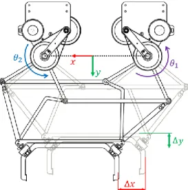
When connected to the BFI, the user is constrained to two DOF planar hip translation (transverse plane). In order to achieve this requirement a scissor-like linkage mechanism is used. The rotational motions of the two motors, 𝜃1 and 𝜃2, are converted into planar translation of the end-effector, Δ𝑥 and Δ𝑦, by coupling the intermediate joints. Fig. 2 depicts the mentioned mechanism. By mapping the system planar Jacobian, 𝐽, the torques, [𝜏1 𝜏2]𝑇, necessary to generate the required forces, [𝐹𝑥 𝐹𝑦]𝑇, at the end-effector can be calculated using
[𝜏1𝜏
2] = 𝐽 𝑇[𝐹𝑥
𝐹𝑦] This approximation can be used due to the low inertia of the linkages and transmission system. It is intended that the inertia of the operator inside of the device should dominate the dynamics.
The two degrees of freedom are actuated by two Maxon EC90 Flat 48V brushless motors with a 23:1 timing-belt reduction for minimum backlash. The motors are current controlled by Maxon ESCON 50/5 motor drivers for smooth torque tracking. Contactless Hall-Effect rotary sensors measure the motor angular position and two Transducer Techniques 25lb load cells mounted at 45º measures the actual force applied to the user.
B. Force Controller
The control law that generates the required force against the human is composed of two paths: (i) a feedforward path; and (ii) a feedback path that compensates for model errors and system losses. The block diagram for the proposed controller is shown in Fig. 3.
Figure 2. The Balance Feedback Interface: a scissor-like mechanism used to convert motor torque into planar force at the end-effector.
Figure 3. Block diagram representation of the implemented force controller. Notice the feedforward path and the proportional feedback path.
The force to be applied to the human is generated by a given reference (detailed in Section IV). This vector is mapped into torques to be command to the motors while a proportional feedback controller compensates for errors using the measurements from the load cells at the end-effector.
The controller is implemented in LabView using a National Instruments myRIO FPGA with a 2kHz control loop rate.
III. HERMES: DYNAMIC HUMANOID ROBOT HERMES is currently a 12 DOF 25kg biped robotic platform that shares the high torque density actuators technology with the MIT Cheetah Robot [12]. HERMES is designed to have anthropomorphic limbs and about 90% of the average human dimensions. We expect that this minimal size robot can naturally interact with tools and navigated environments originally designed for humans. Each foot has three built-in load cells that are responsible for measuring the ground reaction forces (GRF) and thus estimate the robot’s Center of Pressure (CoP).
Similar to humans, HERMES hip joint has three spherical DOF. The hip and knee sagittal plane actuation is performed by two coaxial high density torque brushless motors with low gear ratio (6:1); similar to those mounted on the MIT Cheetah Robot. The ankle joint two DOF are driven by a parallel mechanism actuated by two Dynamixel MX106 servo motors with 10Nm static torque capacity, see Fig. 4. All actuators are current controlled using custom drivers in order to achieve high performance torque tracking. Each leg has an outer plastic cosmetic shell with a carbon fiber square tube core. All the
actuators are located on proximal configuration in order to reduce leg inertia and perform dynamic behavior. The platform is controlled by a xPC Target Real-Time Machine.
Figure 4. HERMES Lower Body: a 12DOF (6DOF per leg) biped robotic platform.
Fig. 5 shows the geometry adopted for HERMES' feet. The triangular foot is designed to always contact the flat ground at three known points (𝐹𝑅𝑖 and 𝐹𝐿𝑖, 𝑖 = 1,2,3). Three Futek LLB400 500lb load cells are used per foot. The measured ground reaction forces at these points are weighted in order to estimate the robot’s Center of Pressure. The support polygon of the robot is defined as the geometric figure that connects all points of contact under the robots feet [10]. HERMES’ support polygon for a single foot is a triangle, however for double support stance the geometric figure can have up to six edges.
Figure 5. HERMES foot design: three load cells in each foot measure the ground reaction forces in order to measure robot’s CoP.
IV. HUMAN-MACHINE EXPERIMENTS
In order to evaluate the dynamic performance of the teleoperated platform to external disturbances the following experimental procedure is implemented: (i) the human pilot generates a position-based reference that is followed by the slave robotic platform; (ii) as the robot moves and the CoP
translates, the BFI applies proper disturbance forces on the human. With this approach we expect that postural corrective actions executed by the human will be translated into robot disturbance rejection actions.
Figure 6. Hip translation on x direction commanded by the operator during teleoperation. The robot follows a proportional reference.
A. Master Reference Generation
The teleoperation command generated by the human is defined as simple hip translation. This translation is monitored by the BFI and this information is sent to the robot by a serial communication protocol. As shown on Fig. 6, as the human performs a hip lateral translation Δ𝑥, the robot follows the same motion scaled by a tunable parameter 𝛼. A similar strategy is used to track the forward-back translation Δ𝑦. B. Force Feedback Generation
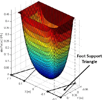
As mentioned before, the teleoperated robotic platform follows the hip translation commanded by the human operator and the robot’s CoP translates inside the support polygon. In order to inform the user that the robot’s CoP point is approaching the edge of the support polygon a potential function is implemented as shown on Fig. 7.
Properly defined in [10], if the CoP of the robot is located at the boundary of the support polygon, the mechanism is either already tilting (loosing balance) or on the edge of doing so. During the balancing experimental tests described on the following subsection, these situations must be avoided in order to maintain balancing stability.
The force applied to the human is a function of the proximity of the robot’s CoP to the edge of the support polygon. This force will increase exponentially according to the potential function on Fig. 7. For stance, on the x direction the force is defined as
𝐹𝑥= { −𝑎1𝑏.𝐶𝑜𝑃𝑥+ 1, 𝐶𝑜𝑃 𝑥≥ 0 𝑎2𝑏.𝐶𝑜𝑃𝑥− 1, 𝐶𝑜𝑃 𝑥< 0
Where 𝑎1 𝑎2, and 𝑏 are constants to be calibrated; and 𝐶𝑜𝑃𝑥 is the x position of the CoP inside the support polygon. An analogous expression is used for the force applied on the human on the y direction.
Figure 7. Potential function used for robot’s CoP translation. As the CoP approaches the edge of the support polygon the force applied to the human
increases exponentially.
Figure 8. Left: as the hammer impacts the robot on the y direction the CoP moves bacwards; Right: As the robot’s CoP reaches the limit of the support
polygon a force is applied to the human in order to transmit the impact information.
C. Experimental Setup and Results
The experiment was conducted having the human operator and the robotic platform starting at an upright stance position with both feet parallel and with full contact with the ground. Human’s hip motion is measured by the BFI end-effector position and is mapped to robot hip translation and torso bowing motion. At all times, the robot’s CoP was measured by the feet load cells and this information was processed by the BFI to generate the proper force to be applied to the operator’s waist. Notice that the user had no visual information about the robot’s posture. Moreover, the pilot was also not aware of the timing or intensity of any of the disturbances.
While the robot follows position-based postural commands given by the human pilot, the robotic platform was repeatedly hit by a rubber hammer perpendicular to the frontal plane, as shown on Fig. 8 left. This disturbance translated the robot’s CoP backwards (-y direction) and closer to the edge of the support polygon, making the robot loose balance. As the CoP translates, the BFI applies a planar force on the human’s waist according to (2), see Fig. 8 right.
Fig. 9 shows the results for the described procedure. Notice the black line represents the translation of the CoP of the robot on the y direction when the human is on the loop. The red line represent the same measurement when the robot is just standing with a prescribed joint stiffness (no human input). The rubber hammer impact can be easily verified by the deep undershoot on the CoP position (as indicated by the arrows). The edge of the support polygon on the y direction is located at the -0.06m line represented by the green mark.
The red line shows that the robot upright stance is not open loop stable. As should be expected, the robot loses balance if disturbed by large and/or constant impacts.
As estimated, when the robot’s CoP crosses the edge of the support polygon the robot loses stability and falls backwards. As can be verified on Fig. 9, the human performs reflex-based postural corrections that drive the CoP of the robot to a safe zone.
Figure 9. Robot’s reaction to external disturbances. Top: robot’s CoP translation on y direction with and without human in the loop. Bottom:
robot’s CoP translation on transverse plane.
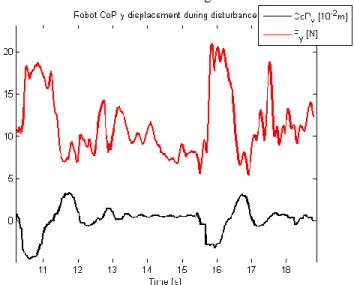
Fig. 10 shows the force, Fy, exerted on the human as the
robot’s CoP translates on the y direction. One can notice positive large disturbance on the human as the CoP oscillates undershoots.
The experiments in this study were conducted with the human as a position controller on the robot joints. Moreover,
the BFI force controller coerced the operator to move to a posture that is mapped into a stable position for the robot CoP. The control structure is shown in Fig. 11.
Figure 10. Force Fy applied to human in y direction and robot’s CoP
translation on the same axis. Notice the inverse proportionality between the two values.
Figure 11. Control architecture adopted for balancing experiments.
In this work, the operator is asked to move in the direction the force is applied by the BFI in order to balance the robot. In this case the operator’s dynamics in the control loop act as a filter with an input delay (sensorimotor response time). If, on the other hand, the force applied to the human is in the opposite direction as the motion necessary to balance the robot, we expect the human to act as a compensator. This strategy means that if the robot is about to lose balance, then the BFI attempts to pull the human out of balance as well. In this case, we hypothesize that the BFI is to trigger human’s natural response to disturbances. This strategy is to be explored on future work.
V. CONCLUSIONS
A simple control framework for bilateral feedback in biped robot teleoperation is presented. The methodology takes advantage of human’s natural reflex-based reactions in order to balance a bipedal humanoid platform during a simple standing task. The Balance Feedback Interface is a planar two DOF mechanism that is attached to user’s waist in order to inform the balancing stability of the robot. This is accomplished by applying a force that varies according to the CoP distance to the edge of the support polygon. The slave platform, HERMES, a biped robotic platform follows the
commanded postural references from the user with minimal information. To evaluate the proposed strategy, the CoP translation of the robot is evaluated under the impact disturbance of a rubber hammer. Results shows that the human operator can perform reflex-based reactions that drives the robot stability back to a safe region.
The control law adopted suggests to be very intuitive to the operator. The human pilot is able to balance the biped platform under unpredicted disturbance without prior knowledge of the robot dynamic behavior or any kind of visual input.
It is assumed that the human sensorimotor time delay plays a crucial role on the adopted strategy [13]. For quasi-static tasks the balancing stability can be easily achieved by the framework adopted. But it is still unclear how the whole system responds to highly dynamic motions and further investigation is necessary.
VI. FUTURE WORK
By no means the proposed controller intends to replace existing autonomous balancing controllers implemented on legged platforms. This study aims to push the limits of how much aid the human can provide as a reflex-based controller and teleoperator, provided the information about the robot’s state of balance. It is still unclear how far the user can synchronize his own motor actions with the robots motion. However it is known that humans are highly adaptive systems and we expect to reveal new possibilities on teleoperation by giving the human information about the robot’s interaction with the surroundings. The long term goal of this project is to merge human flexibility and adaptability capacity with an autonomous controller, taking advantage of the best of both methods.
Motivated by the results from this preliminary approach we are currently developing a six DOF (three actuated) parallel mechanism that offers no constraint to human’s hip motion. The device’s design is composed of three modular actuators as shown on Fig.12. In addition to that, a mechanical MoCap system is to be used in order to track human’s posture and transmit precise motion intentions to the robot.
Future works aims to integrate the robot’s upper limbs in the balance control strategy, adding robustness to disturbance rejection. The upper limbs are to be used in two different ways: (i) as a reaction inertia to cancel impulsive force to the torso [14], [15]; and (ii) to offer a last resort on stability if the robot is to fall (quadruped mode) [10].
Finally, we aim to characterize the whole system time delay effect on the teleoperation task. It is expected that the human response time delay and the computer communication/control rate should introduce undesired dynamics to the system [16].
Thus, it is necessary to classify the stability margin allowed for the robot to follow the user’s dynamic movements.
Figure 12. The six DOF modular parallel mechanism for unconstraint human motion. Three actuators can redundantly generate force on the
transverse plane.
REFERENCES
[1] NHK Documentary: “Robot Revolution: Will Machines Surpass
Humans”, May 2013.
[2] The Robotics Challenge: http://www.theroboticschallenge.org/
[3] S. K. Kim, S. Hong, D. Kim, “A Walking Motion Imitation Framework
of a Humanoid Robot by Human Walking Recognition from IMU
Motion Data”, in Humanoid Robots, 9th IEEE/RAS International
Conference on, IEEE, 2009.
[4] J. Koenemann, F. Burget, M. Bennewitz, “Real-time Imitation of
Human Whole-Body Motions by Humanoids”, in Robotics and Automation (ICRA), 2014 IEEE International Conference on, 2014.
[5] E. Neo, K. Yokoi, S. Kajita, K. Tanie, “Whole-Body Motion Generation
Integrating Operator’s Intention and Robot’s Autonomy in Controlling Humanoid Robots”, IEEE Trans. On Robotics, Vol., 23, No. 4, 2007.
[6] T. Takubo, K. Inoue, T. Arai,. “Whole-body Teleoperation for
Humanoid Robot by Marionette System”, in Intelligent Robots and Systems (IROS) 2006 IEEE/RSJ International Conference on. IEEE,
2006.
[7] R. Chipalkatty, H. Daepp, M. Egerstedt, “Human-in-the-Loop: MPC
for Shared Control of a Quadruped Rescue Robot”, in Intelligent Robots and Systems (IROS) 2011 IEEE/RSJ International Conference on. IEEE, 2011.
[8] S. Anderson, C. Atkeson, A. Mahboobin, P. Loughlin, M. Redfern, “Sensory Adaptation in Human Balance Control: Lessons for
Biomimetic Robotic Bipeds”, Carnegie Mellon University Robotics
[9] E. Burdet, D. W. Franklin, T. E. Milner – Human Robotics:
Neuromechanics and Motor Control, The MIT Press, 2013.
[10] M. Vukobratovic, B. Borovac, “Zero-Moment Point – Thirty Five Years
of its Life”, Internatonal Journal of Humanoid Robotics, Vol. 1, No. 1,
pp157-173, 2004.
[11] S. Seok, A. Wang, M. Y. Chuah, D. Otten, J. Lang, S. Kim, “Design
Principles for Highly Efficient Quadrupeds and Implementation on the MIT Cheetah Robot”, in Robotics and Automation (ICRA), 2013 IEEE International Conference on, 2013.
[12] S. Seok., A. Wang, , D. Otten, S. Kim, ”Actuator Design for High Force
Proprioceptive Control in Fast Legged Locomotion”, in Intelligent Robots and Systems (IROS) 2012 IEEE/RSJ International Conference on. IEEE, 2012, pp. 1970-1975.
[13] K. Kuchenbecker, N. Gurari, Al. Okamura, “Effects of Visual and
Proprioceptive Motion Feedback on Human Control Targeted
Movement”, in Rehabilitation Robotics, 2007 IEEE 10th International
Conference on. IEEE, 2007.
[14] D. Orin, A. Goswami, S. Lee, “Centroidal Dynamics of a Humanoid
Robot”, Journal on Autonomous Robots, Vol. 35, Issue 2-3, pp.
161-167, 2013.
[15] S. Yun, A. Goswami, “Momentum-Based Reactive Stepping Controller
on Level and Non-Level Ground for Humanoid Robot Push Recovery”,
in Intelligent Robots and Systems (IROS) 2011 IEEE/RSJ International
Conference on. IEEE, 2011.
[16] M. Lakie, D. Loram, “Manually Controlled Human Balancing Using
Visual, Vestibular and Proprioceptive Senses Involves a Common, Low Frequency Neural Process”, J. Physiology, 577.1, 33. 403-416, 2006.
[17] S. Nakaoka, A. Nakazawa, F. Kanehiro, K. Kaneko, M. Morisawa, K. Itekeuchi, “Task Model of Lower Body Motion for Biped Humanoid to
Imitate Human Dances”, in Intelligent Robots and Systems (IROS) 2005 IEEE/RSJ International Conference on. IEEE, pp 3157-3162, 2005.
[18] S. Kim, C. Kim, B. You, S. Oh, “Stable Whole-Body Motion Generation
for Humanoid Robots to Imitate Human Motions”, in Intelligent Robots and Systems (IROS) 2009 IEEE/RSJ International Conference on.
IEEE, 2009.
[19] J. Babic, J. Hale, E. Oztop, “Human Sensorimotor Learning for
Humanoid Robot Skill Synthesis”, Adaptive Behavior, SAGE, pp.
250-263, 2011.
[20] B. Stephens, C. Atkeson, “Dynamic Balance Force Control for
Compliant Humanoid Robots”, in Intelligent Robots and Systems (IROS) 2010 IEEE/RSJ International Conference on. IEEE, pp
1248-1255, 2010.
[21] K. Pipereit, O. Bock, J. L. Vercher, “The Contribution of
Proprioceptive Feedback to Sensorimotor Adaptation”, Experimental
Brain Research, Springer-Verlag, Vol. 174, Issue 1, pp. 45-52, 2006. [22] H. Daepp, W. Book, “User Interface with Multisensory Feedback for
Fluid Powered Rescue Robot”, Proceedings of the 6th FPNI – PhD
Symposium, Georgia Institute of Technology, 2010.
[23] R. T. Peterka, “Sensorimotor Integration in Human Postural Control”, J. of Physiology, 88.3, pp. 1097-118, 2002.
[24] S. Kajita, F. Kanehiro, K. Kaneko, K. Fujiwara, K. Harada,. K. Yokoi, H. Hirukawa, “Resolved Momentum Control: Humanoid Motion
Planning based on the Linear and Angular Momentum”, in Intelligent Robots and Systems (IROS) 2003 IEEE/RSJ International Conference on. IEEE, 2003.
[25] S. Lee, A. Goswami, “A Momentum-Based Balance Controller for
Humanoid Robots on Non-Level and Non-Stationary Ground”, Journal