Publisher’s version / Version de l'éditeur:
Vous avez des questions? Nous pouvons vous aider. Pour communiquer directement avec un auteur, consultez la première page de la revue dans laquelle son article a été publié afin de trouver ses coordonnées. Si vous n’arrivez pas à les repérer, communiquez avec nous à PublicationsArchive-ArchivesPublications@nrc-cnrc.gc.ca.
Questions? Contact the NRC Publications Archive team at
PublicationsArchive-ArchivesPublications@nrc-cnrc.gc.ca. If you wish to email the authors directly, please see the first page of the publication for their contact information.
https://publications-cnrc.canada.ca/fra/droits
L’accès à ce site Web et l’utilisation de son contenu sont assujettis aux conditions présentées dans le site LISEZ CES CONDITIONS ATTENTIVEMENT AVANT D’UTILISER CE SITE WEB.
Annual Conference of the Canadian Society for Civil Engineering 2011: Ottawa,
Ontario, Canada, 14-17 June 2011, 2, pp. 1188-1197, 2011-06-14
READ THESE TERMS AND CONDITIONS CAREFULLY BEFORE USING THIS WEBSITE. https://nrc-publications.canada.ca/eng/copyright
NRC Publications Archive Record / Notice des Archives des publications du CNRC :
https://nrc-publications.canada.ca/eng/view/object/?id=14e9fdab-2699-4748-9d6e-0fabeb5e0da0
https://publications-cnrc.canada.ca/fra/voir/objet/?id=14e9fdab-2699-4748-9d6e-0fabeb5e0da0
NRC Publications Archive
Archives des publications du CNRC
This publication could be one of several versions: author’s original, accepted manuscript or the publisher’s version. / La version de cette publication peut être l’une des suivantes : la version prépublication de l’auteur, la version acceptée du manuscrit ou la version de l’éditeur.
Access and use of this website and the material on it are subject to the Terms and Conditions set forth at
Combined effect of reinforcement corrosion and seismic loads on RC
bridge columns: modelling
Com bine d e ffe c t of re inforc e m e nt c orrosion a nd se ism ic loa ds on RC
bridge c olum ns: m ode lling
N R C C - 5 4 4 5 6
M o h a m m e d , A . M . ; A l m a n s o u r , H . ; M a r t i n - P é r e z ,
B .
J u n e 2 0 1 1
A version of this document is published in / Une version de ce document se trouve dans:
2nd International Engineering Mechanics and Materials Specialty Conference
Ottawa, Ontario, June 14-17, 2011, pp. 1-10
http://www.nrc-cnrc.gc.ca/irc
The material in this document is covered by the provisions of the Copyright Act, by Canadian laws, policies, regulations and international agreements. Such provisions serve to identify the information source and, in specific instances, to prohibit reproduction of materials without written permission. For more information visit http://laws.justice.gc.ca/en/showtdm/cs/C-42
Les renseignements dans ce document sont protégés par la Loi sur le droit d'auteur, par les lois, les politiques et les règlements du Canada et des accords internationaux. Ces dispositions permettent d'identifier la source de l'information et, dans certains cas, d'interdire la copie de documents sans permission écrite. Pour obtenir de plus amples renseignements : http://lois.justice.gc.ca/fr/showtdm/cs/C-42
EM-033-1
Combined Effect of Reinforcement Corrosion and Seismic Loads on
RC Bridge Columns: Modelling
A.M. Mohammed
1, H.H. Almansour
2, and B. Martín-Pérez
1 1Department of Civil Engineering, University of Ottawa, Ottawa, Ontario, Canada
2
Institute for Research in Construction, National Research Council Canada, Ottawa, Ontario, Canada
Abstract: Columns are often the most vulnerable elements in reinforced concrete (RC) bridges as their
failure could lead to bridge collapse. Characteristically, columns are subjected to combined static and dynamic eccentric and lateral forces due to traffic, self-weight, and earthquake loads. For the assessment of bridge columns in seismic areas, it is essential to evaluate their state of damage, strength and deformation capacity over their service life. In this paper, a nonlinear elasto-plastic numerical model to simulate bridge columns under the combined effects of reinforcement corrosion and seismic excitation is presented. The study includes the development of a comprehensive and yet simple tool to evaluate the seismic performance, and the residual strength and deformation capacity of aging RC bridge columns suffering from reinforcement corrosion. The model enables evaluating aging and deteriorated RC bridge columns safety, the decline in their energy dissipation capability, and the level of earthquake excitation that they may survive. Hence, the model can represent a useful tool for bridge engineers to optimize the use of available resources and define the critical capacity of bridge columns against earthquake events. It is found that the model is efficient in simulating the behaviour of the column under corrosion and seismic loads. From the case study, it is found that the load carrying capacity of the corroded column is much lower than that of non-corroded columns. The results show significant reduction in the column displacement capacity and energy dissipation capability due to rebar corrosion. The corrosion-induced damage could result in accelerated degradation of the bridge columns and reduce its ultimate strength.
1. Introduction
Columns are often the most vulnerable elements in reinforced concrete (RC) bridges as their failure could lead to bridge collapse. Characteristically, columns are subjected to combined static and dynamic eccentric and lateral forces due to traffic, self-weight and earthquake loads. For the assessment of bridge columns in seismic areas, it is essential to evaluate their state of damage, strength and deformation capacity over their service life. In bridge design codes the major concern is the bridge serviceability and safety under applied loads, including seismic loads, without an explicit attempt to account for deterioration. However, RC bridge columns in cold regions are affected by chloride-induced reinforcement corrosion, generated mainly from the application of de-icing salts in the winter. Hence, in the evaluation of RC columns of aging bridges, where reinforcing steel corrosion is a potential or on-going problem, the main goal is to determine the capacity of the deteriorated RC columns, their safety margin related to the load demand, and whether or not this capacity will further decline over time.
Reinforcing steel corrosion is a long-term process with accumulated influence, while seismic loads are accidental by nature. The interaction and combination of both loads could be a result of two possible scenarios: (i) corrosion is in progress or in an advanced stage and an earthquake occurs; or (ii) the structure survived a medium size earthquake with some minor damage in the form of cracks, which could accelerate the initiation or the progress of the corrosion process. Whereas the first case is important in evaluating the safety and capacity of the structure under seismic load, the second case is important in elevating the alert to accelerate the bridge inspection-evaluation cycle.
EM-033-2
Saito et al. (2007) presented the fundamental properties of strength and deformation capacity of corroded RC columns subjected to seismic load. The study had two set of specimens: (i) columns subjected to axial compression load only; and (ii) columns that were exposed to axial compression and cyclic lateral load. In both tests, the studied parameters were the length of corroded reinforcing bar, the corrosion simulation method, and the corrosion level. They observed that the corrosion of longitudinal bars and hoops causes reduction in the column deformation capacity. They proposed a stress-strain model and corresponding deformation capacity by considering the reduction of cross section of corroded reinforcing bars. Attributed to the lack of the theoretical data and relevant information, this study did not give attention to the deteriorated concrete elements performance under dynamic load. Choe et al. (2008) developed probabilistic drift and shear force capacity models by integrating the effects of deterioration of corroded structural elements into a structural capacity model. In their study, a numerical approach was performed using the OpenSees software to obtain the fragility estimate for a given column, which was modeled by fiber-discretized cross sections, where each fibre contains a uniaxial inelastic material model. Also, the probabilistic model for reinforcement corrosion (corrosion initiation, corrosion rate, and loss of cross-section area) was carried out to characterize the prediction of service life of existing and new structures and their life-cycle cost analysis. The numerical study calculated that at the beginning of the corrosion propagation phase, the sensitivity with respect to the structural capacity parameter model increased only in the first year of the corrosion propagation, decreased around the time of transition from the diffusion phase and the corrosion phase, and thereafter it increased gradually. Berto et al. (2009) conducted a theoretical investigation to assess the corrosion effects on the seismic behaviour of RC structures. The assessment processes were carried out under a moderate corrosive attack taking into account two parameters: reinforcing bars section reduction and concrete cover degradation. A nonlinear static analysis was performed using MIDAS Gen software, by considering gravitational and seismic loads and representing the structure by the lumped plasticity approach. The work of Choe et al. (2008) and Berto et al. (2009) are more focused on the consideration of loss of the reinforcement cross-sectional area in order to evaluate the structural capacity model. It is attributed to the lack of experimental tests and to the difficulty of developing simple numerical models to simulate the real behaviour of corroded structures.
The goal of this paper is to present a numerical model to evaluate the combined effects of corrosion-induced damage and seismic load on the performance of RC bridge columns. The emphasis is on the time frames diversity between the two processes and the instantaneous seismic capacity of an aging column. The procedure includes an external cycle to represent the corrosion process, which is introduced through the reduction of the reinforcing steel area and ductility and concrete cover. Step-by-step integration for the time-history analysis and the hysteretic behaviour of the RC column is then performed using an efficient algorithm.
2. Research Significance
This paper presents a nonlinear elasto-plastic numerical model to simulate bridge columns under the combined effects of reinforcement corrosion and seismic excitation. The contribution of this study includes the development of a comprehensive and yet simple tool to evaluate the seismic performance and the residual strength and deformation capacity of aging RC bridge columns affected by reinforcement corrosion. This numerical tool enables the evaluation of aging and deteriorated RC bridge columns safety, the decline in their energy dissipation mechanism, and the level of earthquake excitation that they may survive. Hence, the model can represent a useful tool for bridge engineers to optimize the use of available resources and define the critical capacity of bridge columns against earthquake events.
3. Proposed Model
Figure 1 shows a flowchart of the proposed model. The model involves six major parts: (i) input data; (ii) formulation of the structure and load matrices; (iii) static and dynamic analyses, wherein the traffic loads are included; (iv) corrosion process; (v) time-history analysis under earthquake load; and, (vi) results. The procedure includes an external cycle to represent the corrosion process, which is activated once the
EM-033-3
corrosion activation parameter is equal to 1. The corrosion cycle starts at time Tcor1 and ends at time T cor-final with time increment of ∆tcor. During every corrosion time-increment, a time-history analysis of the
column is performed if desired (by activating the seismic parameter, or seismic=1, in the input data). The procedure starts with the input data of: (i) the structure, which includes geometrical and material characteristics and boundary conditions; and (ii) control parameters. The results for the column performance are printed with reference to each selected time increment or selected ones.
Start Corrosion=1 Form Element Stiffness [K] and Mass Matrices [M], Assembly K,M and load vector, Apply B.C
Static & Dynamic Analysis due to Traffic Load DRAIN-RC N N Apply Corrosion Model Y
Input Data: Geometrical, Materials , Corrosion &
Seismic
Tcor= Tcor1
Seismic=1
Print time history and hysteretic behavior
Stop Tcor≤ Tcor-final
Print End of Corrosion Process Tcor=Tcor+Δtcor
Corrosion =1 No Corrosion Process Y N N Y Y
Figure 1: Proposed model for combined effects of corrosion and seismic loads
3.1 Bridge Structure
Since the focus of this study is on the behaviour of bridge columns, the considered structure is a slab-on-girder bridge (which is usually simply supported on piers or abutment), Figure 2-a. Also, it is essential to model both the superstructure and substructure as one structural system. The model is required to effectively simulate the integration of the two parts. In slab-on-girder bridges and assuming practical girder spacing, the traffic load distribution in the lateral direction (orthogonal to the traffic direction) can be assumed uniform, and, hence, the bridge is modelled as a two-dimensional frame (Figure 2-b). The frame in this model is basically formed from a beam, representing the superstructure, and two piers. The connections between the beam and the piers are represented by an internal hinge on one side and a roller on the other side. The model also accounts for possible eccentricity in both connections. The base of the two piers is assumed fully fixed. For the purpose of calculating the beam properties, the slab is assumed to be compositely connected to the girders. In the present model, the lateral slab flexural action
EM-033-4
and the girders tensional rigidities are ignored. Each pier consists of a cap beam, where the bridge superstructure girders rest on, and supporting columns forming a frame. In order to include the effect of reinforcement loss when corrosion is applied, the column is considered as a composite section. The beam and the columns are modeled using a beam-column element with three degrees of freedom per node. The damping matrix is derived assuming a linear proportion between damping of the elements and their mass and stiffness.
Figure 2-a: 3-D bridge system Figure 2-b: 2-D bridge system
3.2 Nonlinear Modelling and Time-History Analysis
The computer program developed in this study is integrated with the computer program DRAIN-RC, which is used to perform inelastic dynamic history analysis as shown in Figure 1. The original version of the program (DRAIN-2D) was developed by Kanaan and Powell (1973) to conduct dynamic analysis of inelastic plane structures. The program was modified by Alsiwat (1993) and Shoostari (1998) by adding new hysteretic models for shear and anchorage slip and including new features such as inelastic static analysis (push-over) and P-Δ effects. In DRAIN, the structure is discretized into a number of elements with degrees of freedom at the nodes. Each node can have up to three degrees of freedom, two translations and one rotation, and provisions are made for restraining either degree of freedom. The global stiffness of the structure is assembled from individual element stiffness using the direct stiffness method, whereas the mass of the structure is assumed lumped at the joints resulting in a diagonal mass matrix. Damping can be specified as either mass dependent or stiffness dependent Raleigh damping. Ground motion is entered as accelerations specified at constant time intervals and can differ for horizontal and vertical directions.The dynamic response is determined using a step-by-step integration technique, with the assumption of constant average acceleration during each time step. In assembling the stiffness matrix, the tangent stiffness at the beginning of each step is assumed to remain constant during the step. The stiffness of each element is updated at the beginning of each step, and if the nonlinear analysis option is selected, errors due to possible overshooting are corrected by applying a corrective load at the beginning of the next step.
3.3 Corrosion Load
The effect of reinforcement corrosion is modelled here by reducing the rebar cross-sectional area over time. The change in the RC elements sectional properties (area and moment of inertia) leads to a reduction in their stiffness. The loss of reinforcing steel due to corrosion is evaluated by applying Faraday’s law, from which the thickness reduction x(t) of the reinforcing bar after time t can be calculated according to Eq. 1: [1] = ⋅ ⋅ ρ corr s M x(t) i t zF
where M is the metal molar mass (55.85 g/mol for iron), z is the valence of the ion formed as a result of iron oxidation (i.e., z = 2 for Fe → Fe2+ + 2e-), F is Faraday’s constant (F = 96,485 C/mol), ρs is the
density of iron (ρs = 7.85 g/cm 3
), icorr is the corrosion current density, and t is the time elapsed since
corrosion started. By substituting the values of M, z, F and ρs into Eq. 1, the rate of thickness reduction
EM-033-5
results in x(t)=0.0116 i⋅corr⋅t, where x(t) is given in mm, icorr is given in µA/cm 2
, and t is given in years. Although Faraday’s law assumes that all electrical current is used up by the corrosion process, it gives a conservative estimate of the steel loss due to corrosion. The depth of the corrosive penetration attack p(t) is calculated from:
[2] p(t)= ⋅R x(t)= ⋅R 0.0116 i⋅corr⋅ t
where R is the ratio between the maximum penetration of a pit p(t) (Figure 3-a) and average penetration x(t) corresponding to uniform corrosion (Figure 3-b). Parameter R is also known as the pitting ratio. Val (2007) has reported that the maximum penetration of pitting on the surface of a rebar is about 4-8 times the average penetration corresponding to uniform corrosion. Assuming that the pit can be idealized as a hemisphere, as illustrated in Figure 3-a, the cross-sectional area As(t) of a group of n reinforcing bars
after t years of corrosion can be estimated as:
[3] 2 n o s p,i i 1 D A (t) n A (t) 0.0 4 = π = −
∑
≥where Do is the initial reinforcing bar diameter and Ap,i(t) is the cross-sectional area of a pit after time t,
which is a function of p(t) and calculated according to Val (2007). Corrosion-induced damage is also simulated by assuming that the concrete cover of the columns has spalled out (Figure 3-c).
(a) Pit configuration (adapted from Val, 2007) (b) Uniform corrosion (c) Spalling of the concrete cover Figure 3: Corrosion model
The ductility of reinforcing bars has also been observed to be affected by corrosion. Many empirical models for loss of ductility have been proposed. Lay and Schiebl (2003) and Cairns et al. (2005) have established the following empirical equations to assess indirectly the residual ductility of reinforcement due to corrosion:
[4] f (t)y =
(
1.0− α ⋅y As( )
t f)
y [5] f (t)u =(
1.0− α ⋅u As( )
t f)
uwhere fy(t) is the yield strength at time t, fu(t) is the ultimate tensile strength at time t, fy and fu are the yield
and ultimate tensile strengths of a non-corroded bar, respectively, As(t) is the cross section loss as a
function of time t, and αy, αu are regression coefficients (Lay and Schiebl 2003).
Removal of concrete cover
Do
x(t)
EM-033-6
It is worth noting that bond degradation due to reinforcing steel corrosion might become a concern for RC bridge columns located in seismic areas. The model presented here ignores these effects for the sake of simplicity.The effect of bond degradation due to corrosion on the seismic performance is not considered in this paper and will be included in the next phase of this research.
4. Load Combination and Interaction
The focus of the current study is on the combined effect of reinforcement corrosion and seismic load on highway bridge columns. However, the possible combination of other loads, such as self load and traffic loads has to be also taken into account. From the modeling point of view, three scenarios of bridge loading combination during an earthquake are possible: (i) earthquake and permanent loads (earthquake occurs when there is no traffic on the bridge); (ii) earthquake and full traffic loads (earthquake occurs during rush hour); (iii) earthquake and one truck (or more) is moving on the bridge. In the second scenario, the traffic load can be considered as static load (or multi lane loading). In the last scenario and for short span bridges, the duration of an earthquake is much longer than the time required for a truck to pass the bridge with a design velocity of 100 km/h. However, the frequency and the amplitude of the bridge vibration due to earthquake excitation is very high compared to the bridge vibration due to single or multiple trucks passing the bridge at the same time. The dynamic interaction between the resulting vibrations due to both excitations is relatively complicated and out of the scope of the present study. Therefore, when combining the earthquake and corrosion loads, the traffic load is simplified as an equivalent static load (taking into account the dynamic impact factor) or taken as a dynamic excitation of two-degrees of freedom system (see Mohammed et al 2010), ignoring the dynamic interaction between the traffic and the earthquake.
The proposed model, as illustrated in Figure 1, analyzes the combined effects of different loads; the two main subroutines (corrosion and DRAIN-RC) are to be called through the main program. Individual and/or combined analysis can be selected. DRAIN-RC imports the input data file already created by the main program. The main program controls the DRAIN-RC solver and runs each analysis step and extracts DRAIN-RC results. The extracted analysis results are then processed by the main program, providing the predicted corrosion-induced damage and the seismic performance of the column related to the instantaneous stage of corrosion (if requested in the input data).
5. Case Study
The proposed model is examined through a case study of a slab-on-steel girder bridge with center to center span of 49.1 m. The bridge is simply supported on RC piers formed from eight rectangular 600×400 mm columns, connected from the top to a beam where the bridge superstructure girders rest on. The 6.0 m high columns are assumed to have full fixity at the foundation level. Detailed properties of the bridge superstructure are given in Table 1. The concrete compressive strength f’c for all the concrete
components of the bridge is assumed equal to 30 MPa.
A one-dimensional bridge substructure system is analyzed under a load combination consistent with CHBDC 2006 (CAN/CSA-S6-00), wherein the traffic load has to be taken as 50% of the equivalent static service level (for single truck and lane loading). The seismic load is also taken into account. The one-dimensional static analysis is conducted using preliminary column dimensions to determine values of bending moment and axial forces at each column. These values are used to design the columns. Multiple cycles of analysis and design are necessary to reach an optimum size of the pier and the columns.
Table 1: General properties of slab-on-steel girder bridge Type of girder Year Built Skew Angle º Span Length m Girder Spacing m
Girder Properties Transverse width m Slab Thick m No. of Girders A m2 I m4 H m
EM-033-7
Steel 1977 0.0 49.11 2.64 0.0496 0.0187 2.898 20.487 0.2159 8
6. Results and Discussion
Field surveys have shown that the most critical sections of bridge columns, which are suffering from corrosion, are the top (drain zone) and bottom (splash zone) sections (Andersen 1997). For this study, it is assumed that the bottom section at the traffic level under the bridge is at 2.0 m above the column base, and the top section is at 6.0 m above the bridge base. Figure 4 illustrates the cross section of the RC column. Corrosion-induced damage is simulated by assuming a steel mass loss of 30%, which is equivalent to 10 years of corrosion with a corrosion current density of 1 µA/cm2. The reduction of the concrete cross section due to spalling of the concrete cover and the reduction in the ductility of reinforcing bars are also considered.
The specified ground motion record used plays an important role in attaining realistic results. It is possible that two different earthquakes with the same intensity excite a given structure differently. Therefore, the correlation between the response spectrum of a given earthquake record and the fundamental period of the structure is very important in selecting an earthquake record that is used in the analysis and results in comprehensive structural performance. In the present study, condensed data of a short Ottawa earthquake record is used as shown in Figure 5.Detailed investigation to evaluate the sensitivity of the proposed model to different earthquake records is currently on-going.
Figure 4: Column section Figure 5: Earthquake record used
The loss of the cross section of the column due to concrete spalling as well as the reduction in the area and ductility of the reinforcing steel lead to a reduction in the load carrying capacity of the column. As shown in Figure 6, the load-deformation relationship of the corroded section is much lower than that of the uncorroded section. The yield moment is reduced from 380 kN·m to 274 kN·m, and the displacement ductility is also reduced from 3.8 to 3.2. Figure 7 shows the interaction diagram of the considered column at the cross section where corrosion results in a significant decrease of the column capacity. The ultimate limit state is not satisfied in this case, as the column capacity is less than the applied factored axial load and moment, which are 2,900 kN and 244 kN·m, respectively.
EM-033-8 Figure 6: Moment-deflection curve of the
bridge column section
Figure 7: Interaction diagram of the bridge column section
Since both the steel area and concrete cover of the column at the critical cross section are reduced, their losses have a significant effect on the column stiffness. Depending on the inelastic behaviour of the column, the corroded section of the column will have less deformation capacity than the non-corroded section. With the reduction in the column flexural stiffness and the reduction in the reinforcing steel ductility, the lateral displacement history of the corroded section is increased when the bridge is subjected to seismic load. Figures 8 and 9 respectively show the significant successive increases in the lateral displacement through the time history of the corroded bottom and top column sections compared to the original non-corroded sections.
Figure 8: Lateral displacement of the bottom section of the bridge column
Figure 9: Lateral displacement of the top section of the bridge column
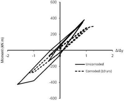
Figure 10 shows the moment-displacement history of the corroded and uncorroded bottom section of the column. The area inside the hysteretic loop is considered as an indirect measure of the energy dissipated by the plastic hinge. It is obvious that the corrosion of the longitudinal reinforcement results in significant degradation in the ultimate flexural capacity of the column and its capability to dissipate energy.
EM-033-9
Figure 10: Moment-displacement of the bottom section of the column
The ductility index of the column, which represents the ability of the column to withstand the ground motion with sufficient deformation capacity, can be computed in the DRAIN-RC subroutine of the proposed model. The results show that the corroded section possesses a lower ductility (2.9) compared to that of a non-corroded section (4.1).
The experimental investigation carried by Rodríguez et al. (1996) showed that the reduction in the concrete cover results in an added eccentricity of the applied axial load. There is also an eccentricity due to discontinuity in the superstructure/substructure joints. If the effects of these two eccentricities are combined with those of an earthquake, then the influence of the corrosion of the longitudinal reinforcement on the column ultimate capacity is further magnified.
7. Summary and Conclusions
In this paper, a nonlinear elasto-plastic numerical model to simulate bridge columns under combined effects of reinforcement corrosion and seismic excitation is presented. The study includes the development of a comprehensive and simple tool to evaluate the seismic performance and the residual strength and deformation capacity of aging RC bridge columns with corroding reinforcement. This approach enables evaluating aging and deteriorated RC bridge columns safety, the decline in their energy dissipation capability, and the level of earthquake excitation that they may survive. Hence, the model can represent a strong tool for bridge engineers to optimize the use of available resources and define the critical capacity of bridge columns against earthquake events.
The proposed procedure includes an external cycle to represent the corrosion process, which is introduced through the reduction of the cross sectional area and the ductility of the reinforcing steel and the decrease in concrete cover. Step-by-step integration is then used for the time-history analysis and the hysteretic behaviour of the RC column.
The individual and combined effects of seismic and corrosion loads have been investigated on a 49.0 m slab-on-steel girder bridge on concrete piers. It is found that the model is efficient in simulating the
EM-033-10
behaviour of the column under corrosion and seismic loads. From the case study, it is found that the load carrying capacity of the corroded column is much lower than that of the uncorroded column. The results show significant reduction in the column displacement capacity and energy dissipation capability. The corrosion-induced damage could result in accelerated degradation of the bridge columns and reduce its ultimate strength.
8. Future Work
Thorough investigation is to be performed to evaluate the effects of different values of various geometric, loading and corrosion parameters on the structural behaviour and capacity of RC bridge columns. This can be achieved by using different superstructure materials and stiffness, column design, and different levels of corrosion intensity. This analysis leads to the assessment of the safety, ductility and failure mode of aging RC bridge columns that are suffering from corrosion-induced damage. On the other hand, the predictions of this model need to be validated by comparison to experimental results obtained from scaled models of bridges tested under experimental combined axial and flexural loads of static and dynamic analyses. The interaction between the bond degradation due to corrosion and seismic performance of the columns is to be evaluated in next phase of this study.
9. References
Alsiwati, J. 1993. Effect of anchorage slip and inelastic shear on seismic response of reinforced concrete frames. Ph.D. Thesis, Dept. of Civil Engineering, University of Ottawa, Ottawa, 367 pp.
Andersen, A. 1997. HETEK, Investigation of Chloride Penetration into Bridge Columns Exposed to De-Icing Salt. Copenhagen, Denmark.
Berto, L., Vitaliani, R., Saetta, A., and Simion, P. 2009. Seismic Assessment of Existing Structures Affected by Degradation Phenomena. Structural Safety, 31(4): 284-297.
Cairns, J., Plizzari, G. A., Du, Y., Law, D. W., Franzoni. 2005. Mechanical properties of corrosion reinforcement. ACI Materials Journal, 102(4): 256-264.
CAN/CSA S6-06. 2006. Canadian Highway Bridge Design Code, Canadian Standards Association, Mississauga, ON, 800 pp.
Choe, D.-F., Gardoni, P., Rosowsky, D., Haukaas, T. 2008. Probabilistic capacity models and seismic fragility estimates for RC columns subject to corrosion. Reliability Engineering and System Safety, 93(3): 383-393.
Kanaan, A., E., and Powell, G. H. 1973. Drain-2D User’s Manual, Earthquake Engineering Research Center, Report No. EERC 73-22, University of California, Berkeley.
Lay, S. and Schiebl, P. 2003. Life cycle Management of concrete Infrastructures for improved Sustainability. European Community Fifth Framework Program: GROWTH.
Mohammed, A., Almansour, H, and Martín-Pérez, B. 2010. Modelling RC bridge columns under the combined effects of traffic and reinforcement corrosion. 8th International Conference on Short & Medium Span Bridges, Niagara Falls, Ontario, Canada, Paper 168, 10 pp.
Rodríguez, J., Ortega, L. M. and Casal, J. 1996. Load Bearing Capacity of Concrete Columns with Corroded Reinforcement. Corrosion of Reinforcement in Concrete Construction, Royal Society of Chemistry: 220-230.
Saito, Y., Oyado, M., Kanakubo, T. and Yamamoto, Y. 2007. Structural performance of corroded RC column under uniaxial compression load. First International Workshop on Performance, Protection &
Strengthening of Structures under Extreme Loading, Whistler, Canada.
Shooshtari, A. 1998. Seismic drift demands of reinforced concrete building. Ph.D. Thesis, Dept. of Civil Engineering, University of Ottawa, Ottawa, 385 pp.
Val, D.V. 2007. Deterioration of Strength of RC Beam Due to Corrosion and its Influence on Beam Reliability. Journal of Structural Engineering, 133(9): 1297-1306.