Dynamic Nuclear Polarization of Amorphous and Crystalline Small Molecules by
Ta-Chung Ong B.A., Colby College (2007)
Submitted to the Department of Chemistry
in Partial Fulfillment of the Requirement for the Degree of Doctor of Philosophy
at the
MASSACHUSETTS INSTITUTE OF TECHNOLOGY
MASSACHUSETS NTfTE OF TECHNOLOGY
JUN
3
0 2014
LIBRARIES
June 2014
C 2014 Massachusetts Institute of Technology. All rights reserved.
Signature redacted
Signature of Author... ... Department of Chemistry June 1, 2014Signature redacted
Certified by ... V Robert G. Griffin Professor of Chemistry Thesis SupervisorSignature redacted
Accepted by ... Robert W. Field Professor of Chemistry Chairman, Departmental Committee on Graduate StudentsThis doctoral thesis has been examined by a Committee of the Department of Chemistry as follows:
S
Professor Sylvia T. Ceyer... Chair
Professor Robert G. Griffin... Thesis Supervisor
ignature redacted
I
Signature redacted
Signature redacted
Professor Robert W. Field...
Dynamic Nuclear Polarization of Amorphous and Crystalline Small Molecules by
Ta-Chung Ong
Submitted to the Department of Chemistry
on June 1, 2014 in Partial Fulfillment of the Requirement for the Degree of Doctor of Philosophy in Chemistry
ABSTRACT
Solid-state NMR has emerged to become an important technique in the studies of pharmaceutical formulations consisting of active pharmaceutical ingredients (API) and excipients. Dynamic nuclear polarization (DNP), which improves NMR sensitivity by 2-3 orders of magnitude, can potentially reduce the necessary experimental time for formulations that have low API contents. However, conventionally DNP samples are prepared in cryoprotecting glassing agents such as glycerol/water or DMSO/water, which may not be suitable for studies of pharmaceuticals. In this thesis, we examined the performance of solvent-free DNP in amorphous and crystalline ortho-terphenyl (OTP) in order to gauge the feasibility of applying DNP to pharmaceutical solid-state NMR experiments and to study the effect of inter-molecular structure, or lack thereof, on the DNP enhancement. We found that while DNP of amorphous OTP benefits from greater signal enhancement due to a more homogeneous distribution of radical polarization agent, DNP of crystalline OTP features better spectral resolution but requires heavy deuteration to attenuate proton relaxation. Further application of DNP to nanocrystalline acetaminophen embedded in cellulose membrane as an undissolved suspension in organic solvent was less successful due to the fast methyl group motion within the acetaminophen molecule. Deuterium NMR study of crystalline d3-acetaminophen showed the methyl group relaxation time is significantly reduced at low temperature (109 K), which negatively impacts DNP performance. A topical review of recent developments on high-field (16.4 T) DNP, as well as updates on the temperature-jump DNP experiment and descriptions of several 2H NMR studies of molecular dynamics, are also presented as part of this thesis.
Thesis Supervisor: Robert G. Griffin Title: Professor of Chemistry
ACKNOWLEDGMENTS
I would like to thank my thesis advisor Prof. Robert G. Griffin for the unique and invaluable research experience at FBML. Under his guidance, I was introduced to the field and learned the fundamental principles and practices of solid-state NMR and DNP. None of the research presented herein would have been possible without Bob's continuous support and encouragement.
Many thanks go to Christopher Turner and Vladimir Michaelis, whose friendship and mentorship were indispensible to my training as a NMR spectroscopist and a collaborative scientist. I would also like to thank my fellow Griffin group members, visiting scientists, and UROP with whom I had the pleasure of working alongside over the years, Matthew Eddy, Alexander Barnes, Galia Debelouchina, Marvin Bayro, Marc Caporini, Evgeny Markhasin, Andrew Casey, Susanne Penzel, Eric Keeler, Thorsten Maly, Patrick van der Wel, Bj$rn Corzilius, Eugenio Daviso, Michael Colvin, Jennifer Mathies, Marcel Reese, Yongchao Su, Yoh Matsuki, Anne-Francis Miller, Amanda Shin, Elijah Mena, and Christopher Blake Wilson. Special thanks go to my cohorts within the group, Loren Andreas, Albert Andrew Smith, and Rebecca Mayrhofer for being great friends over the years. And very importantly, I would like to acknowledge the talented research and technical staff who keep the place running, Jeffrey Bryant, Ajay Thakkar, Ron DeRocher, Mike Mullins, Dave Ruben, and Tony Bielecki.
One of the greatest joys of working at MIT has been the freedom to conduct collaborative research across multiple disciplines. For our DNP effort, I would like to thank our collaborators from Prof. Timothy Swager's group, who work hard to design improved biradical polarization agent for DNP, Matthew Kiesewetter, Joseph Walish, Derik Frantz, and Olesya Haze. And our
collaborators from Dr. Richard Temkin's group at PSFC, who help us keep the gyrotrons healthy, Emilio Nanni, Sudheer Jawla, Ivan Mastovsky, and William Guss. For the solid-state NMR collaborations, I would like to thank Prof. Mircea Dinca's group from Inorganic Chemistry, Natalia Shustova, Guillaume Bertrand, Anthony Cozzolino, and Carl Brozek. And Prof. Allan Myerson's group from Chemical Engineering, Xiaochuan Yang, Jennifer Huang, and Sydney Hodges. Most importantly, I would like to acknowledge Melody Mak-Jurkauskas (also a past Griffin group member), Andrew Clausen, and Janet Cheetham of Amgen Inc. for supporting the ortho-terphenyl DNP project.
Last and most certainly not least, I would like to thank my family for their unwavering support of my academic pursuit. I would not have made it to MIT without the encouragement from Mom and Dad, and also my brother Ta-Hsuan (who is currently conducting his own graduate research in Prof. Jonathan Sweedler's group at UIUC). Their love and understanding provide the necessary foundation from whence this thesis is written.
Table of Contents
Dynamic Nuclear Polarization of Amorphous and Crystalline Small Molecules ... 1
Abstract ... 5
A cknow ledgem ents...-7
Chapter 1: Introduction to Solid-State NMR and Dynamic Nuclear Polarization ... 17
1.1. The Spin Interactions ... 17
1.1.1. The Zeem an Interaction ... 18
1.1.2. The Chem ical Shift Interaction... 21
1.1.3. The Dipolar Interaction... 22
1.1.4. The Scalar Interaction... 25
1.1.5. The Quadrupolar Interaction... 26
1.2. Com m on Solid-State N M R Experim ents... 27
1.2.1. The Single Pulse Experim ent... 27
1.2.2. The Cross Polarization Experim ent ... 30
1.2.3. The Hahn Echo Experim ent... 32
1.3. Introduction to Dynam ic Nuclear Polarization... 34
1.4. Thesis Outline...40
1.5. References...41
Chapter 2: Solvent-Free Dynamic Nuclear Polarization of Amorphous and Crystalline Ortho-Terphenyl...45 2.1. Introduction...46 2.2. Experim ental...48 2.3. Results...50 2.4. D iscussion...57 2.5. Conclusion ... 61
2.6. A cknow ledgem ents... 62
2.7. Supporting Inform ation... 63
2.8. References...74
Chapter 3: Solid-State NMR and Dynamic Nuclear Polarization of Pharmaceutical Form ulations ... 77
3.1. Introduction...77
3.2. Experim ental...81
3.3. Results and Discussion ... 83
3.4. Conclusion ... 95
3.5. Acknow ledgem ents... 96
Chapter 4: Progress on Temperature-Jump Dynamic Nuclear Polarization (TJDNP)...101
4.1. Introduction - Challenge to Liquid State DN P...101
4.2. Optim izing Rotor M aterial and Laser W avelength...107
4.2.1. Experim ental...107
4.2.2. Results and Discussion ... 107
4.3. LCST TOTAPOL Polym er ... 113
4.3.1. Experim ental...115
4.3.2. Results and Discussion ... 119
4.4. Conclusion ... 125
4.5. Acknowledgem ents...126
4.6. References...126
Chapter 5: Investigation of Molecular Dynamic Processes by 2H NMR ... 129
5.1. Introduction to 2H N M R ... 129
5.2.o e ... 135
5.3. Lipid Phase Transition in d54-DM PC/VDAC 2D Crystals ... 140
5.3.1. Experim ental...143 5.3.2. Results...144 5.3.3. Discussion...151 52 5.4. H N M R of Chain Deuterated DPhPC...157 5.4.1. Experim ental...159
5.4.2. Results and Discussion ... 159
5.5. Phenyl Group Dynamics of Zn2(TCPE) Metal Organic Framework...165
5.5.1. Experim ental...168
5.5.2. Results...172
5.5.3. Discussion...184
5.6. Conclusion ... 191
5.7. Acknowledgem ents...192
5.8. Supporting Inform ation...193
5.9. References...207
Chapter 6: Topical Developments in High-Field Dynamic Nuclear Polarization...213
6.1. Introduction...213
6.2. Developm ent of CE Biradicals ... 217
6.3. Direct Polarization of Low-Gam m a Nuclei U sing Trityl ... 223
6.4. Sam ple Preparation Techniques...227
6.5. Im proving DN P Instrum entation at High Fields (; 16 T) ... 231
6.6. Conclusion ... 236
List of Figures
Figure 1.1. Zeeman energy diagram for a nuclear spin with I = %...20
Figure 1.2. The single pulse experim ent... 27
Figure 1.3. The cross polarization experiment... 30
Figure 1.4. The H ahn echo sequence ... 32
Figure 1.5. Transverse magnetization refocuses during the Hahn echo sequence...33
Figure 1.6. A electron-nucleus coupled two-spin system under an external magnetic field ... 37
Figure 1.7. T he solid effect ... 37
Figure 1.8. A three-spin coupled system involving two electrons and one nucleus...39
Figure 1.9. T he cross effect...39
Figure 2.1. Phase transition scheme of ortho-terphenyl (OTP)... 48
Figure 2.2. 13C CPMAS DNP enhancement (F) of OTP containing 1 mol% TEMPOL as a function of levels of deuteration ... 51
Figure 2.3. The structure of bis-TEMPO terephthalate (bTtereph) ... 52
Figure 2.4. 13C CPMAS DNP enhanced spectra of 95% deuterated OTP...53
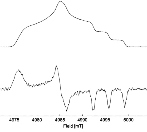
Figure 2.5. 1H polarization buildup curves of a) amorphous and b) crystalline 95% deuterated O T P ... .... ... --- 5 5 Figure 2.6. CW EPR field profiles of bTtereph at 9 GHz...56
Figure 2.7. 13C CPMAS DNP enhanced spectra of indomethacin glass...60
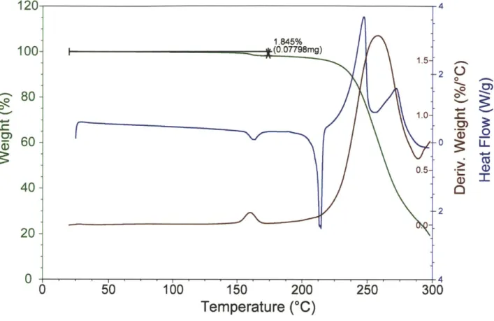
Figure 2.S1. Thermogravimetric analysis (TGA) and differential scanning calorimetry (DSC) plots of bT tereph ... 64
Figure 2.S2. NMR field dependent 1H enhancement (c) profile of bTtereph...65
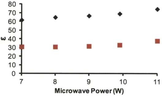
Figure 2.S3. DNP enhancement (c) as a function of gyrotron microwave power ... 66
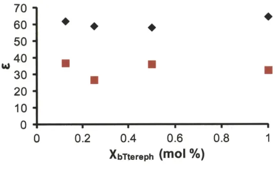
Figure 2.S4. DNP enhancement (s) as a function of bTtereph concentration ... 67
Figure 2.S5. Experimental and simulated EPR spectra of bTtereph...70
Figure 2.S6. Probablity distribution of Lorentzian linewidth used to simulate the 9 GHz EPR spectrum of bTtereph in crystalline OTP...71
Figure 2.S7. Pulsed 140 GHz EPR spectra of bTtereph in fully deuterated amorphous OTP...72
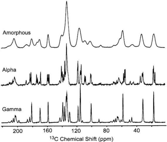
Figure 2.S8. Room-temperature 13C CPMAS NMR spectra of amorphous and crystalline (a and y crystals) indom ethacin ... 73
Figure 3.1. Figure 3.2. Figure 3.3. Figure 3.4. Figure 3.5. Figure 3.6. Figure 3.7. Figure 3.8.
13C CPMAS spectra of form I ibuprofen and cellulose-ibuprofen...83
13C CPMAS spectra of form I acetaminophen and cellulose-acetaminophen...85
Expanded 13C CPMAS spectra of acetaminophen ... 86 13 C CPMAS DNP of cellulose membrane in water and EtCl4 ... . . . . 88
13C CPMAS DNP of cellulose-acetaminophen ... 90
Static 2H NMR spectra of d3-acetaminophen at various temperatures...91
13C CPMAS spectra of form I ibuprofen and silica-ibuprofen...93
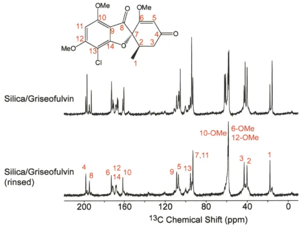
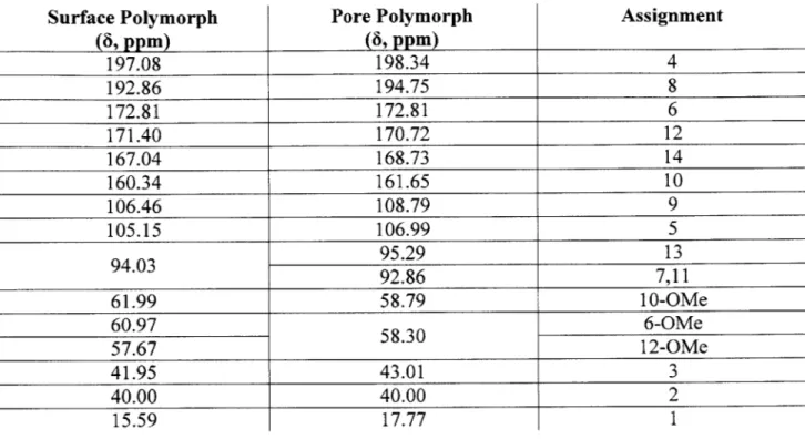
13C CPM AS spectra of silica-griseofulvin ... 94
Figure 4.1. Energy level diagram for an electron-nuclear coupled spin system...102
Figure 4.2. Experim ental schem e of TJDNP ... 106
Figure 4.3. Conceptual diagram of indirect versus direct melting in the TJDNP experiment...108
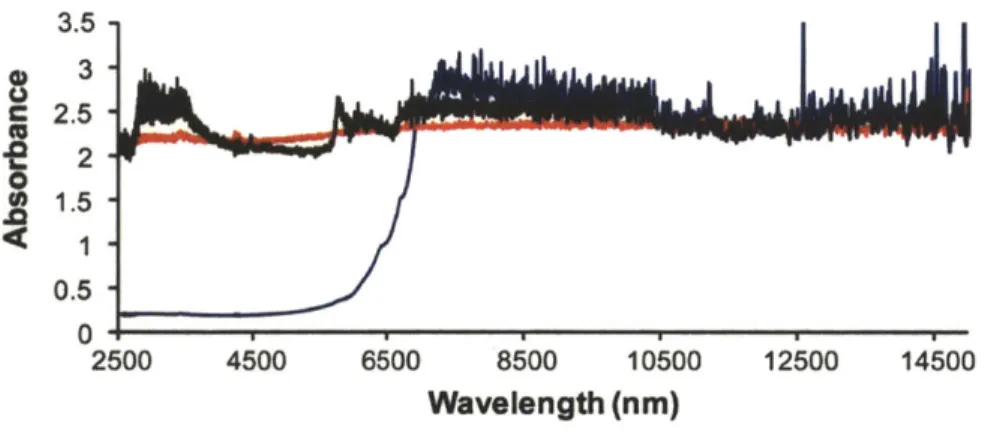
Figure 4.4. IR and NIR absorbance profile of zirconia, sapphire, and SiC ... 109
Figure 4.5. NIR absorbance of DMSO/H20 and d6-DMSO/D 20...110
Figure 4.6. The growth of liquid state proton NMR signal upon laser irradiation ... 111
Figure 4.7. The refreezing of TJDNP sample after laser irradiation ... 111
Figure 4.8. TJDNP 13C NMR spectrum of 800 mM glucose in DMSO/H20...113
Figure 4.9. Synthesis of the thermoresponsive poly(norbomenyl) polymer bearing TOTAPOL m oieties ... . . ... 116
Figure 4.10. 2pESEEM of TOTAPOL moieties in the LCST polymer...120
Figure 4.11. Solution 13 C NMR spectrum of 800 mM U-'3C glucose...121
Figure 4.12. DNP enhanced 13C NMR spectrum of 13C-urea in d6-DMSO/D20 ... 124
Figure 4.13. 13C polarization built-up curve of urea sample...125
Figure 5.1. Pake doublet pattern for 2H in solid powder sample ... 131
Figure 5.2. The quadrupolar echo sequence ... 132
Figure 5.3. Deuterium line shapes at various motional rates for D20 two-fold hop and aromatic ring flip ...---... . . ... 134
Figure 5.9. Static 2H NMR spectra of d54-DMPC and VDAC1/d54-DMPC 2D crystals...147
Figure 5.10. Perpendicular quadrupolar splitting, AvQI, as a function of temperature ... 148
Figure 5.11. Expansion of 2H NMR spectra of d 54-DMPC and VDAC 1 /d54-DMPC 2D crystals at 2 9 C ... 14 9 Figure 5.12. Static 2H NMR spectra of VDAC1/d5 4-DMPC ~1:25 protein-to-lipid ratio and ~1:50 as a function of tem perature...151
Figure 5.13. Schematic illustrations of a projection of the VDAC1 monomer and dimer ... 154
Figure 5.14. De-Paked 2H NMR spectra of d 54-DMPC and VDAC 1 /d54-DMPC 2D crystals .... 156
Figure 5.15. Protonated DPhPC and DPPC ... 158
Figure 5.16. Temperature dependent 2H spectra of d78-DPhPC and d78-DPhPC:M2...160
Figure 5.17. Static 2H NMR spectra of d78-DPhPC at 173 K and 208 K ... 161
Figure 5.18. Temperature dependent 2H spectra of d62-DPPC ... 162
Figure 5.19. Choline headgroup of DMPC and DPhPC ... 164
Figure 5.20. The Static 2H NMR spectrum of chain deuterated DPhPC at 290 K ... 164
Figure 5.21. X-ray crystal structure of Zn2(TCPE)...166
Scheme 5.1. Synthesis of H4TCPE-d16 . . . .. . . . . . . . . . .169
Figure 5.22. Temperature-dependent X-ray diffraction studies of t...174
Figure 5.23. Static 2H NMR spectra of TPE-d2 0.. . . . . 176
Figure 5.24. Static 2H NMR spectra of 1c taken between 298 and 423 K...177
Figure 5.25. Experimental and simulated quadrupolar spin-echo solid-state 2H NMR spectra of la during heating and transformation into lb and of lb during cooling...178
Figure 5.26. Arrhenius plot of the two-fold phenyl exchange rate in lb during cooling ... 179
Figure 5.27. 13C CPMAS NMR spectra of fully desolvated lH and ic ... 180
Figure 5.28. DFT-calculated structures of truncated formate-capped models of lb...181
Figure 5.29. PES for the flipping of one phenyl ring in a truncated model of lb and sum of the electron density at the C-C single bond critical points...182
Figure 5.30. PES for the flipping of one phenyl ring in a model of TPE ... 183
Figure 5.S1. Thermogravimetric analysis plots for 1 and 1H...194
Figure 5.S2. Simulated (red) and experimental (black) PXRD patterns of lc ... 195
Figure 5.S3. Variable temperature 'H NMR spectra of TPE and H4TCPE ... 196
Figure 5.S4. DFT-calculated PES for phenyl ring flipping in styrene...198
Figure 5.S5. DFT-calculated PES for phenyl ring flipping in benzoic acid...199
Figure 5.S6. DFT-calculated PES for phenyl ring flipping in vinylbenzoic acid with orthogonal ethylene and carboxylic acid groups and coplanar ethylene and carboxylic acid groups ... 200
Figure 5.S7. PXRD patterns of ic and fully desolvated lH ... 201 Figure 5.S8. Geometry-optimized conformations of TPE ... 202 Figure 5.S9. DFT-calculated molecular conformations of truncated lb model ... 203 Figure 5.S 10. DFT-calculated PES for phenyl ring flipping in terephthalic acid with coplanar ethylene and carboxylic acid groups...204 Scheme 5.S1. Depiction of the proposed desolvation process that occurs during the conversion of ib to i c ... 2 0 6
Figure 6.1. 13
C DNP enhanced CPMAS spectra of 13C-urea in glycerol/D20/H20 ... 219 Figure 6.2. 1H DNP field profiles of various bT-thio based radicals...221 Figure 6.3. bTtereph synthetic process ... 222 Figure 6.4. Chemical structures and 140 GHz EPR spectra of three narrow-line radicals: Trityl, T M T , and SA -B D PA ... 223 Figure 6.5. Direct polarization of 13C, 2H, and
170 field profiles acquired at 5 T ... 225
Figure 6.6. Direct polarization of low-gamma nuclei...227 Figure 6.7. MAS DNP sample preparation protocols for biophysical systems ... 230 Figure 6.8. Artistic rendering of the new waveguide designed for the 460 GHz / 700 MHz DNP N M R spectrom eter...233 Figure 6.9. 13C-13C DARR spectrum of U- 3C-Proline in d
8-glycerol/D20/H20 ... 234
Figure 6.10. '3C-'3C correlation spectrum of U-13
List of Tables
Table 2.1. Biphasic DNP ' H Polarization buildup time constants (rB, and rB2) and fraction (/) of
crystallized O T P ... 54
Table 3.1. T1 ('H) of form I ibuprofen and cellulose-ibuprofen...84
Table 3.2. T, ('H) of form I acetaminophen and cellulose-acetaminophen...87
Table 3.3. 13C chemical shifts of silica-griseofulvin polymorphs ... 95
Table 4.1. GPC characterization of TOTAPOL-containing polynorbornenes polymers...118
Table 4.2. 'H and 13C spin-lattice relaxation time of 800 mM 13C6 glucose in D20 containing TOTAPOL and TOTAPOL polymer at various concentrations...122
Table 4.3. 'H and 13C spin-lattice relaxation time of 800 mM glucose in D20 containing TOTAPOL or TEMPO with or without blank PEG polymer ... 123
Table 5.1. DFT-calculated low-energy vibrational modes for TPE...184
Table 5 .S 1. X-ray crystal structure refinement data for TPE-d20, 1 a and lb at various tem p eratures ... 193
Table 5.S2. The shortest Ph...Ph contacts, the dihedral angles and the ethylene twist angles in the determined crystal structures at 93, 298, and 373 K using the indices specified in the sample TPE stru ctu re ... 19 7 Table 5.S3. Activation energies, C=C bond lengths, and selected angles for geometry-optimized conformations of TPE at fixed CA-CAr-C=C dihedral angles ... 202
Table 5.S4. Dihedral angles for geometry-optimized conformations of TPE at fixed CAr-CAr-C = C dihedral angles...202
Table 5.S5. Activation energies, C=C bond lengths, and selected angles for geometry-optimized molecular conformations of a truncated model of lb at fixed CAM-CAM-C=C (1250, 50, and 950) d ihedral an g les ... 2 03 Table 5.S6. Dihedral angles for geometry-optimized molecular conformations of a truncated model of lb at fixed CA,-CA--C=C (125', 5', and 950) dihedral angles...203
Table 5.S7. Electron density (e- A-3) at bond critical points for selected bonds along PES for ring flipping in truncated m odel of lb...205
Table 6.1. Physical properties for selected biologically relevant NMR nuclei ... 224
Chapter 1: Introduction to Solid-State NMR and
Dynamic Nuclear Polarization
Since its discovery by Purcell et al.,' nuclear magnetic resonance (NMR) has grown to become an indispensible analytical method in a variety of scientific disciplines, notably in synthetic chemistry, biochemistry, structural biology, and materials science. In this chapter, an introductory background on NMR is provided to give the gentle readers a good basis to understand the subsequent chapters of this thesis. We will examine the relevant nuclear spin interactions that take place in NMR, describe common pulse experiments, and give a brief introduction on dynamic nuclear polarization (DNP), which is an exciting method that can improve NMR signal-to-noise by 2 to 3 orders of magnitude. For a more detailed treatment on NMR, the books by Charles P. Slichter,2 Melinda J. Duer,3 and Malcolm H. Levitt4 are useful texts for references.
1.1. The Spin Interactions
The full Hamiltonian on a nuclear spin residing inside an NMR magnet, no radio frequency pulse yet, can be written as follow:
A A A A A A
H=HZ+ HCH+ H H J+ Q+ (1)
A
Hz is called the Zeeman interaction, experienced by the nuclear spin because it is under the
external magnetic field exerted by the NMR magnet. The rest of the terms are called internal
A
A A A
interaction, HD is the dipolar interaction, Hi is the scalar interaction, and HQ is the quadrupolar
interactions. This section examines each interaction and briefly describes their importance.
1.1.1. The Zeeman Interaction
The Zeeman interaction experienced by a nuclear spin is given by
A A A
H = -yh Iz Bo = -cooh Iz (2)
where Bo is the strength of the applied external magnetic field, y is the nuclear gyromagnetic
A
ratio, and Iz is the spin angular momentum operator. By convention, the applied magnetic field is along the z axis, hence the z designation. It is common to see Eq. (2) written in terms of the Larmor frequency, oo. Physically, the Larmor frequency describes the nuclear spin precession about the applied magnetic field. NMR spectroscopists typically use the 'H Larmor frequency to describe NMR field strengths as opposed to actually using Bo. Therefore, a "211 MHz NMR spectrometer" has a magnet with a field strength of approximately 5 T.
The eigenvalues of the Zeeman Hamiltonian can be written as
H II, m) = E,,,, I I, m) (3)
where Ei,m is the energy of eigenstate
|I,
m). Substituting Eq. (2) into Eq. (3), we getA A
H I I, m) = -yhBom I, m) (6)
And therefore the energies of the eigenstates are
EI, = -yhBom (7)
I is the quantum number describing the total angular momentum, and m is referred to as the azimuthal quantum number that can take any value from -I, -1+1...+1 for a total of 21+1 possible numbers. For many of the common NMR active nuclei (e.g., 'H, C, 1N 31P etc.), I = 2, so
therefore m = ±2. For these nuclei, Eq. (7) is thus simplified into
E, 1= - hBO (8)
2
And the difference between the two energy levels is
AE = yhBO = wooh (9)
Eq. (9) gives us the energy level diagram shown in Figure 1.1. As the magnetic field strength increases, the energy gap between the levels widens, leading to a greater Boltzmann population difference. At temperature equilibrium, the Boltzmann distribution for each eigenstate is given by
exp
exp=V 5 -
'
(10)-Ex Ev
exp ''(11) ''~1
We can obtain the Boltzmann polarization as
P yhBO (12)
2kT
From this equation, we can see that nuclear polarization is proportional to BO, and inversely proportional to temperature. This finding motivates the development of higher field magnets and cryogenic temperature systems for NMR experiments. Assuming a 10 T magnet at room temperature (298 K), we find that P is only 5.5x10⁻⁶ for 'H (y = 42.6 MHz/T) and 1.4x10⁻⁶ for
3C (y = 10.7 MHz/T). This calculation, coupled with the fact that many NMR active nuclei are
low in natural abundance (e.g., 13C 1.1%. 15N, 0.4%), means that NMR is inherently an
insensitive analytical method. For biological solids, isotopic labeling is commonly employed to increase NMR signal-to-noise and save acquisition time.
E
0
1.1.2. The Chemical Shift Interaction
If Zeeman interaction is the only term experienced by the nuclear spins, then each NMR active nuclear isotope would have only one single NMR peak in a homogeneous magnetic field, corresponding to its Larmor frequency as shown in Eq. (9). Evidently, this is not true. The nuclear spins are surrounded by electrons, which are also magnetic and therefore induces a secondary magnetic field that perturbs the external magnetic field felt by the nuclear spins. The introduction of this inhomogeneity is called the chemical shift interaction, with the Hamiltonian
A A
Hcs = *I-c--BO (13)
where c is the chemical shielding tensor. In NMR experiments, the absolute Larmor frequencies (Zeeman plus chemical shift) are not reported directly because the chemical shift contribution is only on the order of ppm compared to the Zeeman interaction. Instead, the chemical shift is reported as an offset from a reference frequency. Common reference samples include tetramethylsilane for solution NMR and adamantane for solids. Assuming the chemical shift tensor is symmetric, the definition of chemical shift is
9 = 9i + IAs (3 cos2 0 1) (14)
2
= Vref (15)
Vref
where 6iso is called the isotropic chemical shift and Acs called the chemical shift anisotropy. The isotropic chemical shift is the most useful information provided by NMR, allowing one to obtain localized molecular information. Any undergraduate organic chemistry textbook is likely to contain a table of NMR chemical shifts and their corresponding functional groups.
From Eq. (14), we can see that the anisotropic part of the chemical shift interaction is angular dependent. In other words, it depends on the orientation of the chemical shift tensor with respect to the external magnetic field. In solution NMR, fast molecular tumbling eliminates any orientation dependence, and therefore averages the anisotropic portion of the chemical shift to zero, leaving only the 6iso for observation. In solid-state NMR of a static sample, both components are present and produce a "powder pattern" that includes contributions from all possible molecular orientations. The powder pattern can be hundreds of ppm wide, and for most circumstances it is not useful. Magic angle spinning (MAS) is applied to address this concern. If we spin a solid sample at an angle OR away from the external magnetic field, then the angle describing tensor orientation becomes time dependent, and the average is
(3cos2 0-1 = 1(3cos2 OR _)(3cos2 8J-) (16)
where
f
is the angle between the spinning axis and the tensor principal z-axis. By setting OR to54.740, we find that 3cos 2OR- 0. This angle is therefore called the "magic angle". By spinning at this angle at sufficient frequency (a factor of 3 to 4 greater than Acs), we can adequately minimize chemical shift anisotropy so only the 6isO is observed for solid samples. Spinning at a lower frequency only partially averages the powder pattern and produces "spinning sidebands" that collectively trace the shape of chemical shift anisotropy and are each separated by the MAS frequency.
AI (Ir)(S-r)
Hi -(2= L7,2sh S -3
4zr r 3 r5 (17)
for two spins with designation I and S. The above equation is commonly expressed in spherical polar coordinates, so it takes the form
HD= 47r r17s[A+B+C+D+E+F]
(4r ) r
(18)
where
A=JzSz(3cos2_1
B = I.S-+S _+](3cos2
oi)
C = ++ z+ z
j
sin 0 cos e3 [A D =I
2
A A A s
zS_ +1I_ Sz
]
sin0
cosO
3 [= 2 -2 E =-41+ 8+ ]sin2 Oe2' 3A F= -4L
U-
]
sin 2 Oe +2 +The dipolar interaction between nuclei of the same isotope is called homonuclear dipolar coupling (e.g., 'H-H, 13C- C, etc.), and between nuclei of different isotopes is called
As we can see from Eq. (18), the dipolar interaction is orientation dependent. In solution NMR where there is fast molecular tumbling, the dipolar interaction averages to zero. In solid-state NMR, dipolar coupling can be on the order of tens of kHz. In a homonuclear system, the raising and lowering operators of the dipolar Hamiltonian (the "flip-flop" terms present in the B term) interfere with MAS averaging and causes homogeneous broadening of resonance lines. This is the reason why MAS experiments of 1H still result in lines that are tens of kHz wide unless the sample is heavily deuterated to minimize 1H-1H coupling or the frequency of spinning is very fast (up to 100 kHz). The same effect is observed for MAS experiments of 13C, since for most samples the 13C is dipolar coupled to a network of coupled 'H, and consequently MAS only leads to an incomplete averaging of the 1H-13C dipolar coupling.
In order to address the issue of dipolar line broadening, decoupling experiments are commonly employed to improve NMR spectral resolution. Decoupling works by applying a high-power multiple pulse sequence to irradiate target nuclei. Application of RF irradiation perturbs the spin Hamiltonian, and the goal is to obtain an averaged Hamiltonian where the dipolar coupling is zero. Conceptually, the effect of decoupling RF rapidly causes the nuclear spins to undergo repeated transitions (a <-.
f)
at a rate larger than the strength of dipolar coupling, and therefore the time-averaged dipolar coupling becomes zero. Homonuclear decoupling experiments, in which the decoupling targeted nuclei is the same isotope as the observed nuclei, include WAHUHA5 (allegedly6 named after its inventors Waugh, Huber, and Haeberlen) andMREV-8.7
Although in many circumstances the presence of dipolar coupling is problematic, there are situations where it is experimentally useful. Dipolar coupling is distance dependent (i.e., 1/r3). Therefore, we can utilize it to determine the distance between two nuclei and use the information to determine molecular structures. Much like the J-coupling based correlation spectroscopy (COSY) of solution NMR, the dipolar coupling can be utilized in similar ways by solid-state NMR. However, MAS reduces dipolar coupling, so the interaction needs to be re-introduced. This is accomplished by the recoupling experiments. The recoupling experiments work by applying RF pulses that are synchronized with the MAS rotor period ("rotor synchronization") in order to interfere with the MAS effect. Notable recoupling experiments include the rotational-echo double-resonance (REDOR),'0 the transferred-echo double-resonance (TEDOR),"-" and the radio-frequency driven recoupling (RFDR).13
1.1.4. The Scalar Interaction
The scalar interaction, commonly referred to as the J-coupling, is similar to the dipolar interaction, but requires mediation through the electrons in chemical bonds. Therefore, it is also called the indirect dipolar coupling. The effect of J-coupling is not large, only on the order of tens of Hz, but useful as it permits mapping of chemical bonds within molecules. In solution NMR, due to the absence of the direct dipolar coupling, J-coupling is apparent as peak splitting and forms the basis for COSY. However, in solid-state NMR, the various line broadening effects (e.g. residual dipolar coupling, higher order interaction terms, solid disorders, etc.) generally overshadow the effect of J-coupling. Therefore, J-coupling only receives little attention in solid-state NMR. Nevertheless, with the advent of very fast MAS (> 65 kHz) that further improves resolution, it may soon become viable to utilize J-coupling in the solid-state experiments.1
1.1.5. The Quadrupolar Interaction
Nuclear spins with I > 1 (e.g., 2H, '4N, 170, etc.) have nuclear electric quadrupole moments that interact with the electric field gradient at the nuclei. This is called the quadrupolar interaction, which has the following Hamiltonian
A eQ A A
HQ = I.lvel (19)
21(21 -
l)h
where e is the proton charge, V is the electric field gradient tensor, and
Q
is the nuclear quadrupole moment. The dot product in Eq. (19) can be fully expanded intoA A A A A A A A
I.v.I=IxvxxIx+x vx I,+Ix V, IZ+...
As we can see Eq. (19) becomes quite messy. Therefore, secular approximation is commonly used to remove the excess terms when the quadrupolar interaction is considerably smaller than the Zeeman interaction. To do this, we break the full Hamiltonian into ordered terms,
A Full A (1) A (2)
HQ =Ho + H +... (20)
A (1) A (2)
where HQ is the first-order quadrupolar Hamiltonian, HQ is the second-order Hamiltonian, and so on. For nuclei with relatively small quadrupolar interactions, notably 2H, on the order up
to hundreds of kHz, only the first-order term needs to be considered. Conversely, for half-integer nuclei with larger quadrupolar interactions such as 170 and "Cl, which can have quadrupolar
1.2. Common Solid-State NMR Experiments
In this section, we give an introduction to the most common pulsed solid-state NMR experiments. Starting with the single pulse sequence, or Bloch decay, which is the simplest experiment.
1.2.1. The Single Pulse Experiment
900
Figure 1.2. The single pulse experiment followed by detection of FID.
The single pulse experiment is the simplest NMR pulse sequence, consists of a single radio frequency (RF) pulse followed by detection of free induction decay (FID), as shown in Figure 1.2. The RF pulse introduces an oscillating magnetic field that is time dependent and perpendicular to the BO field. Combined with Zeeman interaction, the laboratory frame Hamiltonian in the presence of an RF pulse becomes
A (A
H =-7h BI z+B, cos(oft)I) (21)
for an RF field that is oscillating along the x axis. B1 is the magnitude of the RF field and of is the frequency of the radio pulse. The oscillating B1 field can be considered as two counter-rotating fields; the resonant component that rotates in the same direction as the Larmor frequency
and the off-resonant component that goes against the Larmor frequency. Only the resonant component has a major effect on the spin system, so Eq. (21) can be rewritten as
H =-Yh Bo0Iz+Be 'rft Ixerz (22)
To simplify, we can utilize a rotating frame that is rotating about Bo at frequency Orf, so B appears static. The rotating Hamiltonian then becomes
H'
= hir(Bo
-Wff)I+Z± 7B, Ix (23)Applying this Hamiltonian into the time-dependent Schr6dinger equation, we get
h aT'A A
-. =-h (yBO - ,o )z+ YB Ix )' (24)
which has eigenfunctions
V'= Ca (t)|Ia)+ c (t)Lp) (25)
From Eq. (25), we can see that the eigenstates of the RF perturbed Hamiltonian is a linear combination of the Zeeman eigenstates. In other words, the RF field mixes the Zeeman states. This process is called excitation.
called transverse magnetization, which induces an oscillating current in the NMR coil that is then recorded as the FID. The flip angle of magnetization away from the z axis is defined as
0, = YBrf (26)
In other words, it is the angle turned by B1 in time Trf, and the term yB1 is commonly called the nutation frequency. When Orf is 900, as denoted in Figure 1.2, the magnetization is perfectly flipped to the xy plane, thereby maximizing transverse magnetization and the NMR signal. The RF pulse can be applied along the x axis or the y axis, this is called the phase of the pulse. Four phases (x, y, -x, -y) are possible for a single RF pulse.
After the RF pulse, the transverse relaxation slowly decays following the equations
MX = M,, sin
(cot)exp
Tj
M, = Meq cos
(aOt)exp
T (27)2
where T2 is called the transverse relaxation time constant. Meanwhile, the longitudinal
magnetization is slowly rebuilt along the z axis back to Boltzmann equilibrium following the equation
M, = Meq 1 - exp (28)
where T, is commonly called the spin-lattice relaxation time constant. Measurements of T, and T2 can be very informative as both parameters are dependent on molecular motion and they may
by the inversion-recovery sequence' or, in cases of long TI, the saturation recovery sequence.17 T2 can be measured by the spin echo sequence.18
1.2.2. The Cross Polarization Experiment
90X
(CP)-ydecoupling
130
r"C
(P)..yAA
Figure 1.3. The cross polarization experiment from 1H to 13C.
While the single pulse experiment described in the previous section can be performed for all NMR active nuclei, the cross polarization experiment (CP)'9 is commonly used to detect low natural abundance nuclei (e.g., 13C or 15N) when they are coupled to 'H. Low natural abundance
nuclei very often have long T, due to the absence of strong homonuclear dipolar coupling, meaning that the magnetization recovery after each experiment is slow and thus it can take a long time to properly signal average. Therefore, instead of detecting directly on the low natural abundance nuclei via single pulse, the CP experiment aims to transfer polarization from the abundant nuclei (usually 1H) to the surrounding low abundant nuclei. Doing so leads to an
As shown in Figure 1.3, the CP experiment is initialized with an excitation pulse on 'H to generate 'H transverse magnetization. In the figure, a 900 x pulse is used, so the transverse magnetization is along the -y direction. Following the excitation pulse, a contact pulse is applied along the -y axis on both nuclei, 'H and 13C. This generates a spin-lock field that can be designated B1('H) and B1( 3C). Cross polarization from 'H to 13C occurs when the Hartmann-Hahn matching condition,2 0
YHB, ( H)= (BI( 13C) (29)
is satisfied. At the Hartmann-Hahn condition, the energies of the 'H spin states and the 13C spin
states are the same, therefore the larger 'H polarization is transferred to 1C through the heteronuclear dipolar interaction without net energy change of the whole system. Following CP, we can then detect the cross polarized 13C signal while applying decoupling pulses on 'H. The
experiment can be repeated again after 'H longitudinal magnetization rebuilds, which is dependent on the shorter 'H T, as opposed to the longer 13C T1. Typically, for 13C that are strongly coupled to many 'H, such as methyl and methylene, the CP contact time required is short. Likewise, for 1C that are relatively farther from other 1H, such as carbonyl, a longer CP
time is often needed. For organic solids, a contact time of 1-3 ms is usually sufficient. Precise optimization of CP time is system dependent.
In MAS experiment, dipolar coupling is attenuated. Therefore, at higher MAS frequency CP loses transfer efficiency and longer contact time is sometimes needed. MAS also introduces time dependence to the dipolar interaction Hamiltonian, which can be compensated by varying, or ramping, the RF amplitude of the contact pulse. Figure 1.3 shows a ramped contact pulse on
1.2.3. The Hahn Echo Experiment
900x
180*y
Figure 1.4. The Hahn echo sequence.
Spectra with broad linewidths have rapidly decaying FIDs. The full-width-half-height (FWHF) of a given NMR peak is 1/T 2*, where T2* is the effective transverse relaxation time
constant accounting for both homogeneous and inhomogeneous broadenings. Shorter T2*
therefore means broader NMR resonances. In these situations, immediately recording the FID after the last pulse, such as in the single pulse or the cross-polarization experiment, might not be suitable due to the required dead time after the last pulse. The dead time is the delay between the last NMR pulse on the observed channel and the actual beginning recording time of the FID, and it is usually between 10-20 ps. This delay is needed because immediately after the application of a pulse, the NMR coil experiences "ringing" that are large oscillatory signals that often overshadow the FID and therefore introduce significant spectral distortion. They might also harm the spectrometer receiver by oversaturating it. For most experiments, the 10 ps dead time does not pose a significant problem because the FID is sufficiently long and thus not much signal intensity is lost. However, for spectra with broad linewidth and short FID, most notably
The echo sequence works by refocusing the FID away from the last NMR pulse, and therefore recording the FID is no longer constrained by the spectrometer dead time. For spectra broadened by heterogeneous interaction such as the chemical shift anisotropy or the heteronuclear dipolar coupling, the Hahn echo can be used. For spectra broadened by the quadrupolar interaction or the homonuclear dipolar coupling, the solid echo, commonly refers to as the quadrupolar echo (90x*-t-90y*-r) is used instead. Using the Hahn echo as an example
since it is easily visualized, the vector diagram for echo refocusing is shown in Figure 1.5. Choosing the appropriate T for maximum echo intensity is dependent on T2 (not the same as T2*,
T2 only depends on the homogeneous broadening), and a t array can be set up to measure T2
precisely. In practice, it is typically advisable to make the second r slightly shorter than the first -to allow recording -to begin before the -top of the echo, and then left shift the time domain prior -to Fourier transforming the spectrum. Doing so accounts for the effect of finite pulse width and any spectrometer hidden delays.
a)
b)
C)d)
,
y
_. _y
-
..
y
y
Figure 1.5. Transverse magnetization refocuses during the Hahn echo sequence, a) the transverse magnetization is along the -y axis after the first 90x pulse, b) the magnetization dephases from inhomogeneous interactions after a period t, c) the 180y pulse flips the magnetization as shown
by the green arrow and allows refocusing to begin, and d) the magnetization is refocused along the -y axis after a second period -.
1.3. Introduction to Dynamic Nuclear Polarization
In our discussion of the Zeeman interaction, it was noted that NMR is an intrinsically insensitive technique due to the small Boltzmann polarization generated in Eq. (12). In order to obtain satisfactory signal to noise, an NMR experiment may need to signal average for hours or even days. Improving the NMR signal to noise and thereby reducing the necessary acquisition time is therefore a central part of NMR hardware development. To improve the signal, one can optimize the obtainable Boltzmann polarization from Eq. (12). This strategy has led to the development of high field NMR magnets over the past several decades. Currently, the highest field commercial NMR spectrometer available from Bruker is the Avance 1000, boasting a 23.5 T magnet that is a factor of 2 greater than the more conventional 500 MHz spectrometers (11.7 T). In addition to better sensitivity, high field NMR also provides improved resolution if chemical shift anisotropy can be sufficiently reduced by MAS. Given that the chemical shift interaction increases with the magnetic field as shown in Eq. (13), the development of high field NMR magnets has been concurrent with improving MAS probes to allow ever faster MAS frequencies. Lastly, high field NMR is advantageous for studies involving quadrupolar nuclei, as the second-order quadrupolar coupling is inversely proportional to the magnetic field.
Other than increasing the magnetic field, better Boltzmann polarization can be achieved by acquiring the NMR data at cryogenic temperatures. If the sample can be cooled to nearly liquid nitrogen temperature (80 K), the signal enhancement from the reduced temperature is a
made to the spectrometer electronic components and designs have led to a reduction of noise for the NMR experiment.
While the hardware improvements described above have significantly improved NMR signal to noise, dynamic nuclear polarization (DNP) has been shown to provide even greater NMR signal enhancement. At its very essence, DNP aims to cross-polarize nuclear polarization using paramagnetic electron polarization that is the basis of electron paramagnetic resonance (EPR). Since the Zeeman interaction of electrons is much greater than that of nuclei (~660 times larger compared to 1H, and more for lower y nuclei), the potential non-Boltzmann polarization that can be generated is significant. DNP was first proposed by Overhauser in 1953, and followed by the experimental verification by Carver and Slichter.25 However, as NMR pursued higher fields beyond 5 T, there was no microwave source with the appropriate frequency (> 140 GHz) and power (> 10 W) that could adequately saturate the EPR transitions necessary to carry out DNP efficiently. Consequently, despite its early discovery, DNP was thought to only have limited applications and was not widely adopted. In the 1990s, Griffin and co-workers revived DNP as a solid-state NMR technique with the introduction of frequency (> 140 GHz), high-power (> 10 W) gyrotrons.26 The introduction of gyrotrons, coupled with the development of suitable paramagnetic polarization agents,27 has allowed DNP to achieve NMR signal enhancements upward of two to three orders of magnitude that translates to significant reduction of experimental acquisition time.
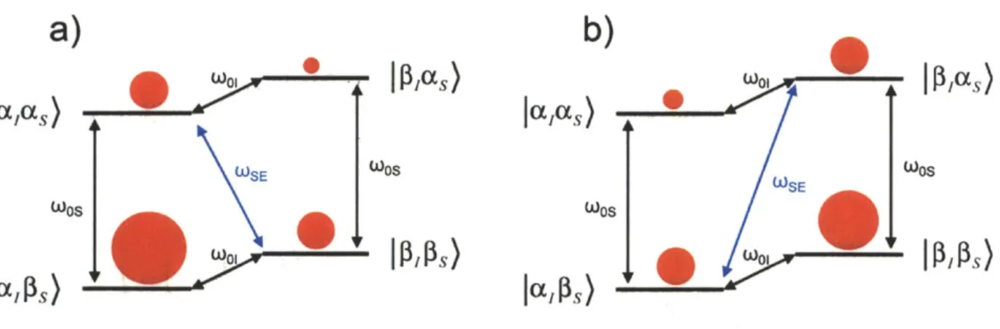
To understand how DNP functions, we examine briefly here the three common solid-state DNP mechanisms, the solid effect (SE),28-30 the cross effect (CE),31-35 and the thermal mixing (TM).36-39 The SE is a two-spin process that is the simplest of DNP mechanisms. It is the dominant DNP mechanism when the condition oo, > 6, A is matched, where CoOl is the nuclear
Larmor frequency, 6 is the homogeneous EPR linewidth, and A is the inhomogeneous EPR linewidth. To visualize the SE, we first consider a two-spin system where a nucleus is coupled to an electron under an external magnetic field, as shown in Figure 1.6. The Hamiltonian for this two-spin system in the rotating frame can be written as4 0
H Os s = S -co 1o I + ASJ + BSJ,, (30)
where oos is the electron Larmor frequency of the EPR transition, oo, is the nuclear Larmor frequency of the NMR transition, and A and B are the secular and nonsecular hyperfine interaction. If the hyperfine interaction were absent in this two-spin system, the cross transitions would be forbidden. However, the nonsecular hyperfine interaction allows the mixing of states to occur between the
|al
as) and 1p8 as) states, and also the|a8
)
and 1,ps) states. This mixing of states makes the cross transitions /3pcas) to apIs) and Ja~as) to /3pps) allowable. When microwave is applied at these cross transition frequencies, O)MW = s ±coo± , , with sufficientpower to saturate the transitions, the electron and the nucleus spin states undergo a "flip-flop" and effectively transfer the electron polarization to the nuclear polarization, as shown in Figure 1.7. Saturating the
|p8as)
to japis) transition generates net negative non-Boltzmannpolarization, while saturating the laas) to 1,s) transition has the opposite effect. The non-Boltzmann polarization from SE (or the other DNP mechanisms) can be quite substantial. Theoretically, the maximum achievable enhancement is the ratio 7s/71, which is 660 for 'H and
ccxc
0aP)s
I
S)
I S)
l
l OS
OS
W0I
S)
Figure 1.6. A electron-nucleus coupled two-spin system under an external magnetic field. The red dots conceptually show the relative spin population at each spin state but are not to scale. The two oos show the electron Larmor frequency of the EPR transitions, and the coo show the nuclear Larmor frequency of the NMR transitions. Due to the difference in gyromagnetic ratio, the electron polarization (shown conceptually as the difference in sphere sizes) is far larger than the nuclear polarization.
a)
b)
0 W01
PlI~as)W0
as
lalas) laas) WSE S SE WOS S OSSIa
@s)
W
laPs)
Figure 1.7. The solid effect after application of microwave at two matching frequencies, a) the
I
acas) toj1,8ps)
transition is saturated and generates net positive non-Boltzmann polarization, and b) the /,as) 1 tojaps)
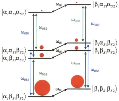
transition is saturated instead and generates net negativeWhen the condition 8 < ooj < A is matched, the CE becomes the dominant DNP mechanism. While the SE only involves one electron and one nucleus, the CE is a three-spin process involving two electrons and one nucleus, as shown in Figure 1.8. In this system, the state
jalas1s2) and /,p1/SIaS2) are close in energy, and through manipulation of electron-electron
and electron-nuclear dipolar couplings by careful polarization agent design, the two states can be optimized to be nearly degenerate, matching the condition
0 si -wOs 21 * (31)
If this degenerate matching condition is satisfied, when microwaves are applied along the first or the second electron transition, an energy conserving "flip-flip-flop" process can saturate both the lalaS1Ps2) and the /,p1/sias 2) state, leading to substantial non-Boltzmann polarization along the
NMR transitions as shown in Figure 1.9.
In practice, the CE generally produces larger polarization enhancement compared to the SE,41 and therefore it is often the favored DNP mechanism. In recent years, it was found that utilizing organic biradicals as polarization agents for CE is considerably more efficient at satisfying the match condition specified in Eq. (31) compared to using monoradicals at higher concentration.4 2 Optimizing the biradicals used for CE is therefore a central part of DNP research
and development. Some notable biradicals that have been successful CE polarization agents include TOTAPOL,2' bTbK,43 bTbtk-py,44 TEKPol,45 and AMUPol.46 The efficacy of biradicals
W P2 XSIS2)
lI cc
aI
1aS
2)
Ln*OW
1 2 OOS2 WOS1 WOS2 WOS1 W0 1 PIASIPLS 2) I SPS2 0 P SOS2 Ia S1aS2)AI* r; WOS2 WOS1 WOS2 WOS1 F1 lo ,W01 IPS IPS2)Figure 1.8. A three-spin coupled system involving two electrons and one nucleus, marking all the allowable nuclear and electron transitions.
a)
W0 P/aS[(S2) i SlOS2 0OS1 WCE P)aSI3S2) I rX~aSjS2) ... o,3E 52) S0 IFSSSS2) WOS1 WOS1 CEI SI S2 I SI S2)b)
alas1aS2) A OOS2 WOS2 WCE (X (SIOS2 ... I a fP S 1 S2) 2 A W WI0S2 I ISIPS2 +Figure 1.9. The cross effect utilized a "flip-flip-flop" transition between two degenerate states, leading to either a) positive, or b) negative nuclear polarization enhancement depending on which electron transition (coosi or OOS2) is saturated.
PISI(S2
PCSI PS2) Of PSI S2)
IP SIPS2) J(XISIPS2
When the paramagnetic electron concentration is large and the condition col < 6, A is reached, the TM mechanism dominates. The TM is mechanistically similar to the CE. The large electron concentration creates a strongly coupled electron system, leading to a manifold of energy states that can undergo energy conserving population transfer between many degenerate states. In that regard, the TM only differs from the CE by the number of electrons involved in the process. The high number of electrons required for TM may lead to significant paramagnetic broadening of the NMR spectra, resulting in a loss of spectral resolution.
1.4. Thesis Outline
Chapter 2 compares the effectiveness of solvent-free DNP of ortho-terphenyl in its amorphous versus its crystalline state. Currently, most DNP experiments prepare the sample in a glass-forming solvent matrix such as glycerol/water or DMSO/water that may not be appropriate for all applications, notably the study of pharmaceutical solids where polymorphic properties must be preserved. A DNP approach that does not rely on a solvent matrix would make the technique more adoptable for pharmaceutical solid-state NMR.
Chapter 3 presents the solid-state NMR study of nanocrystalline pharmaceutical embedded in porous biocompatible excipients, and includes preliminary DNP results that outline the challenges of pharmaceutical DNP.
of NMR rotor material, laser wavelength, and synthesis of temperature sensitive polymer polarization agent.
Chapter 5 presents deuterium NMR results on a variety of systems including phospholipids and metal-organic frameworks. Deuterium NMR is a sensitive probe for studying molecular dynamics. A new single-channel probe was constructed to study temperature dependent 2H NMR from 150 to -173 'C. This chapter examines the phase transition of
phospholipids in the presence of membrane protein, and in a separate section examines the local dynamic within a metal-organic framework.
Chapter 6 highlights exciting high field DNP development currently ongoing in the Griffin group, including the new 700 MHz/460 GHz DNP spectrometer, radical polarization agent development, alternative sample preparation methods, and direct polarization of low-y nuclei using narrow line radicals.
1.5. References
1. Purcell, E. M.; Torrey, H. C.; Pound, R. V., Phys. Rev. 1946, 69 (1-2), 37-3 8.
2. Slichter, C. P., Principles of magnetic resonance. 3rd enl. and updated ed.; Springer: Berlin ; New York, 1996; p xi, 655 p.
3. Duer, M. J., Introduction to solid-state NMR spectroscopy. Blackwell: Oxford, UK; Malden, MA, 2004; p xiv, 349 p.
4. Levitt, M. H., Spin dynamics : basics of nuclear magnetic resonance. 2nd ed.; John Wiley & Sons: Chichester, England ; Hoboken, NJ, 2008; p xxv, 714 p., 7 p. of plates.
5. Waugh, J. S.; Huber, L. M.; Haeberle.U, Phys. Rev. Lett. 1968, 20 (5), 180-182.
6. Laszlo, P., NMR of newly accessible nuclei. Academic Press: New York, 1983.
7. Rhim, W. K.; Elleman, D. D.; Vaughan, R. W., J. Chem. Phys. 1973, 59 (7), 3740-3749. 8. Bennett, A. E.; Rienstra, C. M.; Auger, M.; Lakshmi, K. V.; Griffin, R. G., J. Chem. Phys. 1995, 103 (16), 6951-6958.
9. Detken, A.; Hardy, E. H.; Ernst, M.; Meier, B. H., Chem. Phys. Lett. 2002, 356 (3-4), 298-304.
10. Gullion, T.; Schaefer, J., J. Magn. Reson. 1989, 81 (1), 196-200.
11. Hing, A. W.; Vega, S.; Schaefer, J., J. Magn. Reson. Ser. A 1993, 103 (2), 151-162.
13. Sodickson, D. K.; Levitt, M. H.; Vega, S.; Griffin, R. G., J. Chem. Phys. 1993, 98 (9), 6742-6748.
14. Massiot, D.; Fayon, F.; Deschamps, M.; Cadars, S.; Florian, P.; Montouillout, V.; Pellerin, N.; Hiet, J.; Rakhmatullin, A.; Bessada, C., Cr Chim 2010, 13 (1-2), 117-129.
15. Torchia, D. A.; Szabo, A., J Magn. Reson. 1982, 49 (1), 107-121.
16. Vold, R. L.; Waugh, J. S.; Klein, M. P.; Phelps, D. E., J Chem. Phys. 1968, 48 (8), 383 1-3832.
17. Freeman, R.; Hill, H. D. W., J. Chem. Phys. 1971, 54 (8), 3367-&. 18. Hahn, E. L., Phys. Rev. 1950, 80 (4), 580-594.
19. Pines, A.; Gibby, M. G.; Waugh, J. S., J Chem. Phys. 1973, 59 (2), 569-590. 20. Hartmann, S. R.; Hahn, E. L., Phys. Rev. 1962, 128 (5), 2042-&.
21. Metz, G.; Wu, X. L.; Smith, S. 0., J Magn. Reson. Ser. A 1994, 110 (2), 219-227. 22. Mansfield, P., Phys. Rev. 1965, 137 (3A), A961-A974.
23. Maly, T.; Debelouchina, G. T.; Bajaj, V. S.; Hu, K. N.; Joo, C. G.; Mak-Jurkauskas, M. L.; Sirigiri, J. R.; van der Wel, P. C. A.; Herzfeld, J.; Temkin, R. J.; et al., J. Chem. Phys. 2008,
128 (5).
24. Overhauser, A. W., Phys. Rev. 1953, 92 (2), 411-415.
25. Carver, T. R.; Slichter, C. P., Phys. Rev. 1956, 102 (4), 975-980.
26. Becerra, L. R.; Gerfen, G. J.; Temkin, R. J.; Singel, D. J.; Griffin, R. G., Phys. Rev. Lett. 1993, 71 (21), 3561-3564.
27. Song, C. S.; Hu, K. N.; Joo, C. G.; Swager, T. M.; Griffin, R. G., J Am. Chem. Soc. 2006,
128 (35), 11385-11390.
28. Abragam, A.; Proctor, W. G., Cr HebdAcadSci 1958, 246 (15), 2253-2256. 29. Jeffries, C. D., Phys. Rev. 1957, 106 (1), 164-165.
30. Jeffries, C. D., Phys. Rev. 1960, 117 (4), 1056-1069.
31. Kessenikh, A. V.; Lushchikov, V. I.; Manenkov, A. A.; Taran, Y. V., Sov Phys-Sol State 1963, 5 (2), 321-329.
32. Kessenikh, A. V.; Manenkov, A. A.; Pyatnitskii, G. I., Sov Phys-Sol State 1964, 6 (3), 641-643.
33. Hwang, C. F.; Hill, D. A., Phys. Rev. Lett. 1967, 18 (4), 110-&. 34. Hwang, C. F.; Hill, D. A., Phys. Rev. Lett. 1967, 19 (18), 1011-&.
35. Wollan, D. S., Phys Rev B 1976, 13 (9), 3671-3685.
36. Wind, R. A.; Duijvestijn, M. J.; Vanderlugt, C.; Manenschijn, A.; Vriend, J., Prog Nucl
Mag Res Sp 1985, 17, 33-67.
37. Goldman, M., Spin temperature and nuclear magnetic resonance in solids. Clarendon Press: Oxford,, 1970; p ix, 246 p.
38. Duijvestijn, M. J.; Wind, R. A.; Smidt, J., Physica B & C 1986, 138 (1-2), 147-170. 39. Wenckebach, W. T.; Swanenburg, T. J. B.; Poulis, N. J., Physics Reports 1974, 14 (5), 181-255.
44. Kiesewetter, M. K.; Corzilius, B.; Smith, A. A.; Griffin, R. G.; Swager, T. M., J Am.
Chem. Soc. 2012, 134 (10), 4537-4540.
45. Zagdoun, A.; Casano, G.; Ouari, 0.; Schwarzwalder, M.; Rossini, A. J.; Aussenac, F.; Yulikov, M.; Jeschke, G.; Copdret, C.; Lesage, A.; et al., J. Am. Chem. Soc. 2013, 135 (34),
12790-12797.
46. Sauvee, C.; Rosay, M.; Casano, G.; Aussenac, F.; Weber, R. T.; Ouari, 0.; Tordo, P.,
Chapter 2: Solvent-Free Dynamic Nuclear
Polarization of Amorphous and Crystalline
Ortho-Terphenyl
Adapted from Ong, T. C.; Mak-Jurkauskas, M. L.; Walish, J. J.; Michaelis, V. K.; Corzilius, B.; Smith, A. A.; Clausen, A. M.; Cheetham, J. C.; Swager, T. M.; Griffin, R. G., J. Phys. Chem. B 2013, 117, 3040-3046.
Abstract
Dynamic nuclear polarization (DNP) of amorphous and crystalline ortho-terphenyl (OTP) in the absence of glass forming agents is presented in order to gauge the feasibility of applying DNP to pharmaceutical solid-state NMR experiments and to study the effect of inter-molecular structure, or lack thereof, on the DNP enhancement. By way of 'H-13C cross polarization, we obtained DNP enhancement (s) of 58 for 95% deuterated OTP in the amorphous state using the biradical bis-TEMPO terephthalate (bTtereph), and F of 36 in the crystalline state. Measurements of the 1H T1 and EPR experiments showed the crystallization process led to phase separation of the polarization agent, creating an inhomogeneous distribution of radicals within the sample. Consequently, the effective radical concentration was decreased in the bulk OTP phase, and long-range 'H-1H spin diffusion was the main polarization propagation mechanism. Preliminary DNP experiments with the glass-forming anti-inflammation drug, indomethacin, showed promising results, and further studies are underway to prepare DNP samples using pharmaceutical techniques.