Experimental and numerical study on thermomechanical
behaviour of carbon fibre reinforced polymer (CFRP) and
structures reinforced with CFRP
Phi Long NGUYEN
PhD candidate, Université de LYON, Université Claude Bernard LYON 1; Laboratoire des Matériaux Composites pour la Construction LMC2, France. Mail: phi-long.nguyen@etu.univ-lyon1.fr/long.nguyen@ut.edu.vn
Lecturer, Ho Chi Minh City University of Transport, Faculty of Construction Engineering, Campus 1: Number 2, D3 Street, Ward 25, Binh Thanh Disctrict, Ho Chi Minh City, Vietnam
RÉSUMÉ.
Cette thèse porte sur la caractérisation expérimentale et la modélisation numérique du comportement thermomécanique des polymères renforcés par des fibres de carbone (CFRP) et des structures en béton renforcées par CFRP qui sont soumises à des températures élevées. La première partie sur les matériaux CFRP a expérimentalement décrit que l'utilisation des propriétés thermomécaniques dans l'évaluation de la performance du CFRP pultrudé et CFRP manuellement élaboré soumis à des températures élevées peut améliorer la fiabilité et la sécurité des structures incorporant ces matériaux. La deuxième partie expérimentale sur les structures renforcées par CFRP a montré qu'à une charge mécanique adaptée, avec une méthode de renforcement par montage en surface proche et l'adhésive haute température, la performance maximale de chaque matériau dans la structure peut être utilisée dans des conditions thermomécaniques proches du feu. La partie numérique finale de cette thèse a appliqué avec succès les données expérimentales des matériaux CFRP, obtenues par la caractérisation expérimentale, dans les modèles numériques par éléments finis dans le logiciel ANSYS APDL. Les résultats de la modélisation numérique sont proches des résultats expérimentaux pour des structures renforcées par CFRP. Les accomplissements de cette thèse sont que les essais expérimentaux permettent une meilleure compréhension des performances thermomécaniques des CFRPet de la structure en béton renforcée par CFRP dans des conditions d'incendie grâce à une procédure d'essai originale; et le développement des modèles numériques peut potentiellement être utilisé pour l'investigation structurelle. Tous les résultats peuvent être utiles pour l'application sur le terrain et la conception de la structure vis-à-vis de l’incendie avec des efficacités fiables et de temps.
ABSTRACT.
This Ph.D. thesis focuses on the experimental characterization and numerical modelling of the thermo-mechanical behaviour of Carbon Fibre Reinforced Polymers (CFRP) and CFRP reinforced concrete structures subjected to high temperature. The first part on CFRP materials has experimentally outline that using th e thermo-mechanical properties in evaluating performance of the pultruded CFRP and CFRP applied by hand lay-up subjected to elevated temperatures can improve the reliability and safety of structures incorporating these material. The second experimental part on CFRP reinforced concrete structures has shown that at a suitable designed mechanical load, with near surface mounted method and the high temperature epoxy, the maximum performance of each individual material in structure can be used in thermo -mechanical condition close to fire. The final numerical part of this Ph.D. thesis has successfully applied the experimental data of CFRP materials, obtained by the experimental characterization, into the numerical finite element models in the software ANSYS APDL. The numerical modelling results are close to the experimental results of CFRP reinforced concrete structures. The achievements of this Ph.D. thesis are that the experimental results allows a better understanding of thermo-mechanical performance of CFRP materials and CFRP reinforced concrete structures under fire conditions thanks to an original testing procedure; and the development of numerical models can potentially be used to structural investigation. All results may be useful for field application and structural design regarding to close-to-fire case with reliable and time efficiency.
MOTS-CLÉS: CFRP, structure en béton renforcée par CFRP, renforcement par collage externe (EBR), renforcement par montage en surface proche (NSM), température élevée; comportement thermomécanique, comportement résiduel, système de protection contre le feu, modélisation numérique.
KEY WORDS: CFRP, CFRP reinforced concrete, external bonding reinforcement (EBR), near surface mounted (NSM), elevated temperature; thermo-mechanical behaviour, residual behaviour, fire protective system, numerical modelling.
1. Introduction
In recent decades, there is an increasing need for reinforcing/retrofitting concrete and steel structures due to the change in usage, the structural degradation, or even insufficient design. Among common solutions, CFRP is still a good and traditional option for reinforcing concrete structures such as beams, slabs, columns due to its advantages in mechanical properties, corrosion resistance, durability as well as workability. To apply the CFRP
onto concrete structure, the CFRP can be directly bonded to concrete surface (externally bonding reinforcement method - EBR) or via dipping CFRP in to trenches on concrete surface with epoxy paste (near surface mounted method - NSM). The selection of reinforcement method depends on the structure and particular condition. Since the initial applications, there is a quest for fire concerned performance of CFRP reinforced structure as this simultaneously involves both elevated temperature and mechanical considerations. Up to now, the fire performance of CFRP reinforced concrete structures seems to be an inadequately answered question. As far as the authors concern, there are several experimental researches focusing on the performance of concrete, steel, CFRP, epoxy at elevated temperature condition. Particularly, in Eurocode, the properties of steel and concrete are described to be reduced as temperature increases. With epoxy resins, the effects of temperature on mechanical properties of several epoxy adhesive have been studied [BAS 76] [MOU 12]. Bascom et al. studied the temperature effects on mechanical properties of an epoxy adhesive from -40C to 50C [BAS 76]. Moussa et al. studied the residual properties of a commercial epoxy adhesive (used in CFRP strengthening systems) from -35C to 100C with constant temperature condition [MOU 12]. With CFPR, the research results reported that the CFRP performances including Young modulus and ultimate strength reduced as temperature increases. The reduction rate of Young modulus and ultimate strength of CFRPdepended on the elevated temperature condition. Nguyen et al. studied the performance of two types of CFRP: pultruded CFRP and manually fabricated CFRP at various thermal and mechanical combined conditions including thermo-mechanical and residual conditions [NGU 18a] [NGU 18b] [NGU 17a] [NGU 17b] [NGU 16]. There are also investigations concerning the thermo-mechanical performance of different systems of CFRP at several ranges of temperature [SHE 09] [WAN 11] [WAN 07] [YUB 14] or residual performance of CFRP subjected to fire condition [ADE 14] [FEI 12] [FOR 08] [YUQ 10]. In structure scale, regarding different reinforcement methods, several observations have been conducted to identify the performance of CFRP reinforced concrete structure regarding to fire condition. For tensile strengthening method, EBR and NSM are two common used methods. With EBR reinforcement, Bisby et al. investigated the residual performance of CFRP EBR reinforced concrete beams and columns subjected to fire using a normal adhesive [BIS 05]. The residual confined performance of externally wrapped specimen, exposed to fire using normal temperature epoxy paste, has also been studied [RED 06]. Firmo et al. experimentally studied the thermo-mechanical bond performance of the EBR reinforced concrete structures between 20C and 120C [FIR 15b]. There is also investigation regarding the fire performance of EBR CFRP reinforced concrete beams under various load levels [TUR 17].For NSM reinforcement, Al-Abdwais et al. observed the NSM CFRP reinforced concrete structures using cement-based adhesive at elevated temperature condition [Al-A 17]. Jadooe et al. investigated the residual performance of NSM CFRP reinforced concrete via single lap test using cement-based and epoxy adhesives after 1 hour of exposure to temperature at 200C, 400C and 600C [JAD 17a] [JAD 17b] [JAD 17c]. In comparison between two reinforcement methods, Firmo et al. experimentally studied performance of CFRP reinforced concrete beam in both cases of reinforcement EBR and NSM and used these results to explain the fire performance of CFRP reinforced concrete structure [FIR 14]. The results also showed that at room temperature, the NSM reinforced beam has 21%-35% better performance compare to EBR reinforced one depending on the bond configuration. Kotynia et al. also experimentally studied the performance of CFRP reinforced concrete structure using NSM and EBR reinforcement methods at non-temperature condition and also verified with numerical solution [KOT 12] [KOT 08]. The results showed that the NSM method allows concrete beam higher failure strain, compare to EBR method. The objectives of this research are to experimentally characterize the performance of CFRP and of CFRP reinforced concrete structure at different combined elevated temperature and mechanical loading conditions concerning fire case. It is also expected to improve the performance of CFRP reinforced concrete structure under thermo-mechanical conditions. The finite element method is expected to be predictable the thermo-mechanical performance of structures in conditions that close to fire and have the simultaneousness of mechanical load and elevated temperature.
2. Investigation methods
The thesis includes both experimental method and numerical method which are explained in the followings.
2.1. Experimental study
The experimental test includes two experimental scales: CFRP material and CFRP reinforced concrete specimen. The below sub-sections present the experimental devices, configuration of testing specimens at two scales as well as the summary of conducted tests.
Experimental and numerical study on thermomechanical behaviour of CFRP and CFRP reinforced structures 3
The mechanical testing system [NGU 18a] has been used to experimentally investigate the thermo-mechanical performance of CFRP and concrete structure reinforced by CFRP at different conditions concerning fire.
2.1.2. Testing specimens
This subsection firstly describes CFRP material, CFRP reinforced concrete specimen. It then displays a summary of tests carried out in this study.
2.1.2.1 CFRP material
There are two CFRP types: pultruded CFRP (P-CFRP) and hand lay-up CFRP (manually-fabricated CFRP (M-CFRP)). P-CFRP is commercial pultruded carbon fibre reinforced plates containing 68% carbon fibres (supplier’s data). According to the product specification, the tensile strength is 2800 MPa and Young’s modulus at ambient temperature is 165 GPa (supplier’s data). The glass transition temperature of this CFRP, Tg, is above 100°C (supplier’s data). The standard dimensions of this commercial product are 1.2 mm thick, 50 mm wide and 25 m long. M-CFRP is made following wet/ hand lay-up process in which resins are impregnated by hand into fibres, which are in the form of woven, knitted, stitched or bonded fabrics. The M-CFRP in this research was manually produced in the laboratory by applying the polymer matrix to one layer of one-direction carbon textile (Figure 1). The M-CFRP contains 25.3% of fibres and is produced in the laboratory condition. The details of specimens are shown in Figure 1.
P-CFRP M-CFRP
Figure 1. Details of P-CFRP and M-CFRP specimens
2.1.2.2 CFRP reinforced concrete specimen
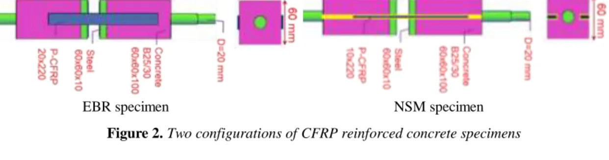
This study aims to investigate the performance of CFRP-concrete bond at different thermo-mechanical conditions. There are several methods that can be found in the literature to determine shear capacity of the joint such as single lap, double lap [CAM 07] [MAZ 08] or even beam test [CHE 05]. In this study, the standard double shear method [FER 10] has been developed with adaptation to the testing device and testing conditions. The double lap testing specimen includes two concrete blocks connected by two CFRP strips using two reinforcement methods: externally bonding reinforcement (EBR) and near surface mounted (NSM) (Figure 2).
EBR specimen NSM specimen
Figure 2. Two configurations of CFRP reinforced concrete specimens
The size of double shear sample has been reduced to meet the limit test apparatus [NGU 18a]. There is a steel bar in the middle welded to another steel plate at bottom of concrete block in order to connect the specimen with two loading heads. The steel plates on the bottom of concrete blocks are designed with the idea to exploit the compressive strength of concrete which is much higher than the material tensile strength (even at elevated temperature condition) and also to reduce the effect of tensile stress on bonded corner of concrete [MAZ 08]. To bond CFRP to concrete, several proposed methods to determine the bond length and width at normal temperature condition has been summarized in previous researches [HOS 14]. The bond-slip model at elevated temperature from 4°C to 180°C has also been proposed and analysed [DAI 13] [GAO 12]. However, most analytical effective
bond lengths exceed the maximum dimension of concrete block (which is limited by dimension of heating chamber). For that reason, to fit with the testing apparatus, the CFRP is bonded to two concrete blocks with two different lengths: anchored length of 90 mm on top part (anchorage bond) and observed length of 70 mm on the bottom part (observed bond, Figure 2) with the failure is expected to happen on the bottom block of concrete. In order to maintain the comparability and feasibility of the different configurations, the geometry of the observed bonded region between CFRP and concrete has been defined to be equal and are 2800 mm2 totally for both sides and the anchorage bonded regions are 3600 mm2. In this study, for NSM configuration, three types of adhesive have been used to bond CFRP on to concrete blocks: two epoxies and one cementitious adhesive. The first epoxy (epoxy 1) is a two-component product which service temperature is introduced up to 350°C for short term applications and 320°C for long term applications. According to supplier’s data, the tensile strength and lap shear strength are respectively 81.4 MPa and 76.5 MPa (at 20°C). The resin’s hardness is classified as shore D95 as ASTM D2240. This adhesive is also used for EBR configuration. The second epoxy (epoxy 2) is a two-component product which is common used with concrete bonding. The shear, tensile and compressive strengths of this epoxy at 20°C are 15 MPa, 29.5 MPa and 83 MPa, respectively. The cementitious adhesive is prepared by mixing cement class of 32.5 with adjuvant to increase workability in concrete slots.
2.1.3. Summary of tests
In this research, the CFRP will be tested following three test processes, a residual test (RR) and two thermo-mechanical tests which are thermo-thermo-mechanical test 1: static thermal test (TM1) and thermo-thermo-mechanical test 2: static mechanic test (TM2). In RR tests, specimens are preheated to the same target temperature levels (Tt) and with the same exposure duration (Tw). They are then naturally cooled in the furnace until stable at ambient temperature. The quasi-static and monotonous mechanical load is then applied to these cooled specimens to failure (Fr). In TM1 test, the temperature rises to desired one (Tt). Once the furnace temperature reaches the target value, it is then kept constant for one desired exposure duration (Tw). The force, applied to the specimen, increases monotonically until the maximum one that the specimen can be resisted (Fr). Finally, in TM2 test, the specimen is firstly loaded with a force called working force (Fw) in the first phase. In the second phase, during while the Fw is maintained, the temperature surrounding the specimen increases with the ramp rate at 30°C/minute from ambient temperature until rupture of the specimen. The temperature, at which specimen is broken, is identified as rupture temperature (Tr) corresponding to the load level Fc. In RR and TM1 condition, direct tensile tests have been carried on CFRP specimens, at different target temperature levels (range from 20°C to 700°C with CFRP and 20°C -300°C with CFRP reinforced concrete specimens) and with a thermal exposure duration (Tw=1 hour with CFRP and 0 minute with CFRP reinforced concrete specimens). Erreur ! Source du renvoi
introuvable. and Erreur ! Source du renvoi introuvable. in the following summary the tests have been
conducted in this studied.
Table 1: Summary of tested series on CFRP
materials
Material Testing condition
20C RR TM1 TM2 P-CFRP X (T=200C, 400C, 500C, 600C) (T=200C, 400C, 500C, 600C, 700C) (Stress ratio =10%, 25%, 50%, 60%, 75%) M-CFRP X (T=200C, 400C, 600C) (T=200C, 400C, 600C) (Stress ratio =10%, 25%, 50%, 60%, 75%)
Table 2: Summary of tested series on CFRP
reinforced concrete specimens Series Method Adhesive** Test program
E N E1 E2 C 20 C RR TM 1 TM 2 1 X X X 2 X X X 3 X X X 4 X X X 5 X X X 6 X X X 7 X X X
(*): E: EBR, N: NSM; (**): E1: Epoxy 1, E2: Epoxy 2, C: cementitious
2.2. Numerical study
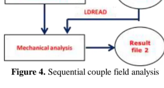
In this numerical study, the NSM configuration of CFRP reinforced concrete specimens is modeled with the mechanical and thermal conditions that are in accordance to the TM2 condition. The purpose is to replicate the condition that is close to fire in term of loading order: mechanical load first and then thermal load. It is expected that the numerical model can be developed for fire studied cases. Due to the symmetry of loading, boundary condition, material and temperature loading, a fourth model was generated and analyzed using the finite element code ANSYS APDL (Figure 3). Building a fourth model can simplify the computation process by reducing elements while maintain the reliability of analysis with time efficiency. In order to simulate the combined effect of
36èmes Rencontres de l’AUGC, ENISE/LTDS, Saint Etienne, 19 au 22 juin 2018 2
temperature and mechanical loadings on CFRP reinforced concrete specimen, the sequential couple-field analysis has been employed (Figure 4). All the thermal boundary condition is first applied on model and then the heat conduction problem has been analyzed to result the temperature distribution among the 3D model. In the second phase, the temperature distribution is then used as load, together with mechanical load applied at different time-result of the first phase, to determine the deformation and displacement of model at each time-step. The collective results at each time-step are then synthesized and thus reflect the response of specimen according to time of heating. During the analysis, the element type chosen for the transient thermal analysis are thermal element SOLID70 for heating phase (3D 8-nodes thermal solid) and SOLID45 for mechanical loading phase (3D 8-nodes Structural solid). To obtain numerical prediction result, the evolutions of thermal properties and mechanical properties of CFRP, concrete, adhesive and also steel material have been adopted from literature [ARR 16] [BIS 03] [FIR 15b] [HAW 09]. During the heating phase, the temperature increase surrounding specimen has been modeled as the temperature evolution in the experimental test.
Tint.N Text.N
Figure 3. Observed part of a fourth symmetry
model with meshed elements (in FE model)
Figure 4. Sequential couple field analysis
3. Experimental results
There are 53 tests on P-CFRP, 33 tests on M-CFRP and 42 tests on CFRP reinforced concrete specimen that had been conducted following three test programs. The experimental results have been synthesized in the following.
3.1. CFRP material.
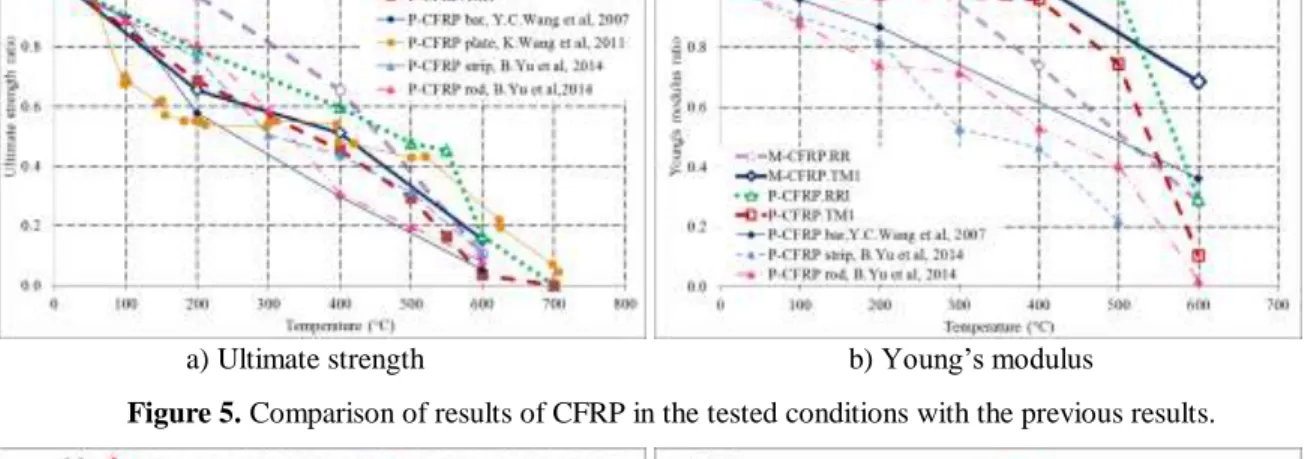
Figures 5 and 6 synthesized the experimental results obtained from CFRP. As can be seen from experimental results with CFRP material, the evolution of the ultimate tensile stress and the Young’s modulus of two types of CFPR (P-CFRP and M-CFRP) as a function of the temperature between 20°C to 700°Chas been experimentally identified. Some findings of this study are mentioned in the followings. Figure 5 shows that the performance of the CFRP material is generally reduced as temperature increases. The thermo-mechanical and residual ultimate strengths of P-CFRP gradually decrease from 20°C to 700°C, while its Young’s modulus varies less than 10% from 20°C to 400°C and then significantly decreases at 600°C. The thermo-mechanical and residual ultimate strengths of P-CFRP decrease by 50% at approximately 300°C and 500°C. The thermo-mechanical and residual Young’s modulus of P-CFRP decreases by 50% at approximately 540°C in the thermo-mechanical procedure and at 570°C in the residual procedure. The evolution curves of the thermo-mechanical properties (both ultimate strength and Young’s modulus) of P-CFRP are lower than the curves of residual properties for temperatures varying from 20°C to 600°C. The differences are minor from 20°C to 400°C but become remarkable from 500°C to 600°C. Similarly, the performances of M-CFRP material generally decrease when the material is exposed to increasing temperatures. The thermo-mechanical and residual strength gradually decreases when the temperature increases from 20°C to 700°C. It loses 50% of its strength at 400°C in thermo-mechanical condition and 45% in residual condition. Meanwhile, Young’s modulus varies little in temperature, ranging from 20°C to 400°C and only decreases 30% at 600°C in thermo-mechanical condition but up to 72% with residual condition. The correlation between thermal and mechanical loads has been experimentally confirmed (Figure 6). The evolution of the failure temperature and exposure duration of a CFRP in the function of mechanical loading (in terms of the stress ratio from 0.1 to 0.75) has been investigated. For both P-CFRP and M-CFRP, when the stress ratio increases from 0.1 to 0.5 (P-CFRP) and 0.6 (M-CFRP), the failure temperature and exposure duration gradually reduces and then significantly scales down when the stress ratio exceeds these values. This result contributes to
the confirmation of the combined effect of thermal and mechanical impacts on the performance of CFRP at the same time. The experimental result of P-CFRP at 400°C in two thermo-mechanical conditions confirm that thermo-mechanical ultimate strength and Young’s modulus of P-CFRP experience little change with thermal exposure durations between 10 minutes and 90 minutes; In addition, the heating rate of exterior condition has small influence on the thermal resistance of P-CFRP at the stress ratio 0.25. The failure mode of CFRP depends on both the exposure temperature and applied mechanical load. As the temperature increases or the mechanical load decreases, the failure of CFRP changes from fragility to a more softened shape. In a practical application of CFRP, the evolution of the failure temperature as a variation of mechanical load can be inferred from the evolution of strength as an increasing temperature and vice versa. In other words, the order of loading among the thermal and mechanical effects on CFRP has little influence on the obtained result. At temperatures higher than the degradation temperature of the CFRP polymer matrix, the CFRP material starts releasing smoke, which is toxic and can disturb the measurement of the material axial strain by the laser sensor. This process can last up to 30 minutes depending on the material composition. The adjusted prediction models [BIS 03] [GIB 05] with the calibrated coefficients can predict the properties of P-CFRP under thermo-mechanical and residual conditions. In addition, a three-degree polynomial analytical model (formula [1]) has been proposed to apply with CFRP (both P-CFRP and M-CFRP) in thermo-mechanical working conditions regarding ultimate strength (Figure 6). The proposed model better fits with two studied CFRPs and other types of CFRP that were reported with thermo-mechanical testing condition. From the authors’ perspectives, proposed model is essentially applicable in the numerical modelling of behaviour of CFRP, in which an elevated temperature and mechanical load are simultaneously applied.
a) Ultimate strength b) Young’s modulus
Figure 5. Comparison of results of CFRP in the tested conditions with the previous results.
a) P-CFRP b) M-CFRP
Figure 6. Correlation between the stress ratio and failure temperature of P-CFRP (a) and M-CFRP (b).
3 , 1 2 ,20 max,10% max,10% u T m m o u C T T T T K K K T T [ 1 ]
In which: Tm is the mechanical glass transition temperature;
T
max,10% is the failure temperature at 10% of the stress ratio; K0 is the coefficient (ranging between 0.4-0.6); K1and K2 are calibrated coefficientsExperimental and numerical study on thermomechanical behaviour of CFRP and CFRP reinforced structures 3
Table 3 summarizes the experimental results of CFRP reinforced concrete specimens obtained in RR and TM1 testing conditions. Figure 7 displays the evolution of residual and thermo-mechanical failure load of CFRP reinforced specimen at different temperatures. According to these results, as temperature increases from 20°C to 300°C, the thermo-mechanical performance of the specimen reduces while its residual performance increases in general (Figure 7). The thermo-mechanical ultimate load quickly reduces 85% when temperature increase from 20°C to 90°C; beyond this temperature, the thermo-mechanical ultimate load then slightly varies until temperature reaches 300C. The residual mechanical ultimate load reduces 68% as temperature increases from 20°C to 75°C. At 150°C, the residual ultimate load significantly increases to reach 1.62 times to ultimate load at 20°C. And at 300°C, the residual ultimate load is greater than that at 20°C about 7%. Table 4 summarizes the experimental result of CFRP reinforced concrete specimens obtained in TM2 condition and Figure 8 displays the thermal performance at different nominal adhesive shear stress (NAS):
w
F S
[ 2 ]In which: is applied tensile force and S is the contact region between CFRP and bottom concrete block and bonded CFRP plates via adhesive
Table 3: Summary of mechanical performance
at different tested temperature conditions Temperature Failure load (N)
RR TM1 C N Normalize d ratio N Ratio 20 17829 1.00 1782 9 1.00 75 13161 0.74 5722 0.32 85 - - 3769 0.21 90 - - 2120 0.12 150 28878 1.62 2787 0.16 300 18997 1.07 1519 0.09
Figure 7. Evolution of failure load at different
temperature conditions
Table 4: Summary of failure temperature at
different configurations and mechanical loads (TM2 condition)
Mechanical Failure temperature, °C
Series 4 5 6 7
Load NAS*** Method* E N N N N MPa Adhesive** E1 E1 E2 C 400 0.143 - 230 838 550 617
840 0.3 - - 544 495 633
1400 0.5 - 135 296 470 -
2800 1.0 - - 224 - -
(*): E: EBR, N: NSM; (**): E1: Epoxy 1, E2: Epoxy 2, C: cement-based adhesive; (***) NAS: nominal adhesive
shear stress.
Figure 8. Evolution of thermal resistance at
different norminal adhesive shear stress (NAS)
As can be seen from Figure 8, as the norminal adhesive shear stress (NAS) increases, the thermal resistance of CFRP reinforced concrete specimen generally reduces. It is shown that at NAS 0.143 MPa, the thermal resistance of series 2 is very high at 838C while those with series 1, 3, 4 are 230C, 550C and 617C respectively. As NAS increase from 0.143MPa to 0.5MPa, the thermal resistances of series 1, 3, 4 slightly reduce while series 2 experiences significant reduction in thermal resistance. For NAS from 0.5 MPa to 1 MPa, the thermal resistance of series 2 reduces more gradually. It is also shown that the thermal performance of NSM configuration is much
higher than that of EBR configuration. With the used epoxy 1 and at NAS of 0.143 MPa, NSM configuration is 4 time higher than EBR configuration in terms of failure temperature. At NAS 0.5 MPa, the failure temperature of NSM configuration is 2.21 times higher than that of EBR configuration. Figure 8 also indicates that the thermal performance of CFRP reinforced concrete specimen is influenced by the used adhesive. It is indicated that, regarding bond efficiency of NSM configuration, epoxy 1 shows better thermal performance than epoxy 2 and cement adhesive at NAS of 0.143 MPa. However, at NAS of 0.3 MPa, cementitious adhesive is slightly greater than epoxy 2 and then epoxy 1. When NAS is increased to 0.5 MPa, the thermal performance of specimen bonded with epoxy 1 is lower than that of specimen bonded with the epoxy 2.
4. Numerical results
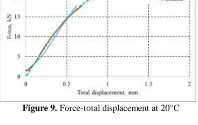
To examine the validity and predictability of the model, the FE and experimental results were compared. Figure 9 shows the force-total displacement of numerical (numeric curve) and two experimental curves (20C-01 and 20C-2). The prediction result is well consistent with experimental results. In the other hand, Figure 10 show the evolution of exterior temperature (T.ext) and interior temperature (T.int) in both numerical case (-.N) and experiment (-.E). The result shows that as the exterior temperature is modeled in accordance to experimental condition, the interior temperature responses are as obtained in the experiment. This shows that the heat conduction problem which has been well modeled.
Figure 9. Force-total displacement at 20C Figure 10. Temperature vs. time at exterior and
interior points
Figure 1. Total displacement- time curves at
different mechanical load cases (TM2 condition)
Figure 2. Prediction of total displacement- time
curves at different mechanical load cases (fire condition, ISO-834)
Figure 11 presents numerical and experimental curves on total displacement vs. time at three different mechanical load cases. The temperature increase in each case was modeled as actual temperature increase obtained in each experiment. The numerical prediction results are well confirmed by experimental results in each mechanical case. Figure 12 show the extended response of the numerical model under 4 mechanical load cases by applying the heating curve in accordance to ISO 834 curve of standard fire. According to Figure 12, at mechanical load Fw= 200N, the NSM configured model, with epoxy 1 adhesive, can resist more than 90 minutes (not shown in figure) while with Fw=400N, the model can resist up to 50 minutes. Accordingly, at Fw=840N, the model can resist up to 35 minutes and at Fw=1400N, the model can resist up to 12.5 minutes.
36èmes Rencontres de l’AUGC, ENISE/LTDS, Saint Etienne, 19 au 22 juin 2018 2
5. Conclusion
From an application standpoint, we would like to impress that in the fire engineering domain, there is little guideline for designing, evaluating the fire performance of general structures (beams, slabs, columns) due to insufficient material data and calculation method. Even in research, the status of structure in a real fire is too complex and thus difficult to thoroughly understand. Among the factors that influence to the structure during fire, mechanical and thermal factors are mainly and simultaneously accounted for the structure failure, so they are the objects of this research. The study has successfully experimentally characterized the performance of CFRP and small concrete structure reinforced by CFRP under three combined temperature and mechanical load conditions. With P-CFRP and M-CFRP materials, the evolution of mechanical properties at different temperature as well as the evolution of thermal resistance at different mechanical load have been identified. Two analytical models have been successfully calibrated with P-CFRP material and an additional model has been proposed and its properness has been validated by two studied materials. The used materials in this research are laminate pultruded CFRP (which is usually used to externally reinforce structures) and M-CFRP (which is usually used to strengthening structure in shear, flexural and confined performance). Therefore, the experimental data can be exploited in structure profiles such as concrete structures (beams, slabs,...), steel (beam,..) reinforced with CFRP. With data from three testing conditions, the case study could be evaluating the performance of structure during-fire with combined impacts of mechanical and thermal effects or post- fire condition. In this study, the performance of CFRP reinforced concrete specimen at thermo-mechanical condition is much lower than the residual one. The mechanical load has compelling impact on thermal resistance of CFRP reinforced concrete specimen. In addition, the NSM reinforcement method shows better thermal performance than EBR reinforcement method under the same mechanical load. Lastly, the use of adhesive has significant influence to thermal performance of CFRP reinforced concrete specimen regarding the same NSM reinforcement method. The numerical model has successfully applied the experimental result on CFRP material in predicting the response of CFRP reinforced concrete specimen under simultaneously combined temperature and mechanical condition. The numerical results show consistence to experimental result in several conditions in both heat transfer problem and also in mechanical response. The extend result is potential to predict the performances of mechanically loaded structures under fire condition.
6. Acknowledgement
This research has been conducted with the financial support of the LMC2 (thanks to its industrial projects) for the experimental works and the financial support of a doctoral scholarship for the first author from the Ministry of Education and Training of Vietnam. We would like to thank technician team (Mr. E. JANIN and Mr. N. COTTET) from the C.E. dep. of the IUT Lyon 1 and the LMC2, University Lyon 1 for their technical support.
7. Bibliography
[ADE 14] Adelzadeh, M., Hajiloo, H., Green, M.F., 2014. Numerical Study of FRP Reinforced Concrete Slabs at Elevated Temperature. Polymers 6, 408–422.
[AL-A 17] Al-Abdwais, A., Al-Mahaidi, R., Al-Tamimi, A., 2017. Performance of NSM CFRP strengthened concrete using modified cement-based adhesive at elevated temperature. Constr. Build. Mater. 132, 296–302. [ARR 16] Arruda, M.R.T., Firmo, J.P., Correia, J.R., Tiago, C., 2016. Numerical modelling of the bond between
concrete and CFRP laminates at elevated temperatures. Eng. Struct. 110, 233–243.
[BAS 76] Bascom, W.D., Cottington, R.L., 1976. Effect of Temperature on the Adhesive Fracture Behavior of an Elastomer-Epoxy Resin. J. Adhes. 7, 333–346.
[BIS 03] Bisby, L.A., 2003. Fire behaviour of FRP reinforced or confined concrete. Queen’s University. [BIS 05] Bisby, L.A., Green, M.F., Kodur, V.K.R., 2005. Response to fire of concrete structures that
incorporate FRP. Prog. Struct. Eng. Mater. 7, 136–149.
[CAM 07] Camli, U.S., Binici, B., 2007. Strength of carbon fiber reinforced polymers bonded to concrete and masonry. Constr. Build. Mater. 21, 1431–1446.
[CHE 05] Chen, J.F., Teng, J.G., 2005. Proceedings of International Symposium on Bond Behaviour of FRP in Structures (BBFS 2005). International Institute for FRP in Construction.
[DAI 13] Dai, J.-G., Gao, W.Y., Teng, J.G., 2013. Bond-Slip Model for FRP Laminates Externally Bonded to Concrete at Elevated Temperature. J. Compos. Constr. 17, 217–228.
[FEI 12] Feih, S., Mouritz, A.P., 2012. Tensile properties of carbon fibres and carbon fibre–polymer composites in fire. Compos. Part A : Appl. Sci. Manuf., Office of Naval Research (ONR): Composites in Fire 43, 765–772.
[FER 10] Ferrier, E., Quiertant, M., Benzarti, K., Hamelin, P., 2010. Influence of the properties of externally bonded CFRP on the shear behavior of concrete/composite adhesive joints. Compos. Part B Eng. 41, 354– 362.
[FIR 14] Firmo, J.P., Arruda, M.R.T., Correia, J.R., 2014. Contribution to the understanding of the mechanical behaviour of CFRP-strengthened RC beams subjected to fire: Experimental and numerical assessment. Compos. Part B Eng. 66, 15–24.
[FIR 15a] Firmo, J.P., Correia, J.R., Bisby, L.A., 2015. Fire behaviour of FRP-strengthened reinforced concrete structural elements: A state-of-the-art review. Compos. Part B Eng. 80, 198–216.
[FIR 15b] Firmo, J.P., Correia, J.R., Pitta, D., Tiago, C., Arruda, M.R.T., 2015. Experimental characterization of the bond between externally bonded reinforcement (EBR) CFRP strips and concrete at elevated temperatures. Cem. Concr. Compos. 60, 44–54.
[FOR 08] Foster, S.K., Bisby, L.A., 2008. Fire survivability of externally bonded FRP strengthening systems. J. Compos. Constr. 12, 553–561.
[GAO 12] Gao, W.Y., Teng, J.G., Dai, J.-G., 2012. Effect of temperature variation on the full-range behavior of FRP-to-concrete bonded joints. J. Compos. Constr. 16, 671–683.
[GIB 05] Gibson, A.G., 2005. Laminate theory analysis of composites under load in fire. J. Compos. Mater. 40, 639–658.
[HAW 09] Hawileh, R.A., Naser, M., Zaidan, W., Rasheed, H.A., 2009. Modeling of insulated CFRP-strengthened reinforced concrete T-beam exposed to fire. Eng. Struct. 31, 3072–3079.
[HOS 14] Hosseini, A., Mostofinejad, D., 2014. Effective bond length of FRP-to-concrete adhesively-bonded joints: Experimental evaluation of existing models. Int. J. Adhes. Adhes. 48, 150–158.
[JAD 17a] Jadooe, A., Al-Mahaidi, R., Abdouka, K., 2017a. Modelling of NSM CFRP strips embedded in concrete after exposure to elevated temperature using epoxy adhesives. Constr. Build. Mater. 148, 155–166. [JAD 17b] Jadooe, A., Al-Mahaidi, R., Abdouka, K., 2017b. Experimental and numerical study of strengthening
of heat-damaged RC beams using NSM CFRP strips. Constr. Build. Mater. 154, 899–913.
[JAD 17c] Jadooe Awad, Al-Mahaidi Riadh, Abdouka Kamiran, 2017. Bond Behavior between NSM CFRP Strips and Concrete Exposed to Elevated Temperature Using Cement-Based and Epoxy Adhesives. J. Compos. Constr. 21 Issue 5.
[KOT 12] Kotynia, R., 2012. Bond between FRP and concrete in reinforced concrete beams strengthened with near surface mounted and externally bonded reinforcement. Constr. Build. Mater. 32, 41–54.
[KOT 08] Kotynia, R., Abdel Baky, H., Neale, K.W., Ebead, U.A., 2008. Flexural strengthening of RC beams with externally bonded CFRP systems: test results and 3D nonlinear FE analysis. J. Compos. Constr. 12, 190– 201.
[MAZ 08] Mazzotti, C., Savoia, M., Ferracuti, B., 2008. An experimental study on delamination of FRP plates bonded to concrete. Constr. Build. Mater. 22, 1409–1421.
[MOU 12] Moussa, O., Vassilopoulos, A.P., de Castro, J., Keller, T., 2012. Time–temperature dependence of thermomechanical recovery of cold-curing structural adhesives. Int. J. Adhes. Adhes. 35, 94–101.
[NGU 18a] NGUYEN P.L., VU X.H., FERRIER E., Characterization of pultruded carbon fibre reinforced polymer (P-CFRP) under two elevated temperature-mechanical load cases: Residual and thermo-mechanical regimes. Constr. Build. Mater. 165, 395–412.
[NGU 18b] NGUYEN P.L., VU X.H., FERRIER E., (2018). Elevated temperature behaviour of carbon fibre-reinforced polymer applied by hand lay-up (M-CFRP) under simultaneous thermal and mechanical loadings: experimental and analytical investigation. Submitted to Fire Safety Journal the 7th January 2018 (current status: under revision).
[NGU 17a] NGUYEN P.L., VU X.H., FERRIER E., 2017. Experimental study on the thermo-mechanical behavior of H-CFRP simultaneously subjected to elevated temperature and mechanical loading, CIGOS2017, HCMC, Vietnam, pp. 484–496.
[NGU 17b] NGUYEN P.L., VU X.H., FERRIER E., (2017). Behaviour of CFRP, with and without fire protection material, under combined elevated temperature and mechanical loading condition. SMAR 2017, Zurich, Switzerland, p. ID109.
36èmes Rencontres de l’AUGC, ENISE/LTDS, Saint Etienne, 19 au 22 juin 2018 4
[NGU 16] NGUYEN P.L., VU X.H., FERRIER E., 2016. An experimental study on the thermomechanical and residual behaviour of the p-cfrp subjected to high temperature loading. CICE 2016, Hong Kong, China, pp. 797–803.
[RED 06] Reddy, D.V., Sobhan, K., Young, J., 2006. Effect of fire on structural elements retrofitted by carbon fiber reinforced polymer composites. 31st Our World Concr. Struct. 16–17.
[SHE 09] Shenghu Cao, Zhis WU, Xin Wang, 2009. Tensile Properties of CFRP and Hybrid FRP Composites at Elevated Temperatures. J. Compos. Mater. 43, 315–330.
[TUR 17] Turkowski, P., Łukomski, M., Sulik, P., Roszkowski, P., 2017. Fire Resistance of CFRP-strengthened Reinforced Concrete Beams under Various Load Levels. Procedia Eng. 172, 1176–1183.
[WAN 11] Wang, K., Young, B., Smith, S.T., 2011. Mechanical properties of pultruded carbon fibre-reinforced polymer (CFRP) plates at elevated temperatures. Eng. Struct. 33, 2154–2161.
[WAN 07] Wang, Y.C., Wong, P.M.H., Kodur, V., 2007. An experimental study of the mechanical properties of fibre reinforced polymer (FRP) and steel reinforcing bars at elevated temperatures. Compos. Struct. 80, 131– 140.
[YUB 14] Yu, B., Kodur, V., 2014. Effect of temperature on strength and stiffness properties of near-surface mounted FRP reinforcement. Compos. Part B Eng. 58, 510–517.