Development of a Portable Educational
Mechatronics Toolkit
by
Peter H.J. How
S.B., Mechanical Engineering (2000)
Massachusetts Institute of Technology
Submitted to the Department of Mechanical Engineering in Partial Fulfillment of the Requirements for the Degree of
Master of Science in Mechanical Engineering
at the
Massachusetts Institute of Technology
May 2003
C 2003 Massachusetts Institute of Technology All rights reserved
Signature of A uthor ...,. ... . . , ... .. .. .. Department of)K echanical Engineering
May 9, 2003
C ertified by... y...
Sanjay Sarma Cecil and Ida Green Associate Professor of Mechanical Engineering Thesis Supervisor A ccepted by... ... Ain A. Sonin MASSACHUSETTS INSTITUTE OF TECHNOLOGY
JUL 0 8 2003
LIBRARIESDevelopment of a Portable Educational
Mechatronics Toolkit
by
Peter H.J. How
Submitted to the Department of Mechanical Engineering on May 9, 2003 in partial fulfillment of the requirements for the Degree of Master of Science in
Mechanical Engineering
Abstract
A portable educational mechatronics toolkit was developed to aid with the teaching of
mechatronics to MIT mechanical engineering undergraduate students. The toolkit was created for use in tlc classroom and laboratory as a teaching aid and outside of the academic environment as a fun, interesting tool. It is hoped that interest in mechatronics will be sparked by "playing" with this toolkit.
The hardware for tle toolkit consists of a PCMCIA data acquisition card, a servo motor controller, servo motors, a stepper motor controller, and stepper motors. These
components are controlled through the use of MATLAB*, Simulink*, and several miscellaneous toolboxes.
The total cost per toolkit for the hardware and software is $1,932. This does not take into account possible educational/bulk discounts or the cost of the required laptop, which the Mechanical Engineering Department already possesses.
The toolkit's current state allows for full use of each component individually, but is not fully functional as a whole integrated system. The toolkit may be run in open- loop control but is not at the point where closed- loop control is possible.
Thesis Supervisor: Sanjay Sarma
Table of Contents 1.0 Introduction...5 2.0 Background...7 3.0 Design Objectives... 10 4.0 Academic Contribution...12 5.0 Competing Products... 14 5.1 Home Automation... . ... 14 5.2 LEGO® M indStorm s*...16
5.3 General Purpose M icrocontroller...21
6.0 Toolkit Development...26 6.1 Data Acquisition... ... . ... 26 6.2 Motor Control...28 6.3 Software Interface... ... 34 7.0 Toolkit Cost...38 8.0 Toolkit Use...39
8.1 Data Acquisition Use... 39
8.2 Servo M otor Control Command Use...43
8.3 Stepper Motor Control Command Use...45
8.4 MATLAB Motor Control Interface...47
8.5 Simulink M otor Control Interface... 51
9.0 Future Work...59
Appendix A: NI DAQCard-AI-16XE-50 (6012E) Parameters ... 63
Appendix B: Servo Motor Controller and Servo Motor Details...70
Appendix C: Stepper Motor Details...71
1.0 Introduction
The average mechanical engineering student is not accustomed to working with
mechatronics outside of the laboratory or classroom environment. Their experience is
limited to running experiments in order to prove theories they have learned in class.
Educators hope that in addition to proving classroom theories, students will also broaden
their general awareness of mechatronics and continue to use mechatronics throughout the
rest of their lives.
Mechatronics does not currently have a place in the home. It does not stir feelings of
amazement that many commercial products do. Yet, in today's technologically advanced
society, mechatronics can be utilized in all facets of our lives to enhance our enjoyment
of life and ease our curiosity with technology. It can play a prominent role in the day to
day activities that we often take for granted, and can be integrated more closely with
education to enhance the learning and teaching experience.
The proposed solution to this problem is to develop a portable educational mechatronics
toolkit for use with a laptop to interface with household appliances/items,
classroom/laboratory experiments, power tools, toys, workout equipment, etc. This kit
would include a range of sensors/transducers, a data acquisition system, servo motors,
stepper motors, and an easy to use software package. It would be versatile enough to
allow users to monitor and control almost anything they desired and have software simple
The expected results are to bring mechatronics into the home and to enhance student's
academic experience by integrating mechatronics into their everyday classes/labs. Uses
for the toolkit would only be limited by the user's imagination and could be used at home for applications ranging from monitoring a hamster's running wheel to controlling a vacuum cleaner to automatically adjust heights depending on tle surface it's currently on.
In the classroom, students might have the opportunity to perform desktop experiments
during lecture and have their results shared over the network instantly for everyone to
2.0 Background
The MIT iCampus project in Mechanical Engineering seeks to bring technology enabled
teaching to the Mechanical Engineering undergraduate curriculum. The project was
started in October of 1999 as a research alliance between MIT and Microsoft Research to
enhance university education through information technology. Through this fund, the
MIT School of Engineering, the MIT Department of Mechanical Engineering, a
Pappalardo faculty endowment, and a donation by Hewlett-Packard, the department has
been able to bring interactive exploration experiments and simulations directly to
student's desks through the use of laptop computers.
The project initially started with 2.001: Mechanics and Materials I and 2.005:
Thermal-Fluids Engineering I, but has spread to include 2.006: Thermal-Thermal-Fluids Engineering II,
2.007: Design and Manufacturing I, 2.008: Design and Manufacturing II, and 2.009: The
Product Engineering Process. In addition, students have used the laptops in 2.671:
Measurement and Instrumentation and several other classes.
For 2.001, the staff has developed an extensive interactive online lecture site that teaches
the fundamentals of mechanics and materials such as friction, bending, torsion, axial
force-deformation, equilibrium, multi-axial stress and strain, truss structures, linear
thermo-elasticity, and energy methods. These web-based learning modules maybe
accessed in the classroom during lecture in addition to outside of lecture at the student's
In addition to the web-based learning materials used in 2.001, 12 desktop experiments
have been developed that cover the entire spectrum of the material taught in class. These
experiments are performed in groups of 3-4 to explore the mechanics concept before it is formally taught in class.
In 2.005, the staff has focused on creating a module that teaches conductive and
convective heat transfer. This module allows students to develop a sense ofhow
temperature distributions develop in solids and liquids throughout time. The staff has
also developed "calculators" to determine the values of Bessel and error functions.
Laptop use in 2.006 was an extension of its function in 2.005 with the exception of several demonstrations utilizing MathCAD*, an applied mathematical software package developed by Mathsoft .
On the other hand, students in 2.007 utilized the laptops primarily for solid modeling.
Students used SolidWorks® and PTC®'s ProEngineer® to create three dimensional solid models and mechanical drawings of the radio controlled robots each individual was
designing and building for the class.
While 2.008 did not use the laptops during lecture, students used the laptops to work on
homework and labs. More specifically, spreadsheet analysis for statistical process
control and solid modeling of injection molded and thermoformed yoyo parts were
The course 2.009 also does not specifically have lectures tailored towards the use of the
mechanical engineering laptops. However, as a senior level course, it is an interesting
class to study the use of the laptops. Many of the students had previously used the
laptops in other semesters and it was intriguing to see the long term effects of laptop use
in the department. As it turned out, students mainly used the laptops for presertatiors
and solid modeling in the class.
Another course not specifically designed for use with the department laptops is 2.671. In
this class, students learn techniques to measure physical variables using laboratory
experiments. Technical laboratory reports generated due to this class were created by the
students on the department laptops. In addition, presentations for the class were also
created using the laptops.
All these courses utilized the laptops for any combination of online lectures,
demonstrations, simulations, spreadsheet analysis, presentations, reports, and solid
modeling. While these are all very useful to a mechanical engineering undergraduate, it
was also hoped that the laptops would be used to a greater extent. It is for this reason that
the mechatronics toolkit of this thesis was proposed.
The toolkit is an extension of the iCampus initiative. Its purpose is to create an
alternative to the software side of the project. The primary motivation was to expand the
scope of the project to include physical hardware in addition to the already developed
3.0 Design Objectives
There were several major design objectives for the portable educational mechatronics
toolkit that were initially set. The hope for the toolkit was that it would be used in the
classroom and laboratory, but also beyond at the student's homes. Students would be
able to start experiments in lab, pack up their toolkits, and continue the experiment at
home.
It is also hoped that this toolkit will spark interest in mechatronics beyond what is taught
in class. The creators of this toolkit would like students to take the initiative and use this
toolkit in their residences to monitor and control anything from appliances to window
blinds.
The hardware of the toolkit will consist of laptop computer, a data acquisition (DAQ)
system, a servo motor controller, servo motors, a stepper motor controller, stepper
motors, and several sensors/transducers. The software used to interact with the toolkit's
components will require no prior programming experience.
In the laboratory, the toolkit will be a partial replacement for existing laboratory
equipment. Students will be able to bring their toolkits to lab and connect them directly
to existing experimental setups. It will then be possible for the students to log data
directly to their own computers and run the ir own motor control and other output device
the student's mechatronics toolkits. These applications demonstrate the necessity for the toolkit to be portable, which is another design objective.
The last design objective is for the toolkit is to be inexpensive. The problems that arise with students carrying extremely expensive equipment in their book bags is
4.0 Academic Contribution
Mechatronics is a little taught subject in the Mechanical Engineering Department.
Currently, undergraduate mechanical engineering students are required to take one main course that teaches controls of electro- mechanical devices. This class is called 2.003:
Modeling Dynamics and Controls I. Students learn Laplace transforms, traisfer
functions, frequency response, Bode plots, modal analysis, open and closed-loop control,
instability, time-domain controller design, and cover a brief introduction to
frequency-domain control design techniques.
The other undergraduate course which teaches mechatronics is an elective course titled
2.737: Mechatronics. This class is laboratory focused and covers such topics as encoder
interfacing, quantization, aliasing, digital logic, electronic feedback, power amplifiers, and motor control.
The toolkit developed for this thesis is an application of these theories rather than a
re-teaching. Students do not directly need to design the controllers for the motors but are
instead able to directly use the data acquisition system and motors for their purposes.
This helps to facilitate a quicker hands-on approach to teach mechatronics. Students will
be able to concentrate on the application of mechatronics rather than the theory behind it.
This is a less focused on angle taught in MIT's undergraduate curriculum. Hopefully, the
results of an attempted/successful mechatronics toolkit project will lead towards an
The portable educational mechatronics toolkit is the only known toolkit of its kind. Other toolkits that are commercially available are either not portable, too expensive, or not powerful enough to fulfill this toolkit's purpose. This toolkit serves as a versatile educational tool that will teach students the subtleties of data acquisition, the intricacies
of motor control, and the importance of the software that ties both together.
The software is a very important part of this toolkit. Almost all software packages that
are available for existing commercial products are packaged with very limited software in
terms of functionality and level of development. The software used for this toolkit, on
the other hand, is extremely versatile, and yet not so complicated that a user is required to
know a formal programming language. The software packages bundled with the other
products limit a user's range of possible activities. For example, one program may only allow a user to control the direction a motor rotates and vary the speed at which it moves.
It does not allow precise motor positioning. Other programs, on the flip side, may control
motor positioning, but will not allow a user to introduce delays or modify other
5.0 Competing Products
There are several products on the market that possess some of the same functionality as the mechatronics toolkit. However, they are not specifically designed to be as versatile or geared for an educational purpose. Several examples of products that perform in some manner similar to the mechatronics toolkit are discussed below.
5.1 Home Automation
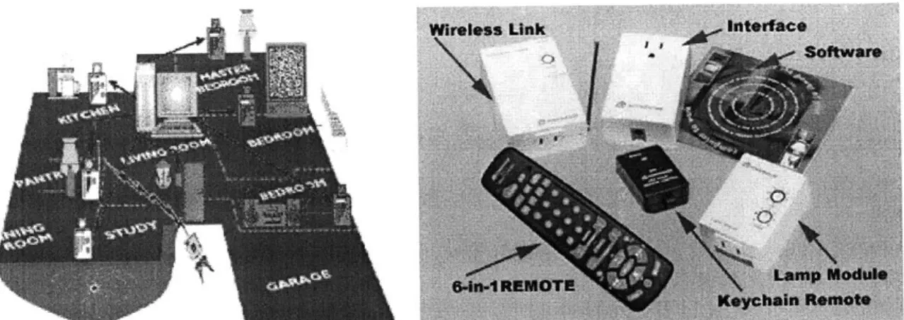
The first of these products is a category ofproduct rather than a specific item The market for the home automation system contains numerous products which fall into this category. Products of this genre may be used to turn on/off lights, control a user's audio/visual system, monitor a security video system, control a heating, ventilation, and air conditioning (HVAC) system, control pool systems, irrigation, etc.
One of the leaders in this category is a company called X10. Many of XIO's products focus on wireless technology and range from wireless video cameras to PC audio/video television transmission Figure 5.0.1, below, shows XIO's ActiveHome Kit which is used to control lights and other appliances. It is initially run from a computer but may be used while the host computer is turned off.
Figure 5.1.1: X1O ActiveHome Kit - PC Control of Lights and Appliances
The difference between a home automation system like X10 and the portable education
mechatronics toolkit is significant. The main difference between the two lies in the
autonomy of the two systems. Unlike the many home automation products, the
mechatronics toolkit cannot be run autonomously. It requires input from a laptop or a
desktop computer at all times. Numerous home automation products, however, are
microcontroller based, allowing control without the need for a computer. This is the most
significant difference between the two products. The mechatronics toolkit could be used
for home automation to turn on/off lights, control a HVAC system, pool system, etc.
However, a significant amount of setup and configuration would need to be done to
accomplish this goal. Home automation products are already optimized to perform these
TM 5.2 LEGO® MindStorms
Another product that is similar to the portable educational mechatronics toolkit is a
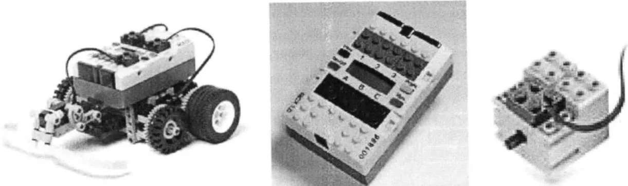
product called MindStorms by LEGO. This product is sold as a kid's toy as a simple
robotics system. The product includes a microcomputer that acts as the brain of tle
product. Sensors and motors can then be attached to the microcomputer and the physical
LEGO structure. An autonomous robot can be created by combining this physical
hardware with a custom designed control program that is downloaded to the
microcomputer.
4f
Figure 5.2.1 (L-R): A LEGO MindStorms Autonomous Robot, Microcomputer Module, MindStorms Motor
The microcomputer programs are created using a very basic software program that is
entirely graphics based. This graphical user interface allows the user to create fairly
complex control algorithms without prior software programming or control theory
experience. Users are able to take inputs from LEGO MindStorms' sensors and actually
information, and output a motor response based on the graphically created
microcomputer program.
The program used to create the microcomputer code is run on a Windows® based
personal computer. The microcomputer program is sent through a USB infrared
transmitter to the MindStorms microcomputer. The LEGO MindStorms robot is then
Figure 5.2.3: USB Infrared Transmission Tower
Several aspects of the LEGO MindStorms product are different from the mechatronics toolkit. The first is the limited amount of sensors available for use by the LEGO MindStorms robot The base LEGO MindStorms system only comes with two touch sensors and a light sensor. In addition, the only other sensors available in the entire MindStorms product line are a rotation sensor, a temperature sensor, and a video camera. This video camera contains a built in microphone and will take 30 seconds of
video/audio. This allows the robot to respond to changes in light, motion, and color.
(a) (b) (c)
(d) (e)
This limited amount of sensors available in the product line restricts LEGO MindStorms
from being an extremely versatile system. Further, the product is handicapped by its
ability to only support 3 sensors inputs to the microcomputer at any one time. On the
other hand, the mechatronics toolkit is able to use any type of sensor/transducer that
emits a voltage and can accommodate numerous inputs far beyond the 3 sensor limit of
the LEGO MindStorms product.
The output of the entire LEGO MindStorms product line is limited to one type of motor,
a light, and one type of pneumatic. In the base MindStorms package, only 2 motors are
provided as output devices. Other systems need to be purchased to obtain altermtive
output devices. In total, a maximum of three output devices may be connected to the
microcomputer at any one time. This severely limits the versatility of the product.
Sensor Channels
Motor Channels
(a) (b)
Figure 5.2.6: a) Light Output Device b) Pneumatic Output Device
Another drawback of the LEGO MindStorms system is the absence in the variety in
motors available. Only one type of motor is available for the entire MindStorms product
line. If a higher torque application were required, a gear reduction would be needed to
obtain the desired torque value. Similarly, if an RPM increase were required, the design
of a gear train would be required to have the output perform at the specified speed. Even
with a gear box, it is not a guarantee that the desired torque/speed is attainable.
The mechatronics toolkit, on the other hand, can control several different types of motors
of varying ratings in addition to any device controllable via a digital 1/0 signal. This
allows the toolkit to be extremely flexible by allowing the use of any number of motors
and output devices.
Another advantage of the mechatronics toolkit is its ability to function as a data
acquisition system. This allows the user to perform data logging and viewing. The
LEGO MindStorms sensors are only able to act as a trigger for the output devices and
audio/visual input. The mechatronics toolkit, on the other hand, is able to take almost any type of data, view it, and save it for an almost infinite amount of time.
5.3 General Purpose Microcontroller
Another way to create a product similar to a mechatronics toolkit is to design and build a
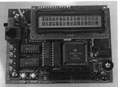
circuit board using a microcontroller. Integrated circuits and other components may be added to control motors, perform analog I/0, digital I/O, and other desired functions. One extremely popular microcontroller based circuit board is called the Handy Board (Martin). This board functions as a general robotics controller and was developed based on MIT's 6.270 Autonomous Robot Design Competition board.
There are numerous products that are commercially available that are microcontroller based. Many have similar functionality to the Handy Board. It is for this reason that only one microcontroller based product, the Handy Board, will be discussed in this thesis.
Figure 5.3.1: Handy Board
The Handy Board is based on Motorola's MC68HC 1 microprocessor. It has 32K of
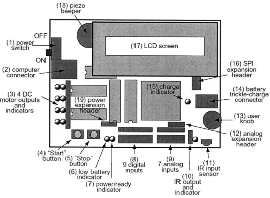
RAM, includes 4 DC motor outputs, 7 analog inputs, 9 digital inputs, infrared I/0, an
LCD screen, and an integrated rechargeable battery pack. It is extremely useful for
(18) piezo beeper OFF (1 power switch ON (2) computer connector (3) 4 DC motor outputs (19) p and n indicators
M
(4) "Start" button (5) "Stop" (8) button 9 digital(6) low battery inputs indicator (7) power/ready indicator ower sion de T
T
(9) 7 analog (1R) inputs IR input (10) sensor IR out ut andt indicatorFigure 5.3.2: Labeled Handy Board Layout
The Handy Board is able to independently control 2 servo motors. The routines used to drive these motors are very basic, but are a functional interface for controlling the motor's position. To control each servo, a specific pulse train needs to be sent to the control circuit to have the servo motor move to the desired position. The duration of the pulse width modulated signal determines the final position of the servo motor shaft. However, in order to have the servo "sweep", specific C code needs to be generated to iterate values over the global position.
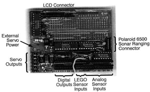
Additional servo motors may be controlled with the addition of Handy Board's
Expansion Board. This board plugs into the top of the Handy Board and provides the
(16) SPI expansion header trck e-charge connector (13) user knob (12) analog expansion header
addition of 10 analog inputs, 4 inputs for active LEGO sensors, 9 digital outputs, and 6
servo motor control signals.
a 0t% I External Servo Power Servo Outputs Polaroid 6500 Sonar Ranging Connector
Digital LEGO Analog Outputs Sensor Sensor
Inputs Inputs
Figure 5.3.3: Handy Board Expansion Board
Stepper motor control with the Handy Board is more difficult. Each time a stepper motor
moves a step, the proper step sequence is required to be sent to the motor. This means
that each step needs to be programmed in to tfr code used to run the motors. More
information specifically about stepper motor control with the Hardy Board maybe found
at http://www.cctc.demon.co.uk/stepper.htm (Harrison).
While the Handy Board is a very versatile circuit board when it comes to robotics, it is
not ideal in terms of teaching motor control and data acquisitionto a mechanical
used to program the microcontroller. Users of the board are required to program code
using assembly language, C, or Interactive C.
Interactive C is a language that was created for the MIT 6.270 LEGO robotic design
competition It is a multi- tasking C language based compiler that allows for dynamic
expression compilation and evaluation. Although developed for student use, Interactive
C still requires students to learn and understand how to program. This is not an ideal
software interface for mechanical engineering students who have little or no prior
programming experience. The complexity in programming the board makes it difficult
for mechanical engineering students to easily control servo and stepper motors, perform
data acquisition, and perform other seemingly simple tasks.
Another disadvantage of the Handy Board is its limited analog input resolution. The
board is only able to handle up to 8 bits of resolution This is not significant enough to
perform functions such as strain gauge measurements, a staple in many mechanical
engineering applications. This lack of resolution makes the Handy Board inadequate for
6.0 Toolkit Development
In the following sections, the development of the portable educational mechatronics
toolkit will be discussed. First, the hardware selection of the data acquisition system will
be discussed, which will be followed closely by the selection of the servo motor
controller and the stepper motor controller. The selection of the software interface will
then be explained in detail.
6.1 Data Acquisition
The hardware used in the toolkit was initially selected based on the functional
requirements of the toolkit; inexpensive, portable, able to perform data acquisition, and
control stepper and servo motors. It was very important to include all of these
functionalities when choosing the specific hardware that would be included in the toolkit.
An additional requirement of having 16 bits of analog input resolution was imposed in
order to properly take readings from strain gauges. This is because several strain gauges
used in the undergraduate curriculum takes discrete readings of -10 to +10 volts. If the
data acquisition portion of the toolkit possessed 16 bits of resolution without a real
programmable gain, this would result in 305.2 micro- volts per discrete interval as seen in
20v 106kp 3 5 2vx I 'V= 3 05.2puv
216 lv
For strains on aluminum, this is acceptable as readings can run in the range of 4000
micro-strain. If the resolution were 12-bits or less, acceptable readings would not be able
to be made.
The 16-bit resolution requirement for the toolkit limited the possible laptop interface for
the data acquisition portion of the toolkit to the PCMCIA slot. This interface also allows
the data acquisition system to have greater sample rates than other laptop interfaces.
Sample speeds of PCMCIA DAQ cards can range into MHz frequencies.
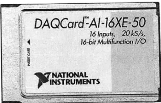
A 16-bit National Instruments (NI) PCMCIA DAQ card was chosen to fulfill the data
acquisition requirements of the toolkit. A major portion of this decision was based on the
intended software that would be used with the toolkit. It was assumed that National
Instrument's LabVIEW and MathWork's MATLAB* would be used extensively in the
development of this toolkit. It was therefore decided that a National Instrument's
DAQCard would be purchased that was supported by MATLAB's Data Acquisition
Toolbox, MATLAB's Real-Time Windows Target, and NI's LabVIEW. The specific NI
card that was chosen was based on the cards that the Data Acquisition Toolbox and
Rea-Time Windows Target supported (see Appendix A). The resulting card was National
Instrumert's DAQCard T M-AI- 16XE-50. Basic hardware parameters for this card are
Analog Digital Counter/ Triggers Inputs Resolution Sampling Range Input Range I/O Timers
16 SE/8 DI 16-bits 20kS/s; 200kS/s ±0.1 to ±lv 8 2, 24-bit Digital single channel
Table 6.1.1: DAQCard-AI- 1 6XE-50 Parameters
Figure 6.1.1: NI DAQCard -AI-16XE-50
Using this card, a student will be able to use any sensor/transducer that outputs a signal
equal to or less than +10 volts. The DAQ card will then digitize the signal and software
will be used to accurately convert the data to the proper engineering units.
6.2 Motor Control
The second portion of the toolkit involves the control of motors. From a controls point of
view, it was decided that the toolkit would be able to control both servo and stepper
determine the best fit for the design goals of the toolkit. Several options presented
themselves that initially seemed like viable solutions. One option was to use a general
purpose microcontroller based product similar to the Handy Board to perform stepper and
servo motor control. Another was to use ready built motor controllers that interface to a
laptop through the serial port or parallel port A final option was to purchase a product
from Animatics called the SmartMotor ", which has an integrated controller and amplifier
within each motor.
From the available options on the market, it was determined that a servo motor controller
would be bought that interfaced to the laptop through the serial port and that the stepper
motor controller would communicate with the laptop through the parallel port. This
would allow both servo and stepper motors to run simultaneously without the need to
change connections.
The primary requirements for the servo motor controller beyond the standard ability to
control servo motors were that it needed to be inexpensive, portable, and controllable
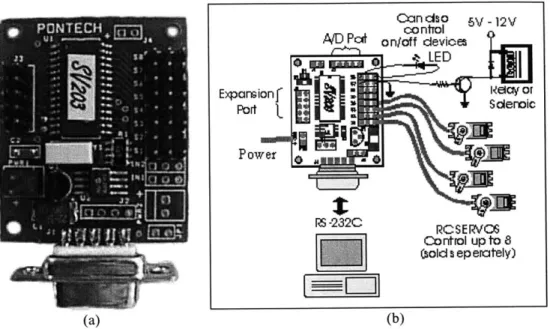
through the serial port. The chosen servo motor controller is a product called the SV203
from Pontech.com which fulfills these requirements. It is a PIC 16C73 microcontroller
based board that accepts RS232 serial data and outputs pulse width modulated signals to
(a) (b)
Figure 6.2.1: a) PONTECH SV203 Servo Motor Controller b) SV203 Connection Diagram
RS232 is an Electronics Industry Standard that was adopted in the 1960s for serial binary
data exchange. Data is transferred one bit at a time from a sender to a receiver through a
single line. This is a form of serial communication and is the standard on many personal
computers, including the laptop used in this toolkit. For this reason, RS232
communication and serial communication will be considered synonymous for the
remainder of this thesis.
The SV203 is designed so that multiple SV203s may be connected to the same line. The
commands to select individual boards and motors, in addition to the commands sent to
position each servo notor, is sent through the computer's serial port in the fbrm of ASCII
character strings. The SV203 processes these strings and outputs the appropriate signal.
Candcs o 5V -12V coontrol AD P onoff devices LED Expansionf Re w or Port Solenaic RS -232C RCSE RVCS Co rtrol up to 8 (sold s ep erately)
The SV203 is compatible with many radio controlled (RC) hobby servo motors with
Futaba J-type connectors. These servo motors contain a built-in potentiometer which
accurately tracks the current position of each servo motor. All RC servo motors will not
work with the SV203. However, many servos without J-type connectors may be rewired
to work properly with the SV203. According to Pontech.com, at the very least, the
servos listed in Table 6.2.1 will work correctly with the SV203 servo motor controller.
CS-10 Cirrus Molecular Micro Ball Bearing Servo
CS-20 Cirrus Sub-Micro Ball Bearing Servo
CS-100 1Cirrus High Torque Retract Servo FP-S148 utaba Rugged Low-profile Servo
Table 6.2.1: Compatible SV203 Servo Motors
In addition to the features mentioned above, the SV203 also includes the following
features:
. Servo control up to 8-bits of resolution (values from 1 to 255)
. Digital output via a reconfigured servo port . Source/sink of 25 mA per pin
. RS232 serial communication of 2400 to 19200 baud
. 5 channels of 8-bit A/D input for analog readings of 0-5 volts . An SPI port for shifting in/out serial data
Similar considerations were taken into account when choosing the parallel port stepper
motor controller. Portability, cost, and the obvious ability to control stepper motors was
paramount in this decision. After an extensive search, a system by Stepperworld.com
mechanical engineering laptop setup. This is because the mechanical engineering laptops
run Windows 2000, which is a Windows NT based operating system. All Windows NT
based operating systems do not allow direct digital I/O to the parallel port without the use
of a specialized hardware driver. Such a driver was not available from the vendor and
third party drivers that were tested with the SP-3/HT system did not work. A decision
was made to therefore purchase a stepper motor controller that communicated with the
laptop through the serial port instead of the parallel port. The obvious disadvantage of
such a decision is the inability to control both servo motors and stepper motors
simultaneously.
The PONTECH STP 100 stepper motor controller was purchased to fulfill the stepper
motor controller role for the toolkit. Each STP 100 board controls one bipolar stepper
motor, but has an onboard multiple drop network connection to allow addressing of up to
255 boards. The STPIOO's stepping logic is driven by a SGS Thompson stepper chip with built in current limiting and step logic. This driver chip is able to supply up to 2
amps per stepper motor. In addition, the STP100 tracks step positions to 32-bits and is
able to drive bipolar stepper motors in full, half, or wave step modes. Further, four
general purpose I/O channels are available for use with the possibility of converting two
of the lines to 8-bit A/D converters. Commands to control the stepper motors are sent via
Figure 6.2.2: PONTECH STP100 Stepper Motor Controller
UWIL
Lim Steppe Mdor RS-232A it Swtches * Ntwork Terminator Logic Power RS-426* I
Network1;-232
SEEKM
1
II
~~n.O4*O[I
L X C1 r 1 1 j t IN E Af " WE9 :Wrn NI q INSS ImnA IThe stepper motor that was initially chosen for use with the toolkit was the Vexta
PK264-01B. However, just about any bipolar stepper motor may be used with the controller that
draws less than 2 amperes of current. In full step mode, the Vexta PK264-O1B rotates at
1.8 degrees per step. In half step mode, this is reduced to 0.9 degrees per step.
Parameters of the Vexta PK264-OB are shown in Table 6.2.2 and geometry and torque vs.
speed graphs are available in Appendix C.
Holding Torque Current per Phase Volts 'Resistance per Phase !Inductance per Phase Rotor Inertia J
(oz-in) (A/phase) (V) (ohm/phase) (mH/phase) (oz-in2)
54. 1 5.7 5.7 5.4 0.66
Table 6.2.2: Vexta PK264-O1B Parameters
6.3 Software Interface
The software interface for the portable educational mechatronics toolkit is an extremely
important aspect of the toolkit. The software needs to be easy enough to use so that prior
programming experience is not necessary. It is also beneficial to be able to use all
functions of the toolkit with one homogenous program, rather than switching between
programs to perform various tasks.
The first requirement of the software is that it needs to be able to control the stepper
motors and the servo motors of the toolkit. It further needs to be able to take data from
the DAQ system, store it, and view. In addition, the software should be able to use tle
There are numerous software packages available that are designed to perform data
acquisition This includes products such as TestPoint, LabTECH, NI-DAQ, LabVIEW,
MATLAB, Personal DaqView, DasyLab, etc. What makes a DAQ software package
more useful in the case of the mechatronics toolkit is the ability to control servo/stepper
motors and to create a closed- loop system between the DAQ card and the motors. Two
software packages distinctly stood out from the rest, not only in terms of the ability to do
this, but also in terms of versatility, amount of use in industry and academia, and ease of
use. These two programs were LabVIEW by National Instruments and MATLAB by
MathWorks. Each package offers certain advantages over the other, but it was MATLAB
that was selected in the end.
MATLAB is a mathematical computing program that integrates visualization into a
powerful language to provide a flexible environment for technical computing. MATLAB
can handle numerous science and engineering tasks from data acquisition and analysis to
application development. With the addition of Simulink, an add-on to MATLAB, a user
is able to build block diagrams, simulate the behavior of a system, evaluate its
performance, and refine its design. It is an interactive tool for modeling, simulation, and
analysis and is extremely useful for control system design, communications systems
design, digital signal processing design, and other simulation applications.
One major advantage of Simulink over many competitors is its friendly programming
environment. A user works entirely within a graphics based environment where blocks
programming experience to develop highly complex models and simulations. When
combined with MATLAB's Data Acquisition Toolbox, Real-Time Windows Target,
Real Time Workshop, and a C compiler, a person is able to create a closed- looped system
and perform real time control of that model.
The Data Acquisition Toolbox for MATLAB is a compiled set of tools for analog input,
analog output, and digital I/O from a range of PC-compatible data acquisition hardware
devices. The toolbox allows a user to configure external hardware devices, take data for
analysis in MATLAB, and output data.
Real-Time Windows Target enables a user to run Simulink models in real time. A user is
able to create and control a real time execution solely through their Simulink model. This
model is converted into C code via Rea Time Workshop, is compiled, and finally
executed in real time while interfacing to hardware connected to the computer. Other
applications will continue to run and may use all CPU cycles not required by the real time
task.
MATLAB is an extremely useful package and is used extensively in industry, academia,
and the MIT Mechanical Engineering Department. This is a major plus for MATLAB as
the department already has a volume license for its use. In addition, undergraduate
students in the department are already familiar with MATLAB as many fundamentals of
the program are already taught in a sophomore level course entitled 2.670: Mechanical
power to solve mechanical engineering problems from solving ordinary differential
equations to outputting the force to displacement matrix of an air cylinder of a robot built
in one of MIT's undergraduate design courses. It is due to this familiarity with the
MATLAB computing environment and MIT's already existing association with the
program that the MATLAB computing environment was chosen as the software interface
7.0 Toolkit Cost
The total cost of a basic portable educational mechatronics toolkit is $1,932. This is
broken down into individual components in Table 7.0.1. The cost can be reduced
significantly by purchasing a less powerful, less expensive PCMCIA DAQ card from
National Instruments or by purchasing a similar but cheaper DAQ product from a
different vendor. The former option, of course, would reduce the capabilities of the DAQ
system of the toolkit. The latter could possibly have issues relating to compatibility.
Item Qty Total Price
Matlab Basic Athena Version 1 $36
Simulink Toolbox 1 $16
Software Real-Time Workshop 1 $36
Real-Time Win Target 1 $22
DAQ Toolbox 1 $26
Microsoft Visual C++ .NET Standard (less with license) 1 $90
NI DAQCard-AI-16XE-50 1 $895
DAQ PR68-68F Ribbon Cable 1 $80
CB-68LP 1/O Connector Block 1 $95
STP100 Stepper Motor Controller 2 $318
Stepper PP232-485F RS232 to RS485 Signal Conditioner 1 $49
PK264-01 B VEXTA 54.2 oz-in. Stepper Motor 2 $152
SV203 Servo Controller 1 $59
Servo Serial Cable 1 $5
CS-100 Cirrus High Torque Retract Servo 1 $25
_Futaba S148 2 $28
Total $1,932
Table 7.0.1: Basic Toolkit Cost
The total cost of the listed toolkit excludes the cost of any transducers/sensors and cost of
the laptop, which the department already has in its possession. Software and hardware
prices do not reflect any volume/educational discounts except for MATLAB and its
8.0 Toolkit Use
The following sections will discuss the operation of the toolkit. Details will be explained
on how to perform data acquisition, servo motor control, and stepper motor control. The
immediately following section will discuss how to perform data acquisition using
MATLAB and Simulink. The next two sections will discuss the format of the commands
used to control the servo and stepper motors; followed by the last two sections, which
will discuss how to perform these commands using the MATLAB and Simulink software
interfaces.
8.1 Data Acquisition Use
Reading data using MATLAB and the NI DAQCard-AI- 16XE-50 requires the use of
MATLAB's Data Acquisition Toolbox. Further, to take data entirely within a graphically
based environment, the addition of Simulink is required. The commands below may be
used to acquire data directly from MATLAB without the use of Simulink. An M-file
may be created to run these commands or entered individually into the MATLAB
command prompt. Next to each example command is an explamtion of that command's
ai = analoginput('nidaq'); addchannel(ai,0, 1); set(ai,'SampleRate', 10) ActualRate = get(ai,'SampleRate'); set(ai,'SamplesPerTrigger', 150) set(ai,'LoggingMode','Disk') set(ai,'LogFileName','datal.daq') start(ai) data = daqread('datal.daq') plot(data)
%Creates an analog input
%Add channels to object "ai"
%Set sample rate to 10 Hz
%Retrieve actual sample rate (could be %different from the specified value) %Set the amount of samples taken %Set the data logging mode %Set the data file name %Start the data acquisition
%Retrieve the data from the saved file %Plot the data on a graph
To learn about other commands and options to take data in MATLAB, please see the
Data Acquisition Toolbox website at http://www.mathworks.com/products/daq/ or view
the MATLAB help file found within the MATLAB program.
To acquire data in Simulink, a model needs to be created which connects the DAQ
hardware inputs to the intended outputs. A very basic example Simulink model where an
analog input from the DAQCard-AI- 16XE-50 is taken and displayed on the scope is
shown in Figure 8.1.1, below.
Analog In put
Analog Input Scope
National Instruments DAQCard-Al-16XE-50 [auto]
Figure 8.1.1: Basic DAQ Simulink Model
To take data in real time from a DAQ device such as the NI DAQCard, Simulink in
addition to MATLAB's Real- Time Windows Target, Real-Time Workshop, and a C
application in real time allows greater flexibility by granting access to parameter tuning and signal tracing in a real time run. A more complex Real-Time Windows Target example application is shown in Figure 8.1.2.
DA
Analog 2, 10000
Input s2+70s+10000
Analog Input Transfer Fcn
National Instruments DAQCard-Al-16XE-50 [auto] L- T Clock To Workspace2 T Digital Output Digital Output National Instruments OCard-AJ-16XE-60 [auto] Scope channell o Woikspacel channelO o Woikspace
Figure 8.1.2: Example Simulink Data Acquisition Model
In this example, one analog input is taken, passed through a transfer function, sent to the scope for viewing, and then sent to a MATLAB workspace. That same analog input is also outputted to a digital out on the DAQCard which is then read by the DAQCard's
second analog input. This second analog input is sent simultaneously to the scope for
viewing and sent to the workspace. The data from the workspace can then be used after
the simulation is paused or stopped by retrieving that data using the "From Workspace"
Simulink block. The resulting scope of a randomly pulsed analog input to channel 1 is
displayed in Figure 8.1.3, below. The upper graph represents analog channel 1 while the
Figure 8.1.3: Resulting Scope of the Example Simulink Model from Figure 8.1.2
This model is different from a non-real- time simulation in several ways. First, a user is
able to capture and display signals from a real time application while it is still running.
The data is retrieved from the application and disphyed in a model's scope block in real
time. Second, the model parameters may be changed and implemented on the fly. These
parameters may be altered in the Simulink block parameters, the block parameters for
masked subsystems, and in the MATLAB variables used to represent model parameters.
The third difference between this application and a non-real-time application is the ability
to take data from the input, immediately process that data, and then use that data to
trigger an output to an external hardware device. In this case, that device is the digital
8.2 Servo Motor Control Command Use
The chosen stepper motor controller and servo motor controller accept ASCII string
inputs as commands to control their respective motors. Both the SV203 servo motor
controller and STP 100 stepper motor controller processes commands one ASCII string at a time.
The SV03 servo motor controller accepts ASCII commands in the form ofL n Ln ...
<enter>. Each L stands for a letter or letters while the n is a decimal integer. An
example of a set of commands that selects a controller board (BDn), selects a servo motor
(SVn), and then moves that motor to a specific position (Mn) could be represented with
the following commands:
BD 1 SV4M 150 <enter>
These commands could also be separated by spaces or commas for easier reading.
BDI SV3 M85 <enter>
BDl,SV3,M85 <enter>
BD 1 SV 3 M 85 <enter>
A full list of summarized commands for the PONTECH SV203 controller is shown in
Figure 8.2.1, below. Most commands are self explanatory. However, it should be noted
that a carriage return is required at the end of each string to signal to the controller to
For further details on how to setup the controller board and an explanation of the
commands in detail, please see the PONTECH SV203 manual which can be found at
http://pontech.com/products/sv200/index.htm.
Commands
Parameter
Description
,(n)
BDn 0 to 255 Board Select SVn 1 to 8 Servo Select
Mn 0 to 255 Move to an absolute location In -128 to 127 Move relative to current position
Un 1 to 65535 Delay (ins)
PSn 1 to 8 Put, set single pin of servo port
PCn b is a number between 1 and 8, which tells P'in what pin on the port is being used.
Ifn=0 4 clear Bit n=1 4Set Bit n= 2 4 Toggle Bit
ADn 1 to 5 Get A/D value, the board will return a value
between "0" to "255" followed by ASCII 13
which represent a voltage between 0 to 5 Volts.
SOn 0 to 255 Shift a byte out to the SPI port SI None Shift a byte in form the SPI port WRm n m= 0 to 255 Write to internal RAM
n 0 to 255 m is the memory location
n
is the value to writeRRm m= 0 to 255 Read the contain of internal RAM m is the memory location to read WEm n n =0 to 8190 Write to external EEPROM
n= 0 to 255 m. is the memory location n is the value to write
R.Em n = 0 to 8190 Read the contents of external EEPROM m is the memory location to read
None Help, return summary of command listing V? None Returns the firmware version
8.3 Stepper Motor Control Command Use
The STP 100 stepper motor controller also accepts ASCII string commands one string at a time. Each string must end with a carriage return or <ASCII 13>. This tells the
controller board to process the command string. The command format accepted by the stepper motor controller board has two forms: Ln Ln Ln ... <enter> or L L L... <enter>.
The L in this case stands for a letter or letters while the n stands for an integer. An example of a command that selects a board (BDn), sets the step delay (SDn), and moves the stepper motor to an absolute position (MIn) is below.
BD 1 <enter>
SD1000 <enter>
MI320 <enter>
Multiple commands up to 20 characters long may also be entered in one command string. These commands may be strung together directly one after another or separated by commas or spaces.
BD 1 SD 1 000MI320 <enter> BD 1 SD1000 M1320 <enter> BD1,SD1000,MI320 <enter>
It should be noted that once a board is selected, it remains selected until another board is selected or the power is turned off. Also, a minimum delay of three milliseconds should be given between commands to give the controller time to process the command. A summary of all possibly commands for the STP 100 stepper motor controller is shown in
and other information, please see the PONTECH STP 100 manual at http://pontech.com/products/stp100/index.htm
Command Parameter Descrlptlon
Figure 8.3.1: PONTECH STP100 Command Summary
BDn N = 0 to 255 Board Select
Min N = -2147483648 Move Immediately to an absolute location to 2147483647
MCni N = -2147483648 Move on Cue to an absolute location (must be to 2147483647 followed by CU command)
lini N = -2147483648 Move Immediately relative to current position to 2147483647
ICn N = -2147483648 Move on Cue relative to current position cue to 2147483647 (must be followed by CU command)
CU None Cue a move
Pn N = 3. 5, 6or 8 Pin clear on 10-pin header PSn N = 3, 5, 6, or 8 Pin set on 10-pin header
RPn N = 3, 5, 6, 8 or Read Pin on 10-pin header (if n is not specified,
None a four bit value is retumed representing all pins)
ADn N = 1 or 2 Get AD value, the board will return a value betveen "0" to "255" which represents a voltage between 0 to 5 Volts.
WRmn n M = 0 to 255 Write to internal RAM, m is the memory
N = 0 to 255 location n is the value to write
WEm n M = 0 to 8190 Vrite to external EEPROM, m is the memory
N = 0 to 255 location n is the value to write
WSS None Write System Settings to EEPROM (current
value of SD. SM. SA, SH, SF, SW, SP SP are stored to EEPROM)
RRm M = 0 to 255 Read the contain of internal RAM, m is the
memory location to read
REm M = 0 to 8190 Read the contain of external EEPROM, m is the memory location to read
RC None Read Current Position
RD None Read Destination Position
RT None Read delTa Position (DestinationPosition
HIMn n = -2147483648 Set new home position, current position = to 2147483647 destination position = n
HI None Halt Immediately, set destination position to
current position and do not decelerate
H0 (H - Zero) None Halt. Set speed to 0 and decelerate
H+ None Move Clockwise forever
H- None Move Counter-Clockwise forever
SP None Stepper Always powered
SO None Stepper Off when not moving (Remove power
from stepper, no holding torque)
SH None Set Half Step mode
SF None Set Ful Step mode SW None Set Wave Step mode
TCn n = 3, 5, 6, or 8 Test if pin clear, on clear execute HO TSn n = 3, 5, 6, or 8 Test if pin set, on set execute HO
RSA None Read Step Acceleration/Deceleration Factor
RSD None Read Step Delay
RSM None Read Minimum Step Delay Factor
SAii n = 1 -255 AccelerationiDeceleration Factor
SDn n = 6 to 65535 Step Delay (n x 1.6us)
SMn n = 0 to (65535 - Minimum Step Delay Factor (Start Step Delay SD) = StepDelay + MinimumStepDelayFactor) if=
0 then no acceleration
Figure 8.3.2: PONTECH STP 100 Command Summary
8.4 MATLAB Motor Control Interface
The servo motor and stepper motor controllers require ASCII string inputs for motor control In order to control the servo motor and stepper motors through MATLAB, it is required that MATLAB be able to send ASCII strings through the serial port. This can be accomplished through the use of the MATLAB command "fprintf'.
First, however, an object needs to be created that represents the serial port device. In our case, this is a motor controller. That object then needs to be connected in order to send
ASCII string outputs. Only after the object is created and connected will MATLAB
properly send ASCII strings through the serial port The commands below serve as an example that will allow a user to control the servo and stepper motors. The string between the quotation marks in the fprintf command line may be substituted with other motor controller commands. Next to each command is a brief description of what that particular command does. These commands may be entered into a MATLAB M- file or entered individually into the MATLAB command prompt.
s = serial('COMl'); %Create a serial device object from COMI of the computer fopen(s); %Connect the serial device object
instrfind %Return serial port objects from memory (lets you know s is %actually open)
fprintf(s,'%s\n\r','BDO SVl') %Writes the string within the quotation marks to s
The fprintf command shown above is in the form of fprintf(obj,format','cmd'). The obj in this case is "s", the format is "/os\n\r", and the ASCII command is "BDO SVl "(select board 0, select servo motor 1). The "/os" in the format area designates the notation of the output as an ASCII string. The "\n" symbolizes a new line and the "\r" represents a carriage return. Specifics about the fprintf command and additional options may be seen
in the MATLAB help file or online at
http://www.mathworks.com/access/helpdesk-rl2pl/help/techdoc/ref/fprintfserial.shtml.
The object "s" is required to only be created and connected once. Any further commands
MATLAB function. For example, to move servo motor 2 on board 1 to position 200 and
then to position 60, the following commands could be used. This assumes that the serial object has not yet been created or connected.
s = serial('COM 1'); %Create a serial device object from COMI of the computer fopen(s); %Connect the serial device object
instrfind %Return serial port objects from memory (lets you know s is %actually open)
fprintf(s,'%s\n\r','BD1 SV2') %Selects board 1 and servo motor 2 fprintf(s,'%s\n\r','M200') %Moves servo motor 2 to position 200 fprintf(s,'%s\n\r','M60') %Moves servo motor 2 to position 60
Note that the M200 and M60 commands could have been sent on the same ASCII string
with a delay in between. The board and servo motor select, however, is required to be sent before the initiation of a move operation. This is only true for the SV203 servo motor controller. The STP 100 stepper motor controller allows the board select to be sent in the same command string as a mve command. An example for the STP 100 stepper motor controller may be seen below. It is assumed that the object device has already been created and connected.
fprintf(s,'%s\n\r','BD1 MIl00') %Selects board 1 moves the associated motor to position 100
This command will only work after the board IDs are properly associated with the
appropriate controller board. When this command is sent to the stepper motor controller
immediately after powering up the controller board, not only will motor 1 move to
position 100, but so will the other motors. In the case of the 2 stepper motors that are
also true if board 2 were selected after initially powering up the controller board instead
of board 1.
However, if a BD2 command were sent after initially issuing a BD1 command, then that particular motor associated with board 2 will move independently of board 1. This also works when starting with a BD2 command and then sending a BDl command. After sending this second BDn command to the stepper motor controller, issuing a BDI or BD2
command will independently be associated with the correct board for the remained of the
time that the power is connected to the controller. Further, once the commands are
correctly associated with each board, a BDO command will link together both of the
current stepper motor boards causing future move commands associated with a BDO
command to control both motors in exactly the same fashion.
If a BDO command were initially sent with a move command immediately after powering
up the controller boards, the motor associated with board 2 will move, and not the motor
associated with board 1. If a BD2 command were then sent followed by a move
command, the motor associated with BD2 will move independently of motor 1.
Following this, all BDO commands will cause both motors to move together.
If a BD 1 command were issued after initially starting with a BDO command, then the
motor associated with BDl will move independently of board 2's motor. Similarly, after
this, all future move commands will be associated correctly with the appropriate
controller board. These are little, but workable, nuances associated with this stepper
The last nuance about the STP 100 deals with the move on cue (MCn) command. All cue commands for each motor are required to be sent separately. Then when a BDO CU is issued, all the motors will start at the same time. For example, the following move on cue command will not work. This is assuming that board selection is appropriately assigned and that the serial port object has already been created and connected.
fprintf(s,'%s\n\r','BD1 MC400 BD2 MC700 CU')
Instead, the move on cue command should be sent as follows.
fprintf(s,'%s\n\r','BD1 MC400') fprintf(s,'%s\n\r','BD2 MC700') fprintf(s,'%s\n\r','CU')
This will cause the stepper motor associated with board 1 to move to absolute position 400 at the same time that motor 2 moves to position 700.
8.5 Simulink Motor Control Interface
The purely MATLAB motor control interface presented in section 8.4 is an open- loop process. Commands may be sent to the controllers, but no feedback or external inputs
may be used to close the loop or act as a trigger. To be able to have this functionality in
MATLAB, it needs to be possible to take real time input from the DAQCard and have
to take data from an analog input and have that trigger an output. However, the problem is that the output cannot be an ASCII string. This is due to the fact that Simulink,
including all of its toolboxes, cannot output ASCII strings. The only available data types that can be output ted are listed in Table 8.5.1.
Name Description
double Double-precision floating point single Single -precision floating point int8 Signed 8-bit integer
uint8 Unsigned 8-bit integer int.6 USigned 16-bit integer intl6 Signed 16-bit integer int32 Signed 32-bit integer uint32 Unsigned 32-bit integer
Table 8.5. 1: Simulink Built-in Data Types
A work around solution to this problem is to program an S-function (system-function).
An S-function is a mechanism that allows a user to extend the capabilities of Simulink by adding user defined blocks to a Simulink model. These blocks may be created in
MATLAB, C, C++, Fortran, or Ada. Specific algorithms may be implemented by an S-function by following a set of rules provided by MathWorks, the creators of MATLAB and Simulink. S-functions are also compatible with Real- Time Windows Target and have customizable user interfaces through the use of masking.
Fortunately a free S-function that writes ASCII strings to the serial port has been programmed in C++ by a third party MATLAB user. This package called the "RS232
Blockset" (Daga). The RS232 Blockset was initially created to support a project on the
avionics of a simulated aircraft. Luckily, this blockset may also be used for general
RS232 communication. Unluckily however, the blockset has never worked properly with
the portable education mechatronics toolkit.
The RS232 Blockset is composed of the 11 blocks seen in Figure 8.5.1. The two
important blocks of concern for this mechatronics toolkit are the RS232 Setup block and
the RS232 Write String block. The setup block creates a serial device object, connects it,
and closes it after the simulation is completed. The RS232 Write String block outputs
ASCII strings through the computer's serial port. For each simulation step that the input
flag of the RS232 Write String block is a Boolean 1, the designated ASCII string will be
sent. Each time a Boolean 0 is inputted to the block, the ASCII string will not be sent.
RS232 Blockset Library 1.1