Adaptive Feedforward Cancellation Viewed from
an Oscillator Amplitude Control Perspective
by
Joseph Harry Cattell
B.S., Mechanical Engineering (2000)
University of Pittsburgh
Submitted to the Department of Mechanical Engineering
in partial fulfillment of the requirements for the degree of
Master of Science
at the
MASSACHUSETTS INSTITUTE OF TECHNOLOGY
May 2003
@Massachusetts
Institute of Technology 2003. All rights reserved.
Author ...
Department o 4echanical Engineering
May 9, 2003
Certified by ...
David L. Trumper
Associate Professor of Mechanical Engineering
Thesis Supervisor
A ccepted by ...
Ain A. Sonin
Chairman, Department Committee on Graduate Students
MASSACHUSETTS INSTITUTE
OFTECHNOLOGY
JUL 0 8 2003
Adaptive Feedforward Cancellation Viewed from an
Oscillator Amplitude Control Perspective
by
Joseph Harry Cattell
Submitted to the Department of Mechanical Engineering on May 9, 2003, in partial fulfillment of the
requirements for the degree of Master of Science
Abstract
This thesis presents methods of characterizing the convergence, error, stability, and robustness properties of Adaptive Feedforward Cancellation (AFC) for use on fast tool servos in high-precision turning applications. Previous work has shown that classical control techniques can be used to analyze the stability and robustness of an AFC loop. However, determination of the convergence and error properties of the closed-loop system to changes in the reference or disturbance signal is not an obvious output of these analyses. We have developed a method of viewing AFC from an oscillator amplitude control (OAC) perspective, which provides additional use of classical control techniques to determine the convergence and error properties of the closed-loop system.
AFC is a form of repetitive control that can be used to significantly improve peri-odic trajectory following/disturbance rejection. Fast tool servos used in high-precision turning applications commonly follow periodic trajectories and develop large errors, which usually occur at integer harmonics of the fundamental spindle rotation fre-quency. We have developed a loop-shaping approach to designing multiple resonator AFC controllers and have implemented this design on a commercially available piezo-electric (PZ) driven FTS using a PC-based digital control system.
Our view of Adaptive Feedforward Cancellation from an oscillator amplitude con-trol perspective builds upon previous work in the literature. We use an averaging analysis to simplify the single resonator AFC system into two coupled single-input single-output (SISO) oscillator amplitude control loops and show that by using the correct rotation matrix, these loops are effectively decoupled. This simplification pro-vides the use of classical control techniques to approximate the dynamics of the closed-loop output to changes in the amplitude or frequency of the reference/disturbance signal. The simulated and experimental results conform well to our analytical pre-dictions for sufficiently low gain values.
Thesis Supervisor: David L. Trumper
Acknowledgments
I would first like to thank my advisor Professor David L. Trumper. He continually challenged me to work at my full potential, and helped me learn to look at things from a new perspective. It has been an honor working with him over the past two years. Next, I would like to thank all of my colleagues in the Precision Motion Control Lab. This includes Marten Byl, Katie Lilienkamp, Xiaodong Lu, Rick Montesanti, Vijay Shilpiekandula, Andrew Stein, and Dave Otten. I cannot single out any one of them, since each person helped me tremendously during my time here at MIT. It has also been an honor and privilege working with them and I wish them all the best in the future. Maggie Beucler and David Rodriguera were also a tremendous help with taking care all of the administrative needs I had.
For the times not spent in Lab, I am thankful for the friendships I developed with Ahmed Elmouelhi, John Mcbean, and I-hsiang Shu. I truly enjoyed the times I spent with each of them, even if we had to eat at Old Country Buffet. Also, I would like to thank Dr. Ivan Salgo. I will always remember the many conversations we had and the guidance he has given me. He has been a great friend, as well as one of my role models.
Finally, I would like to thank my family for all of their support and understanding over the past two years. My time here at MIT has been a bumpy ride and I don't think I would have made it without them. Most importantly, I would like to thank my fiance April Kalix. For the past two years, MIT consumed almost all of my free time. Although in completely different locations, we were able to make it work. I am anxiously looking forward to spending the rest of my life with her.
Contents
1 Introduction 23
1.1 Project Sum m ary . . . . 23
1.2 Thesis O verview . . . . 36
1.3 B ackground . . . . 36
1.3.1 Rotary Fast Tool Servo for Diamond Turning of Asymmetric O p tics . . . . 37
1.3.2 Self-Tuning Narrow-Band Trajectory Following & Disturbance Rejection Control Systems . . . . 38
2 Adaptive Feedforward Cancellation Systems Theory 53 2.1 B ackground . . . . 54
2.1.1 Review of Classical Control . . . . 54
2.1.2 Repetitive Control Systems . . . . 57
2.2 Adaptive Feedforward Cancellation . . . . 65
2.2.1 Derivation of the Estimates of the Fourier Coefficients . . . . . 68
2.2.2 Equivalence of the AFC Algorithm to an LTI System . . . . . 73
2.2.3 Phase Advance Parameter O$ . . . . 80
2.2.4 Example of Single Resonator AFC Controller Implementation 96 2.2.5 Convergence Properties of Adaptive FeedForward Cancellation 100 2.2.6 Multiple Resonator Adaptive Feedforward Cancellation Systems 112 2.3 Adaptive Feedforward Cancellation Summary . . . . 137
3 Experimental Controller Design 139 3.1 Hardware Evaluation . . . . 140
3.2 Control System Implementation . . . . 146
3.3 Preliminary Controller Design . . . . 148
3.4 Preliminary Controller Design with Inner Charge Loop . . . . 168
3.5 Higher Bandwidth Controller Design . . . . 176
3.5.1 Controller Design with the LVDT Feedback Sensor . . . . 179
3.5.2 Controller Design with the Kaman Instrumentation Inductive Sensor ... ... 189
3.6 Adaptive Feedforward Cancellation Controller Design . . . . 197
3.6.1 Single Resonator AFC Controller . . . . 199
3.6.2 Two Resonator AFC System . . . . 204 3.6.3 Multiple Resonator AFC System with Command Pre-Shifting 208
3.7 Sum m ary . . . 216
4 Oscillator Amplitude Control Systems Theory 219 4.1 Sinusoidal Oscillators ... ... 219
4.1.1 Wien-Bridge Oscillator . . . 220
4.1.2 Quadrature Oscillator . . . . 221
4.2 Oscillator Amplitude Control . . . . 222
4.2.1 Background . . . 222
4.2.2 Quadrature Oscillator Amplitude Control System . . . . 224
4.2.3 Example of an Oscillator Amplitude Control System . . . . . 229
4.3 Sum m ary . . . . 234
5 Adaptive Feedforward Cancellation Viewed from an Oscillator Am-plitude Control Perspective 237 5.1 Simplified Sine Channel of the Single Resonator AFC Controller . . . 239
5.2 Example of AFC viewed as an OAC System . . . . 253
5.3 Limitations of the Oscillator Amplitude Control Perspective . . . . . 256
5.3.1 First Order Perturbation Analysis . . . . 256
5.3.2 Oscillator Amplitude Control Perspective with Slow Plant Dy-nam ics . . . . 263
5.4 Adaptive Feedforward Cancellation viewed as a Input Multiple-Output Oscillator Amplitude Control System . . . . 268
5.4.1 Single Resonator AFC System viewed from an OAC Perspective 270 5.4.2 Multiple Resonator AFC System viewed from an OAC Perspective281 5.5 Error Properties of AFC viewed from an OAC Perspective . . . . 287
5.5.1 Example of a Single Resonator AFC System with Time-Varying Input Amplitude Components . . . . 288
5.6 Sum m ary . . . . 293
6 Conclusions and Suggestions for Future Work 295 6.1 Sum m ary . . . . 295
6.2 Suggestions for Future Work . . . . 296
6.2.1 Variform FTS Experimental Controller Design . . . . 296
6.2.2 Adaptive Feedforward Cancellation . . . . 298
6.2.3 Adaptive Feedforward Cancellation viewed from Oscillator Am-plitude Ccontrol Perspective . . . . 300
6.3 C onclusions . . . . 301
A Variform FTS Pictures & I/F Board Schematic 303
B State Space Matrices for Gp1(s) 307
C State Space Matrices for GP2(s) 309
E State Space Matrices for Rotary Fast Tool Servo 313
F AFC resonator Values 315
G Description of Altered MATLAB Simulink DSA Block 317
H Listing of Command Pre-Shifting Frequency Response MATLAB
Code 319
I State Space Matrices for MIMO OAC Model 327
J State Space Matrices for Altered MIMO OAC Model 331
List of Figures
1-1 Picture of the Variform FTS and experimental hardware. . . . . 24 1-2 Close-up picture of the Variform FTS. . . . . 24 1-3 Pictures of the Variform FTS actuator. . . . . 25 1-4 Single resonator AFC control loop with the phase advance parameter
Oi im plem ented . . . . 26 1-5 Control loop configuration used with the Variform FTS . . . . 28 1-6 Calculated negative of the loop transmission frequency response for the
Variform FTS with a ten resonator AFC controller. . . . . 29 1-7 Experimental FTS closed-loop frequency response from reference to
output with a ten resonator AFC controller and command pre-shifting feedforward channel. . . . . 30 1-8 Comparison of the experimental closed-loop error signal with and
with-out A FC Control. . . . . 31 1-9 Experimental and simulated transient responses of a single resonator
AFC system designed to follow a reference signal with wi = 50 Hz. . . 32 1-10 Closed-loop block diagram for the single resonator AFC system viewed
as a multiple-input multiple-output (MIMO) oscillator amplitude con-trol system . . . . 34 1-11 Simulated transient response of a single resonator AFC system
de-signed to cancel a constant amplitude disturbance with wi = 180 rad/sec. 35 1-12 Higher Harmonic Control closed-loop block diagram. . . . . 42 1-13 Active Magnetic Bearing closed-loop block diagram with Automatic
Vibration Rejection. . . . . 45 1-14 Summary of Automatic Vibration Rejection in block diagram form. . 46 1-15 Automatic Vibration Rejection algorithm. . . . . 47 1-16 Active Magnetic Bearing closed-loop block diagram with Automatic
Vibration Rejection converted into an AFC equivalent form. . . . . . 47 1-17 Automatic Vibration Rejection algorithm in an AFC equivalent form. 48 1-18 Principle of the AVR unbalance compensation algorithm. . . . . 49 2-1 Classical feedback system closed-loop block diagram. . . . . 55 2-2 Closed-loop block diagram manipulated into a unity feedback notation. 56 2-3 Example frequency response for lead-lag compensator with lag pole at
the origin (s= 0). . . . . 57 2-4 Example of the frequency response of an Internal Model Principle
2-5 Calculated negative of the loop transmission frequency response with ten IMP controllers placed in parallel . . . . . 61 2-6 Simple repetitive controller periodic signal generator. . . . . 63 2-7 Example of a frequency response for a time-delay repetitive control
system . . . . . 64
2-8 Altered repetitive controller periodic signal generator block diagram with a low-pass filter q(s). . . . . 65 2-9 Example of a frequency response for a time-delay repetitive control
system with a q-filter. . . . . 66
2-10 Plant transfer function P(s) with a periodic disturbance input d(t). . 67
2-11 Adaptive periodic disturbance rejection block diagram. . . . . 67
2-12 System containing a Strictly Positive Real transfer function. . . . . . 68 2-13 Altered adaptive disturbance rejection figure with the block diagram
implementation of the equations for the estimates of the Fourier
coef-ficients ai(t) and bi(t). . . . . 72 2-14 LTI equivalent single resonator AFC controller closed-loop block diagram. 73
2-15 Single resonator AFC controller closed-loop block diagram with the
phase advance parameter qi implemented. . . . . 74
2-16 Example of a frequency response for a single resonator AFC controller
without the phase advance parameter i . . . . 81 2-17 Frequency following compensator block diagram. . . . . 83 2-18 Comparison of the methods of phase advance implementation on the
single resonator AFC controller. . . . . 86 2-19 Pole-zero map of a single resonator AFC controller as the phase
ad-vance parameter is varied between -11 <
#i
< ... . . .. . . ..872-20 Illustration of the locations of the AFC zero as the phase advance parameter is varied between 0 < Vh < 27r. . . . . 88
2-21 Bode plot illustrating the effect the phase advance parameter has on the single resonator AFC controller for -1 <
#i
< 0. . . . . 892-22 Bode plot illustrating the effect the phase advance parameter has on the single resonator AFC controller for 0 < qi < Z.. ... 90 2-23 LTI equivalent closed-loop block diagram for the single resonator AFC
controller. . . . . 94 2-24 Comparison of negative of the loop transmission frequency responses
for a single resonator AFC system designed to follow/reject a 707r rad/sec
sinusoid . . . . 97
2-25 Root locus plots of the negative of the loop transmission for the single
resonator AFC system designed to follow/reject a 707r rad/sec sinusoid. 99
2-26 Comparison of the transient responses of d(t), b(t), and y(t) for a single
resonator AFC system designed to follow/reject a 707r rad/sec sinusoid. 100
2-27 Comparison of negative of the loop transmission frequency responses
for a single resonator AFC system designed to follow/reject a 1107 rad/sec
sinusoid . . . . 101
2-28 Root locus plots of the negative of the loop transmission for the single
2-29 Comparison of the transient responses of a(t), b(t), and y(t) for a single
resonator AFC system designed to follow/reject a 1107r rad/sec sinusoid. 103
2-30 Bode Plot for second order system P(s) used to simulate the effect of
the proportional gain gi on the closed-loop system response. . . . . . 109 2-31 Percent error tracking a sinusoidal reference trajectory with W, = 20
rad/sec with an AFC resonator tuned to wi = 20 rad/s for resonator gains gi =0, 1, 5, and 10, respectively . . . . . 110 2-32 Percent error tracking a sinusoidal reference trajectory with W, = 20
rad/sec with an AFC resonator tuned to wi = 20 rad/s for resonator gains gi =0, 1, 5, and 10, respectively. . . . .111
2-33 Power spectral density of a spread spectrum disturbance signal,
cen-tered about the resonator frequency wi. . . . . 112 2-34 LTI equivalent closed-loop block diagram with an N resonator Adaptive
Feedforward Cancellation controller . . . . . 113 2-35 LTI equivalent closed-loop block diagram with an N resonator Adaptive
Feedforward Cancellation controller C(s) and conventional inner-loop com pensator Ge(s). . . . . 115 2-36 Calculated negative of the loop transmission frequency response for the
Variform FTS with a multiple resonator AFC controller and conven-tional inner-loop integral compensator. . . . . 116 2-37 Calculated closed-loop frequency response for the Variform FTS with a
multiple resonator AFC controller and conventional inner-loop integral com pensator. . . . . 117 2-38 Altered block diagram for the Variform FTS with a multiple resonator
AFC controller and conventional integral compensator. . . . . 118 2-39 Altered block diagram for the Variform FTS with a multiple resonator
AFC controller, conventional inner-loop integral compensator, and
feed-forward channel. . . . . 119
2-40 Classical closed-loop block diagram with an additional feedforward channel. . . . . 119
2-41 Comparison of the calculated negative of the loop transmission fre-quency responses for the altered closed-loop configuration in Figure
2-38 and the conventional inner-loop. . . . . 121 2-42 Calculated closed-loop frequency responses for the altered AFC
con-figuration with a conventional inner-loop and unity feedforward channel. 122 2-43 Comparison of the simulated frequency responses for Part A of (2.179)
( * (s)) and the conventional inner-loop P*(s). . . . . 123 2-44 Comparison of the the simulated frequency responses for Part A, Part
B and the complete AFC closed-loop transfer function T2(s) with a
unity feed-forward loop. . . . . 125
2-45 Comparison of the the calculated frequency responses for (Part A), (Part B) and entire closed-loop transfer function TFF(S) in the vicinity of the 40 Hz AFC resonator. . . . . 126
2-46 Comparison of several AFC closed-loop frequency responses in the vicinity of the 40 Hz resonator frequency with information from P*-(s)
added to the feedforward channel. . . . . 127
2-47 Our complete multiple resonator AFC closed-loop system for fast tool servos in diamond turning. . . . . 128
2-48 Calculated closed-loop frequency response for the rotary fast tool servo with a lead-lag compensator, from position reference input to measured position output. Figure adapted from Byl et al [6]. . . . . 132
2-49 First calculated negative of the loop transmission frequency response Ci(jw)P(jw) for the rotary FTS with 10 AFC resonators. . . . . 133
2-50 Second calculated negative of the loop transmission frequency response Ci(jw)P(jw) for the rotary FTS with 10 AFC resonators. . . . . 134
2-51 Third calculated negative of the loop transmission frequency response Ci(jw)P(jw) for the rotary FTS with 10 AFC resonators. . . . . 134
2-52 Final calculated negative of the loop transmission frequency response Ci(jw)P(jw) for the rotary FTS with 10 AFC resonators. . . . . 135
2-53 Measured error with both AFC and command pre-shifting while cut-ting a 0x4 toric in CR39 at 600 RPM. . . . . 136
3-1 Picture of the Variform FTS and experimental hardware. . . . . 141
3-2 Close-up picture of the Variform FTS. . . . . 141
3-3 Close-up picture of the Variform FTS tool holder. . . . . 142
3-4 Close-up picture of the Variform FTS high-power amplifier interface board. ... ... 142
3-5 Schematic of the high-power amplifier interface board LDVT offset circuit. . . . . 144
3-6 Close-up picture of the cutting tool adaptor that was attached to the Variform FTS. . . . . 145
3-7 Block diagram of the preliminary dSPACE-based controller implemen-tation . . . . 147
3-8 Amplifier interface board illustrating the JP5 and JP7 position (a-b) jum per locations. . . . . 148
3-9 Comparison of the experimental and fitted Variform FTS hardware open-loop frequency responses with Gp1(s). . . . . . . . . . 150
3-10 0.006 lb aluminum target used for initial open-loop frequency response testing with the Kaman Instrumentation inductive sensor. . . . . 151
3-11 Variform FTS with Al. target connected to the tool holder and Kaman sensor. . . . . 152
3-12 Comparison of the simulated Gp1 (s) Bode plot and experimental FTS open-loop frequency response with the Kaman sensor. . . . . 153
3-13 Preliminary FTS closed-loop system block diagram with an integral controller. . . . . 153
3-14 Simulated negative of the loop transmission Bode plot indicating the gain and phase margin for the Variform FTS with the preliminary controller G (s). . . . . 154
3-15 Preliminary experimental Simulink closed-loop block diagram. . . . . 155 3-16 Closed-loop block diagram with an integrator and actuator saturation. 156 3-17 Bode phase plot for the phase lag 0lag(jw) from the dSPACE 1102
controller board for a 12.5 kHz and 25 kHz sampling rate. . . . . 158 3-18 Comparison of the experimental and fitted FTS hardware open-loop
frequency responses with Gp, (s) . . . . 159 3-19 Comparison of the experimental and fitted FTS hardware open-loop
frequency responses with GP1DELAY (s) . . . . . . .. . 161 3-20 Illustration of the DC offset LVDT output signal. . . . . 162 3-21 Picture of one of the ControlDesk layouts we used for performing
ex-perimental closed-loop step responses. . . . . 164 3-22 Comparison of the experimental and simulated negative of the loop
transmission frequency responses with the preliminary dSPACE con-troller G ,1 (z). . . . . 165 3-23 Comparison of the experimental and simulated closed-loop frequency
responses with the preliminary dSPACE controller G,1 (z). . . . . 166
3-24 Comparison of the experimental and simulated closed-loop step re-sponses with the preliminary dSPACE controller G, (z). . . . . 167 3-25 Comparison of the experimental closed-loop step responses with
vari-ous input am plitudes. . . . . 168 3-26 Block diagram of the preliminary dSPACE-based controller
implemen-tation including the on-board inner charge loop. . . . . 169 3-27 Comparison of the experimental and fitted open-loop frequency
re-sponses with the on-board inner charge loop implemented. . . . . 169 3-28 Comparison of the experimental and fitted open-loop frequency
re-sponses with enabled on-board inner charge loop and modelled pure tim e delay. . . . . 171 3-29 Preliminary FTS closed-loop system block diagram with enabled
on-board inner charge loop. ... ... 172
3-30 Simulated Bode plot indicating the gain and phase margin for prelim-inary controller with implemented inner charge loop G,2(s). . . . . . 173
3-31 Preliminary experimental Simulink closed-loop block diagram. The experimental controller equals G,2(z). . . . . 174
3-32 Comparison of experimental Bode plots with and without the on-board inner charge loop implemented. . . . . 175 3-33 Comparison of various input amplitude experimental closed-loop step
responses to the predicted response, with enabled on-board inner charge
loop. ... ... 175
3-34 Comparison of the simulated frequency response of the plant model
GP2(s) and the reduced order plant model G 3 (s) when the inner charge
loop dynamics are neglected. . . . . 178 3-35 Section of MATLAB code we use to formulate the fourth order notch
filter for the higher bandwidth controller G,, (s). . . . . 180 3-36 Comparison of simulated open-loop plant model G,3 (s) frequency
3-37 Closed-loop block diagram for the variform FTS with a notch filter and proportional plus integral controller. . . . . 182 3-38 Complete closed-loop block diagram for the variform FTS with a notch
filter and proportional plus integral controller. . . . . 183 3-39 Experimental Simulink closed-loop block diagram with the higher
band-width controller G,3(Z). . . . .
184
3-40 Simulated Bode plot indicating the gain and phase margin for the negative of the loop transmission with the higher bandwidth controller
G
C3(s).
. . . .
185
3-41 Comparison of the experimental and simulated negative of the looptransmission frequency responses with the experimental higher
band-width controller G
,
(z) . . . . . 1863-42 Comparison of the experimental and simulated closed-loop system fre-quency responses with the experimental higher bandwidth controller
G
C3(z).
. . . .
187
3-43 Comparison of the experimental and simulated closed-loop step re-sponses with the experimental higher bandwidth controller G,, (z). . . 188
3-44 Comparison of the experimental and simulated open-loop frequency responses with the Kaman Instrumentation inductive sensor. . . . . . 190 3-45 Closed-Loop System Block Diagram for the Variform FTS with the
higher bandwidth controller G4 (s) and the Kaman Instrumentation
inductive sensor. . . . . 191 3-46 Experimental Simulink closed-loop block diagram with the higher
band-width controller GC4(Z). . . . .
193
3-47 Simulated Bode plot indicating the gain and phase margin for thenegative of the loop transmission with the higher bandwidth controller GC4 (s) and Kaman Instrumentation inductive sensor. . . . . 194
3-48 Comparison of the experimental and simulated negative of the loop transmission frequency responses with the higher bandwidth controller GP4 (s) and Kaman Instrumentation inductive sensor. . . . . 195
3-49 Comparison of the experimental and simulated closed-loop frequency responses with the higher bandwidth controller G,4 (s) and Kaman
In-strumentation inductive sensor. . . . . 196 3-50 Comparison of the experimental and simulated closed-loop step
re-sponses with the higher bandwidth controller G,4 (s) and Kaman In-strumentation inductive sensor. . . . . 197 3-51 Closed-loop block diagram for the Variform FTS Adaptive Feedforward
Cancellation experiments. . . . . 198 3-52 Single resonator AFC closed-loop block diagram for the Variform FTS,
designed to eliminate a constant amplitude disturbance with frequency = 3607r rad/sec. . . . . 200 3-53 Sample Simulink experimental closed-loop block diagram for single
3-54 Experimental transient responses of the Fourier coefficient estimates,
c1(t) and b1(t), for the closed-loop AFC system designed to cancel a
disturbance input with frequency w, = 3607r rad/sec. . . . . 202
3-55 Experimental transient responses of the Fourier coefficient estimates,
d2(t) and b2(t), and output c(t) for the closed-loop AFC system
de-signed to cancel a constant amplitude disturbance input with frequency
W2 = 2807 rad/sec. . . . . 203 3-56 Two resonator AFC closed-loop block diagram for the Variform FTS,
designed to follow a constant amplitude reference with frequencies Wi = 1607r & 2807 rad/sec. . . . . 206
3-57 Comparison of simulated and experimental transient responses for a3 (t),
b3(t), d4(t), and b4(t) to the constant amplitude reference input r(t). 207
3-58 Comparison of simulated and experimental transient responses for the
closed-loop output c(t) to the reference input r(t), with and without the phase advance parameter. . . . . 208 3-59 Calculated negative of the loop transmission frequency response for the
Variform FTS with a ten resonator AFC controller. . . . . 209 3-60 Section of MATLAB code we use to calculate the components of the
ten-resonator AFC controller and convert the continuous-time transfer functions into dicrete-time z-transforms using the tustin transformation. 211
3-61 Simulink experimental closed-loop block diagram for the Variform FTS
with a ten resonator AFC controller, conventional inner-loop, and com-mand pre-shifting feedforward channel. . . . . 213 3-62 Experimental FTS closed-loop frequency response from reference to
output with the ten resonator AFC controller and command pre-shifting feedforward channel. . . . . 214
3-63 Comparison of the experimental closed-loop error signals with and
without AFC Control. . . . . 215
4-1 Wien-Bridge oscillator circuit diagram. . . . . 220 4-2 Quadrature oscillator circuit diagram. . . . . 223
4-3 Effect on the quadrature oscillator amplitude output when the closed-loop poles on the imaginary-axis are moved into the left or right half
s-plane. . . . . 225 4-4 Quadrature oscillator with amplitude control circuit. . . . . 228
4-5 Linearized bock diagram for the amplitude control circuit. . . . . 229
4-6 Calculated negative of the loop transmission frequency response for the linearized oscillator amplitude control system. . . . . 231
4-7 Transient response of the quadrature oscillator amplitude output VA(t) to a constant reference input. . . . . 232
4-8 Transient response of the quadrature oscillator amplitude output VA(t) to a time-varying reference input. . . . . 234
5-1 Single resonator AFC closed-loop block diagram designed to follow/reject a signal with a frequency wi. . . . . 238
5-2
Closed-loop block diagram of the portion of the single resonator AFC
system designed to follow/reject the sine component of a signal with
frequency w . . . . . 240
5-3 Simplification of the closed-loop block diagram for the sine channel of
the single resonator AFC system, assuming the amplitude dynamics
of the control input
3b(t)
are amplitude modulated by a low-frequency
sinusoid . . . .
241
5-4 First simplification of the closed-loop block diagram for the sine
chan-nel of the single resonator AFC system. . . . .
244
5-5 Second simplification of the closed-loop block diagram for the sine
channel of the single resonator AFC system. . . . .
244
5-6 Third simplification of the closed-loop block diagram for the sine
chan-nel of the single resonator AFC system. . . . .
245
5-7 Fourth Simplification of the closed-loop block diagram for the sine
channel of the single resonator AFC system. . . . .
246
5-8 Fifth simplification of the closed-loop block diagram for the sine
chan-nel of the single resonator AFC system. . . . .
247
5-9 Sixth simplification of the closed-loop block diagram for the sine
por-tion of a single resonator AFC system. . . . .
248
5-10 Closed-loop block diagram for the sine channel of the single resonator
AFC system, simplified into an oscillator amplitude control system. .
248
5-11 Simplification of the sine channel of the single resonator AFC system
into an oscillator amplitude control system . . . .
250
5-12 Overlay of the simulated output of the single resonator AFC system
y(t) and the oscillator amplitude control system output
yOAC(t)to a
constant amplitude disturbance signal. . . . .
254
5-13 Closed-loop block diagram for the sine channel of the single resonator
AFC system, simplified into an oscillator amplitude control system. .
255
5-14 Overlay of the simulated output of the single resonator AFC system
y(t) and the oscillator amplitude control system output
yOAC(t) tothe constant amplitude disturbance signal d
1t with the addition of the
plant model in the OAC loop. . . . .
255
5-15 Comparison of the transient responses of the modulated amplitude
envelope
6b(t)
for the sine channel of the single resonator AFC system
and the resulting OAC loop output with various resonator frequencies. 262
5-16 Comparison of the transient responses of b(t) and
6b(t)
for the sine
channel of the single resonator AFC system and OAC loop with slow
plant dynam ics. . . . .
265
5-17 Comparison of the estimate of the Fourier coefficient b(t) and sine wave
modulated amplitude envelope
Jb(t)for the sine portion of the single
resonator AFC system and oscillator amplitude control loop with
w"
= 50rad/sec, and gi = 8. . . . . 267
5-18 Closed-loop block diagram for the single resonator AFC system viewed
as a multiple-input multiple-output (MIMO) oscillator amplitude
con-trol system . . . 268
5-19 Comparison of the estimates of the Fourier coefficients 61(t) and
b
1(t)of the disturbance signal di(t) using AFC and OAC, without the phase advance parameter (#i = 0). . . . . 271 5-20 Altered closed-loop block diagram for the single resonator AFC system
viewed as a multiple-input multiple-output (MIMO) oscillator ampli-tude control system . . . . . 272 5-21 Comparison of the estimates of the Fourier coefficients e1(t) and b1(t)
of the disturbance signal di(t) using AFC and OAC without the phase advance parameter (#i = 0). . . . . 273 5-22 Fourier Spectrum of the simplification of the closed-loop block diagram
for the sine channel of the single resonator AFC system, assuming the amplitude dynamics of the control input 6b(t) are amplitude modulated
by a low-frequency sinusoid. . . . . 275 5-23 Comparison of the estimates of the Fourier coefficients a1(t) and b1(t)
of the disturbance signal di(t) using AFC and OAC with the phase advance parameter (0i = ZP(jwi)). . . . . 276
5-24 Comparison of the estimates of the Fourier coefficients &1(t) and 61(t)
of the disturbance signal di(t) using AFC and OAC with the phase advance parameter (0i = ZP(jwi)). . . . . 277 5-25 Sample root contour of a single resonator AFC system's averaged
sys-tem eigenvalues as ZP(jws) is varied from ±1 to 00. . . . . 279 5-26 Comparison of the plant output y(t) using AFC and OAC with and
without the phase advance parameter /i implemented. . . . . 280
5-27 Simulated negative of the loop transmission for the multi-resonator AFC system designed to follow rA(t). . . . . 283 5-28 Closed-loop system error signal e(t) for the multi-resonator AFC
con-troller designed to follow rA(t). . . . . 284
5-29 Comparison of the transient responses of the closed-loop system error
signal e(t) due to each frequency component of the reference input signal rA(t). . . . . 286 5-30 Comparison of the closed-loop system error signal e(t) using AFC with
superposition versus the OAC perspective with superposition. . . . . 287 5-31 Comparison of the closed-loop system error signal using our OAC
per-spective to the exact time simulation of the single resonator AFC system. 289
5-32 Calculated negative of the loop transmission frequency response for the
decoupled and simplified sine and cosine OAC loops. . . . . 291 5-33 Calculated frequency response for E(s) 292
D(S)... .... . .. .. . .. .. .. ... 9
6-1 Amplitude Modulated Adaptive Feedforward Cancellation block
dia-gram . . . . . 299
A-1 Signal input connection JP15 (pin b) on the amplifier interface board. 304 A-2 Signal output connection JP9 on the amplifier interface board. . . . . 304
A-4 Amplifier interface board schematic illustrating all of the pertinent
jum per locations. . . . 306
I-1
Simulated frequency response for the simplified second order plant
model with w,, = 250 rad/sec and f= . 328
1-2
Closed-loop block diagram for the AFC system viewed as a MIMO
OAC system . . . 329
J-1 Closed-loop block diagram for the AFC system viewed as a MIMO
List of Tables
3.1 Summary of the Variform FTS advertised negative of the loop trans-mission performance characteristics. . . . . 176 3.2 Summary of the Variform FTS advertised closed-loop performance
characteristics. . . . . 177 3.3 Summary of frequencies and amplitudes used to create the trajectory
reference signal for the Variform FTS air-cutting trajectory following experim ents. . . . . 216 5.1 Listing of the parameters for the periodic reference input signal rA(t). 282 5.2 List of gi, wi, and /i for the multi-resonator AFC system designed to
follow rA(t).
. . . .
282
5.3 List of 6 and SOAC for the three AFC resonator frequencies. . . . . 284F.1 AFC resonator tuning values for a ten resonator AFC system with g1 = ... = gi = I and #i = zP(jWi). . . . . 315 F.2 AFC resonator tuning values for a tean resonator AFC system with
91 = ... = gi = 5.18 and
4i
=ZP(jwi).
. . . . 315F.3 AFC resonator tuning values for a ten resonator AFC system with gi modified by hand and #3 = ZP(jwi). . . . . 315 F.4 AFC resonator tuning values for the ten resonator AFC system for the
Chapter 1
Introduction
1.1
Project Summary
This thesis develops methods for characterizing the stability, convergence, and ro-bustness properties of Adaptive Feedforward Cancellation (AFC) from an oscillator amplitude control (OAC) perspective. AFC is a form of repetitive control that can be used to provide increased control authority over a discrete set of frequencies. Ex-amples of some control applications which can make use of AFC include hard disk and optical disk track following, vibration rejection in spindle and magnetic bearing systems, camshaft and piston machining, and fast tool servos for diamond turning [6]. In this thesis we focus primarily on the applicability of AFC for reducing/eliminating the steady-state tracking errors of fast tool servos in high-precision diamond turning applications.
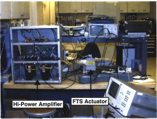
We have experimentally applied AFC to control a commercially available fast tool servo (FTS). This system, the Variform FTS, was designed and manufactured by Kinetic Ceramicsi and is shown in Figures 1-1 through 1-3. This particular FTS design consists of a tee-lever mechanism actuated by a double piezoelectric (PZ) stack arrangement coupled to two H-plate flexures, as illustrated in Figure 1-3. The
Figure 1-1: Variform FTS with hi-power amplifier and experimental hardware.
Icutting ToolI
Figure 1-3: (left): FTS actuator with one of the side plates removed, illustrating the
piezoelectric stacks. (right): FTS actuator with cutting tool attached to the tool
holder. Figures adapted from Kinetic Ceramics [73].
lever amplifies the displacement from the PZ stacks by a factor of 13:1 while the
flexures confine the action of the cutting tool to straight line motion. A high-power
amplifier with an on-board digital feedback controller, as shown in Figure 1-1, drives
the PZ stacks differentially to a maximum of ±400 V, which provides about a 200 Hz
0 dB crossover frequency with a total displacement of up to ±250 ptm (±0.010").
It is well known that piezoelectric materials are inherently non-linear with respect
to applied voltage. The Variform FTS controller takes advantage of an inner charge
loop to minimize the PZ hysteresis curve along with an outer position feedback loop.
During our experimental controller experiments, we utilized a PC-based digital
con-trol system. Therefore, we disabled the on-board concon-troller and implemented our
own control algorithms. A discussion of our implementation method is presented
in Section 3.2. We designed a preliminary controller, as described in Section 3.3,
and performed multiple closed-loop step responses where noticeable non-linear effects
were observed. We speculate that these results are due to the hysteresis curve of the
piezoelectric stacks. Thus, we re-enabled the inner charge loop, while bypassing the
Cos (
it
+Oi)
Cos WitxA
IP1 X (t)Xd(t)
r~t) + e (t)
+
u(t) + +
1t)
Y
1 b(t)
X
S
'
X
sin (coit
+
)
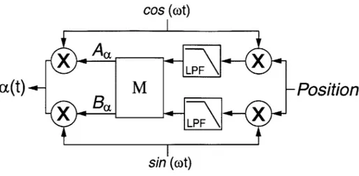
sin oit
Figure 1-4: Single resonator AFC control loop with the phase advance parameter 4 implemented. This system will exactly track or reject a signal with a single frequency
Wi.
designs (see Sections 3.4 and 3.5). The results of these experiments illustrate a signifi-cant attenuation of the non-linearities observed in Section 3.3. Finally, in Section 3.6, we performed several Adaptive Feedforward Cancellation experiments, which high-light the benefits of using AFC algorithms for reducing/eliminating the steady-state tracking errors of fast tool servos in high-precision diamond turning applications.
Figure 1-4 illustrates the loop configuration for a single resonator AFC controller, where P(s) is the transfer function of the plant being controlled. This closed-loop system is designed to provide zero steady-state error at the frequency wi. The internal dynamics of the AFC algorithm are linear time-varying (LTV) but in the literature it is shown that the input-output relationship from e(t) to u(t) is equivalent to a linear time-invariant (LTI) system [22]. The equivalent continuous-time transfer function is given by
s Cos Oi
+
Wi sin O;~Ci(s) =
[c i 2n] (1.1)Here gi is a proportional gain and
4,
is a phase advance parameter that can be chosen to improve the closed-loop system's robustness. This LTI equivalence is a very powerful result, since it enables us to use classical control techniques (i.e., Root Locusplots, Nyquist diagrams, Bode plots, gain and phase margins, etc.) to determine the
AFC system stability, robustness and performance characteristics.
In diamond turning applications, fast tool servos commonly follow near-periodic trajectories, since the tool motion is keyed to the fundamental spindle rotation fre-quency. The FTS axis can develop significant following errors, since conventional feedback loops only provide a finite controller gain. The FTS axis also experiences large disturbances (e.g., cutting forces and spindle imbalance) which usually occur at integer harmonics of the spindle rotation frequency. As a result of all these effects, the error signal primarily consists of a summation of sinusoids of known frequencies and unknown Fourier coefficients of the form
N
e(t) = Z[aicos(wit) + bisin(wit)]. (1.2)
n=1
In order to be able to provide zero steady-state tracking error to multiple harmonics, several AFC resonators can be placed in parallel to form a multiple resonator AFC system. The general form of a multi-resonator AFC controller is given by
N s cos qi + wi sin Oi
C(s) =2gi 2 (1.3)
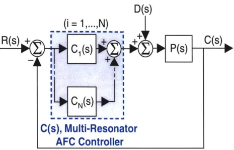
In our lab at the Massachusetts Institute of Technology, Marten F. Byl, Dr. Steven
J. Ludwick, and Professor David L. Trumper have developed a loop-shaping approach
to designing these multiple resonator AFC systems for use in diamond turning appli-cations [61. Their complete design, as shown in Figure 1-5, includes a conventional inner-loop controller Gc(s), command pre-shifting feedforward channel P*-l(jwi), and multiple resonator AFC controller C(s). The inner-loop is designed to maximize closed-loop bandwidth and provide a well characterized frequency response for de-signing the outer AFC loop. P*(s) still suffers from magnitude and phase shift as a function of frequency though. Therefore, they implement command pre-shifting
Command Pre-Shifting Feed-Forward Channel
P*d.jo
D(s)
R(s)
+++
C(s)
C,(s)
Gc(s)
P(s)
-P*(s),
Conventional Inner-Loop
CN
N(S)C(s), Multi-Resonator
AFC Controller
Figure 1-5: Control loop configuration used with the Variform FTS.
feedforward processing through the P*-(jwj) channel [6].
We use this loop-shaping approach and the controller configuration in Figure 1-5
to implement a ten resonator AFC system on the Variform FTS using a PC-based
digital control system, as presented in Section 3.6. Since we are designing this loop
for diamond turning applications, the trajectory reference signal contains integer
har-monics of the fundamental spindle rotation frequency, which can be described by a
Fourier series [1]. This means that the reference signal frequency components can be
determined a priori and an inverse model of P*(s) is only required for this discrete set
of frequencies. We can obtain the desired P*
1(s) magnitude and phase information
from an experimental frequency response of the inner-loop P*(jw), which we then use
to modify the feedforward command signal to the inner loop.
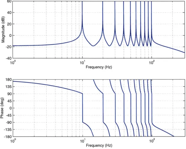
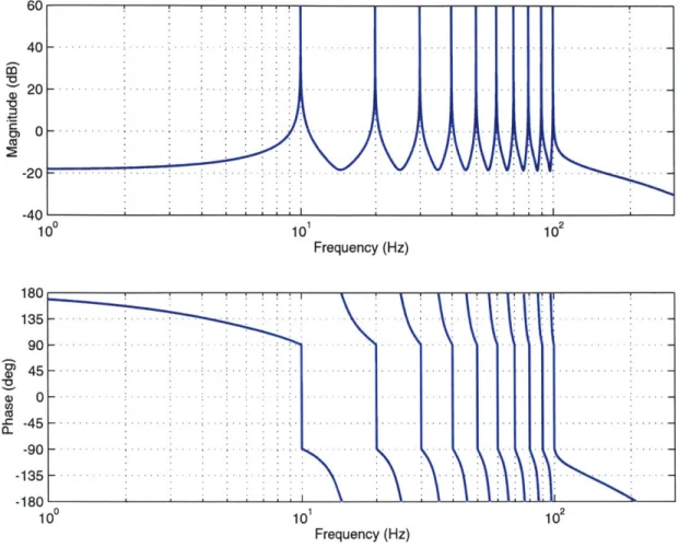
Figure 1-6 illustrates the calculated negative of the loop transmission frequency
response for the Variform FTS with a multi-resonator AFC controller and
conven-tional inner-loop integral compensator. The design of these loops is described in
detail in Chapter 3. For the present, we want to highlight the experimental results
60 40 20 0 -20 -40 1 180 135 90 45 0 -45 -90 -135 -180
0
10 110 2 Frequency (Hz) -. .. .-. -.. . --. -.- r .. -. -. .. .- . . .... ... . .... --. --. -. . . . .-. ..-. . - . . . . . . - -. -. -. -. ..-. .. -. . - - . . . -.. -. . . .- . .. - -. . . . .- -. . .. .- . -. .-. -.. -. . . . . .--.- -. .- -. -. - -...-..-100 10 1 Frequency (Hz) 102Figure 1-6: Calculated negative of the loop transmission frequency response for the
Variform FTS with a ten resonator AFC controller.
is designed to provide zero steady-state error to a signal with up to ten harmonics at
frequencies of
w = 10 Hz, 20 Hz, ..., and 100 Hz.
(1.4)
Figure 1-7 shows the experimentally measured ten-resonator AFC closed-loop system
frequency response with the addition of the experimental command pre-shifting
feed-forward loop. Note that the measured input-output transfer function passes through
0 dB and 00 of phase at each of the designed resonator frequencies, and thus that our
AFC design works well in practice. A small amount of magnitude and phase shifting
still exists at the in-between resonator frequencies, since the P*-
(jw)
magnitude
C
CU
a)
*0 -c
0.2 0 .1 6 -. - .- -.-.-.-.- .- .-0 .12 - - - - -.-.- -.- . S0.08 - - -- ---- --S 0 .0 4 .. . . . .- . ... .. .... - ... . . -. ... . -. -.-.-.-. ... . -0.04 -2 -0.08 - - - - -.-.-.--0 .12 - - - - .- . -0 .1 6 -.-.-.-.- -.-.--0.2 100 101 102 Frequency (Hz) 0 -1 -4 --.-. -a. - -, -31 -7 100 101 102 Frequency (Hz)
Figure 1-7: Experimental FTS closed-loop frequency response from reference to
out-put with a ten resonator AFC controller and command pre-shifting feedforward
chan-nel.
and phase data is not 100% accurate relative to the actual system. However, up
to approximately 100 Hz, the experimental results only show about a maximum 2%
deviation from the 0 dB line in the Blot magnitude plot and 2' of phase lag.
Figure 1-8 shows the experimental Variform FTS closed-loop error signal during an
air-cutting experiment with and without AFC control. The peak-to-peak system error
without Adaptive Feedforward Cancellation, measured with the Variform FTS LVDT
feedback sensor, amounts to approximately 15% of the trajectory reference signal,
while the peak-to-peak system error with AFC control reduces to about 0.5%. It
Trajectory Reference Signal -. -. -. - -. . . . . .-. -. -. - . .. .-.-.-.- . .. . .. . . .. .. . . --. .. -. ..-- -. -. . . .. -. -. -. ..-. . . . . . . .. ..-. . . ..-. . .. .-. . -. -..- . . . .- . . . . . . . . . . . .-.. .-.. -... -... .... -... .... 0 0.1 0.2 0.3 0.4 0.5 0.6 0.7
Error Signal without 10 Resonator AFC Controller
0.8 0.9 1
) 0.1 0.2 0.3 0.4 0.5 0.6 0.7 0.8 0.9 1
Error Signal with 10 Resonator AFC Controller
0.1 0.2 0.3 0.4 0.5
Time (sec)
Figure 1-8: Comparison of the experimental closed-loop
AFC Control.
0.6 0.7 0.8 0.9 1
error signal with and without
66 E 45 22 0) E 0 a -22 -l 45 0 E C.) C5 13 9 4 0 -4 -9 -13 0.4 - . . . . .. . . . . . .. . .. . .. . . ..-.. -.. -.. -.. - - ... .-. --. -. .. . . . ... -. .. . . . .... .-.. .- --.. . .- . ..--.. . .. . -- -.. . . ..-.. -. . . .-. --. --. . . . . .-.-.-.-. .-.-.-.- . -0.2 E 0 0 -0.2 -0.4 0 . . . . . . ! ..
- -
-.
-
-
.-
-
-
-
-
-
-
-
- -
-
-
-
...--I
0.07 0.0 0.02 C ,-0.02 ,--0.0 -n0n7 5 5 -. .. .. .. .. .. ..-.-.-.. - S im ulated . -.-. Experimental 5 - . . . .- . . . .. . . ..-. .. -. .. . -. . .- -- - .- -0 5
5
... ...
... ...
0 0.125 0.25 0.375 0.5 0.625 0.75 0.875 1 1.125 1.25 1.375 1.5 Time (sec)Figure 1-9: Experimental and simulated transient responses of a single resonator AFC
system designed to follow a reference signal with
wi =
50 Hz.
should also be noted that the error signal with AFC control is dominated by the noise
of the LVDT and there appears to be no apparent signal left that is correlated to the
input reference signal. Therefore, the steady-state tracking error is essentially zero.
Due to time and computer memory constraints, we were not able to implement the
command pre-shifting channel during this particular test. Then again, we would have
had trouble noticing any further improvements in the closed-loop response, since the
addition of just the AFC controller apparently reduced the steady-state tracking error
to less than the noise of the LVDT. These results illustrate a dramatic improvement in
the FTS's steady-state tracking performance to constant amplitude periodic signals.
However, determination of the convergence rate of the closed-loop system to changes
in the reference or disturbance amplitude is not an obvious output of these analyses.
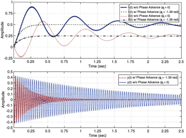
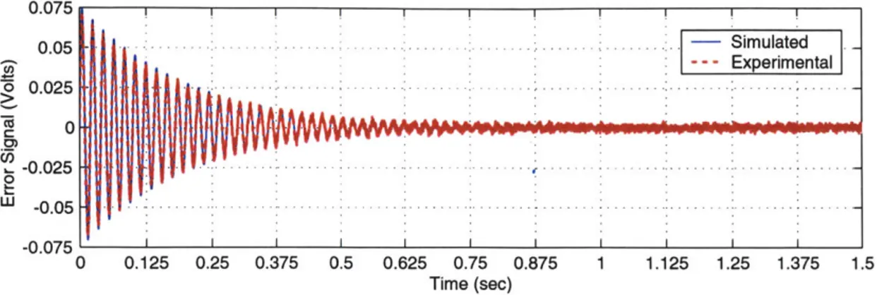
Figure 1-9 compares the simulated and experimental transient responses of a
sin-gle resonator AFC closed-loop system designed to follow a signal at
wi =
50 Hz. This
system provides approximately zero steady-state tracking error (if we ignore the noise
of the LVDT sensor) but the amplitude of the error signal exhibits an exponential
convergence rate. Hall and Wereley [53] and Bayard [64] state that this rate is
approx-imately equal to the real part of the least damped closed-loop poles. These results
con-stant amplitude reference or disturbance signal, but they do not provide an intuitive measure of the amplitude dynamics of an Adaptive Feedforward Cancellation system to sinusoids with slowly time-varying amplitudes or frequencies.
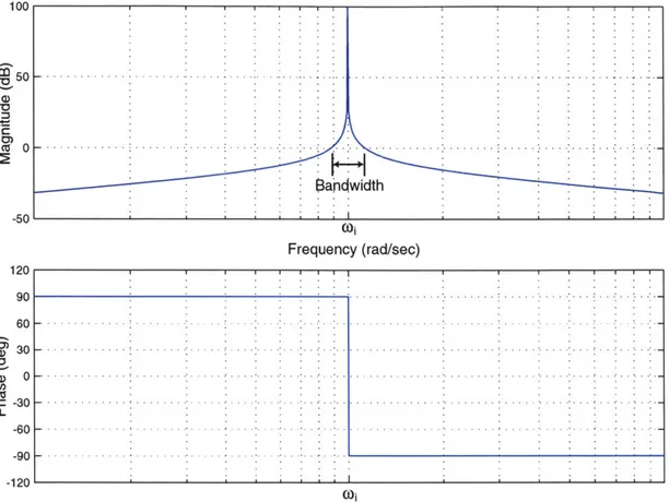
Roberge [46] showed that the amplitude of a sinusoidal oscillator can be stabi-lized by using an auxiliary feedback loop. He refers to this approach as an oscillator amplitude control system and states that if the bandwidth of this loop is much lower than the frequency of oscillation, then we can analyze the amplitude dynamics alone and ignore the sinusoidal portion of the loop. We provide a detailed discussion of Roberge's oscillator amplitude control system in Chapter 4 and use his work to sim-plify the single resonator AFC controller into a combination of oscillator amplitude control systems.
Chapter 5 describes our method of viewing Adaptive Feedforward Cancellation from an oscillator amplitude control (OAC) perspective, which provides an approxi-mate measure of the amplitude dynamics of the closed-loop system. This perspective also allows the additional use of classical control techniques to determine an AFC loop's stability, convergence, and robustness properties. Our work builds upon that of Sacks et al [22], Hall and Wereley [53], and Tamisier et al [35]. We use an averaging analysis to simplify the single resonator AFC system from Figure 1-4 into two coupled single-input single-output (SISO) amplitude control loops and show that by setting the phase advance parameter
#i
equal to the phase of the inner closed-loop P*(s) at the resonator frequency wi, the loops are effectively de-coupled. This simplification is detailed in Section 5.4. An illustration of the single resonator AFC system viewed from an OAC perspective is shown in Figure 1-10, where aREF, bREF, aDIST, andbDIST refer to the input amplitudes of the periodic reference and disturbance signals and Ia(t) and XI'b(t) equal the output amplitude envelopes of the cosine and sine
channels of the single resonator AFC system.
aDIST
REF(t) 1 (t) + a P(s) IP(j+)I -0Va(t)
1cos,
sin+ Output Signal
bRE -sinO, cose 1
+
~
)lPj,1
En
veloes
-ib(t) b(t) _ bAMP(t)
Coupling Matrix
R(0,)
bDSFigure 1-10: Closed-loop block diagram for the single resonator AFC system viewed
as a multiple-input multiple-output (MIMO) oscillator amplitude control system.
oscillator amplitude control perspective enables the use of classical control techniques
to approximate the dynamics of the AFC closed-loop system due to changes in the
amplitude of the reference or disturbance signal. When </i
=
ZP(jwi), the coupling
matrix in Figure 1-10 is diagonalized, which produces individual amplitude control
loops for the sine and cosine channels of the single resonator AFC system. These
loops effectively have the same dynamics (or an equivalent loop transmission) and
the dominant OAC closed-loop pole approximates the amplitude dynamics of the
AFC system output.
Figure 1-11 illustrates the closed-loop transient response of a single resonator AFC
system designed to cancel a constant amplitude disturbance signal at wi
=
180 rad/sec.
This figure compares the predicted AFC error signal to the approximate output using
our oscillator amplitude control perspective. We see that since certain requirements
are met, as discussed in Section 5.3, the OAC perspective predicts the response of the
actual AFC system quite well. The approximate amplitude error envelope
eAMP(t),which is determined by the location of the dominant oscillator amplitude closed-loop
pole, also predicts the convergence rate with and without the addition of the phase
parison of the ErrorSignal e(t)using AFC and OAC without the Phase Advance Parameter (#i= 0) E E 0.25 0.5 0.75 1 1.25 Time (sec) 1.5 1.75 2 2.25 2.5
Figure 1-11: Simulated transient response of a single resonator AFC system designed
to cancel a constant amplitude disturbance with
wi =
180 rad/sec. Included are
the actual AFC system error signal, the approximate error signal using our OAC
perspective, and the approximate amplitude error envelope, which is determined by
the dominant oscillator amplitude closed-loop pole.
When the phase advance parameter is chosen properly, we can use the resulting
negative of the loop transmission of the equivalent OAC loops to determine the
sta-bility and convergence properties of the single resonator AFC system. Also, when
#i
=
ZP(jwi), the sine and cosine channels of the single resonator system both have
90' of phase margin and are robust to modelling errors in the plant transfer function.
As long as any unmodelled plant dynamics do not contribute more than t900 of
additional phase lag to the negative of the loop transmission, the closed-loop system
is stable but the convergence time increases and the AFC sine and cosine channels
Com 0.6 0.4 0.21 0 -0.2 -0.4 -AFC .- - -.-.- OAC----Amplitude Error Envelope: eAM
. . .- -. -. . . . . . ..-.
-. -. -.-. . ... .. . ..-- -.-.-.- -.-.
0 0.25 0.5 0.75 1 1.25 1.5 1.75 2 2.25 2.
Time (sec)
Comparison of Error Signal e(t) using AFC and OAC with the Phase Advance Parameter (4i =LP(jOi))
6
-- AFC
4 --. -..-.---.-..- .. . . . . .. . . . .. . . . . -. - - - O A C ----Amplitude Error Envelope: eAPt 2 -..-- -. -. -.-- .- -. 0-2 -. .--. .--. .- -. 4. ' -. . . . .. -. .. . . . ... . . ... . . .. . . . ..-. ..-. .. -. .. .-.. -A 5 0. 0. 0. -0. -0. -0. 0 _V.
![Figure 1-12: HHC closed-loop block diagram. Figure adapted from Hall and Were- Were-ley [53].](https://thumb-eu.123doks.com/thumbv2/123doknet/13859474.445373/42.918.230.683.120.511/figure-hhc-closed-block-diagram-figure-adapted-hall.webp)