Aerothermodynamics and Operation of Turbine
System under Unsteady Pulsating Flow
MASSACHUSETTS INSTITUTE OF TECHNOLOLGY byJinwook Lee
JUN 23 2015
B.S., Seoul National University (2013) LIBRARIES
Submitted to the Department of Aeronautics and Astronautics in partial fulfillment of the requirements for the degree of
Master of Science in Aeronautics and Astronautics at the
MASSACHUSETTS INSTITUTE OF TECHNOLOGY
June 2015
®
Massachusetts Institute of Technology 2015. All rights reserved.Signature redacted
A u th o r ...
Certified by
Denartment of Aeronautics and Astronautics
Signature redacted
May 15, 2015...
Choon S. Tan
Signature redacted
C ertified by . ...
Senior Research Engineer Thesis Supervisor
Borislav T. Sirakov Manager, Aerodynamics Science, W&A COE Honeywell Turbo Technologies Thesis Supervisor
Signature redacted
Accepted by ... ....
Paulo C. Lozano
Associate Professor of Aeronautics and Astronautics Chair, Graduate Program Committee
Aerothermodynamics and Operation of Turbine System under
Unsteady Pulsating Flow
by
Jinwook Lee
Submitted to the Department of Aeronautics and Astronautics on May 15, 2015, in partial fulfillment of the
requirements for the degree of
Master of Science in Aeronautics and Astronautics
Abstract
An assessment of a turbine system operating under highly pulsating flow environment typically found in vehicular turbochargers is made to: identify the key operating parameters, enable the formulation of a reduced order model, delineate the sources of loss and suggest strategies for performance improvement. The turbine system consists of a scroll-volute followed by a turbine wheel and then a diffuser. The assessment includes calculating unsteady three-dimensional flow in the turbine system followed by in-depth interrogation complemented with flow modeling. The key findings are (1) The flow mechanisms behind the turbine wheel performance, the diffuser loss and the wastegate port loss appear locally quasi-steady such that we can characterize the performance of the components based on a series of steady calculations subjected to varying inlet conditions reflecting the inlet flow pulsation; (2) the operation of scroll-volute and the diffuser pressure recovery can be adequately determined using a quasi-one-dimensional unsteady flow model; (3) A significant fraction of the loss that is not from skin frictions occurs downstream of turbine wheel exit (18%pts out of 34%pts in Peak Torque and 20%pts out of 56%pts in Turbo Initial Transient based on cycle loss debit); (4) The condition of maximum power extraction on unsteady pulsating environment can be approximated with a simple modeling of volute storage effect. A physically consistent definition of ideal power that elucidates the role of unsteadiness in an unsteady turbine system is derived; it informs one on what the extractable power is compared to what it could be for an ideal system. Finally the findings are used to define the required attributes of methodology for estimating efficiency with a specified uncertainty bandwidth.
Thesis Supervisor: Choon S. Tan Title: Senior Research Engineer
Thesis Supervisor: Borislav T. Sirakov
Acknowledgments
First and foremost, I would like to sincerely thank my advisor, Dr. Choon S. Tan, for all his patience, guidance, and enlightening insight throughout my research and learning at MIT. I can assert, without any hesitance, that I would have achieved literally nothing at MIT without him. I also would like to thank Professor Edward M. Greitzer for being a friendly consultant from time to time through my experience at Gas Turbine Laboratory.
And, I thank Samsung Foundation of Culture and Honeywell Turbo Technology for their merciful support over my research. I especially thank Dr. Borislav T. Sirakov and Dr. Hong-Sik Im from Honeywell Turbo Technology for their critical advice and affection on my research.
Also, I will never forget all my GTL friends! Especially, I would like to thank, once again, our forever-admin (eventually to be Dr.) Andras L. Kiss for his noble sacrifice to resurrect GTL cluster from ashes from time to time. No one can dare to dispute that GTL without him would have been definitely fruitless.
And, I cannot skip this person. Changhoon Oh. I thank him so much for being a constant friend whom I can bother at any moment without worrying that the person might kill me in return. I was fortunate enough to have him as a next-door neighbor in building 31.
Actually, there is one more person. Hyosang Yoon. I am so glad that I have such a great friend like him in AeroAstro. He was always the first one to come to me whenever I was struggling with so many hardships. I really appreciate his help and advice.
Finally, I deeply appreciate all my family - mom, dad, and my brother Sungwook - for their ever lasting love and patience. I can hardly imagine that I could have ever initiated this long journey to this foreign country without their endless support.
Contents
1 Introduction 23 1.1 M otivation . . . . 23 1.2 Technical Background . . . . 24 1.2.1 Turbocharger . . . . 24 1.2.2 Sources of Unsteadiness . . . . 26 1.2.3 Characterization of Unsteadiness . . . . 271.2.4 Turbocharger versus Pulse Detonation Engine . . . . 29
1.3 Literature Review . . . . 30
1.3.1 Metric for Unsteady Turbine System Performance . . . . 30
1.3.2 Timescale Analysis and Impact of Unsteadiness . . . . 31
1.3.3 Modeling of Turbine under Unsteady Pulsating Flow . . . . . 31
1.3.4 Flow Management Strategy . . . . 32
1.4 Research Questions and Objectives . . . . 32
1.4.1 Research Questions . . . . 32
1.4.2 Research Objectives . . . . 34
1.5 Summary of Key Results and Contributions . . . . 35
1.6 Organization of Thesis . . . . 36
2 Technical Approach 39 2.1 A nalysis . . . . 40
2.1.1 Temporal Discretization of Inlet Pulsation . . . . 40
2.1.2 Categorization of Sub-Components . . . . 41
2.2 Synthesis . . . . 2.2.1 Integrating components into system . . . . 2.2.2 Flow Management Strategy . . . . 2.2.3 Maximum Power Extraction Condition . . 2.3 Technical Details in Implementations . . . . 2.3.1 CFD Simulation Specifications . . . . 2.3.2 Metric for Unsteady System Performance . 2.4 Sum m ary . . . . 3 Metric for Unsteady System Performance
3.1 Review of Steady Ideal Power . . . . 3.2 Derivation of Quantitative Expression for Unsteady Ideal Power . . . 3.2.1 Storage Rate Effect in Unsteady Flow System . . . . 3.2.2 Entropy Generation Rate and Loss . . . . 3.2.3 Approximation of Entropy Generation Term in the Expression for Ideal Power . . . . 3.3 A pplication . . . . 3.3.1 Metric for the Utility of Component Models . . . . 3.3.2 E fficiency . . . . 3.3.3 Loss Categorization . . . . 3.4 Sum m ary . . . . 4 Component Models
4.1 Categorization of Component Models . . . . 4.2 Quasi-steady Component Models . . . . 4.2.1 Wastegate Port Loss Model . . . . 4.2.2 Turbine Wheel Performance Model . . . . 4.2.3 Diffuser Loss Model . . . . 4.3 Unsteady Component Models . . . . 4.3.1 Volute M odel . . . . 4.3.2 D iffuser M odel . . . . . . . . 42 . . . . 42 . . . . 43 . . . . 43 . . . . 43 . . . . 43 . . . . 47 . . . . 47 49 49 51 53 54 56 57 57 58 58 59 61 61 62 63 65 67 71 72 81
4.3.3 Radial Scroll Interaction Model . 4.4 Interface Models . . . .
4.4.1 Volute to Turbine Interface Model . . . 4.4.2 Turbine to Diffuser Interface Model . . 4.5 Error from Locally Quasi-Steady Assumption
4.5.1 Assumption Error . . . . 4.5.2 Interpolation Error . . . . 4.5.3 Normalized Interpolation Error . . . . 4.6 Sum m ary . . . . . . . . 8 2 . . . . 8 4 . . . . 8 5 . . . . 8 6 . . . . 8 6 . . . . 8 7 . . . . 8 8 . . . . 8 9 . . . . 9 1
5 Loss Mechanisms and Potential for Improvement 5.1 Procedure ... ...
5.1.1 Component Model Based Loss Mechanism Identification 5.1.2 Boundary Layer Loss Estimation . . . . 5.1.3 Tip leakage flow estimation . . . . 5.2 Loss Categorization for Peak Torque and Turbo Initial Transient
eration . . . . 5.2.1 Peak Torque . . . . 5.2.2 Turbo Initial Transient . . . . 5.3 Flow management for radial scroll interaction . . . . 5.4 Flow management for turbine wheel inflow angle mismatch . . . 5.4.1 General Description . . . . 5.4.2 Ideal Variable Inlet Guide Vanes . . . . 5.5 Sum m ary . . . . Op-93 93 94 95 95 96 96 96 97 99 100 101 101
6 Maximum Power Extraction Condition and Proposed Multi-Tiered
CFD Approach 105
6.1 Maximum Power Extraction Condition . . . . 105
6.2 Multi-Tiered CFD Approach . . . . 108
6.2.1 Full Unsteady CFD . . . . 108
6.2.3 QS (Quasi-Steady) Approach . . . . 6.2.4 Single Steady CFD at Maximum Power Extraction Condition 6.3 Limitations in Steady CFD Results . . . . .
6.4 Guideline for Selecting a Specific Approach . 6.5 Sum m ary . . . .
7 Summary and Future Work
7.1 Summary . . . . 7.2 Key findings . . . . 7.3 Recommendation for Future Work
A Frozen Rotor Interface
B Volute Inlet Mass Flow Fluctuation
. . . . 112 . . . . 113 115 119 . . . . 119 . . . . 120 121 123 127 109 109
List of Figures
1-1 2010 BMW 4.4 L Gasoline Wastegate Twinscroll Turbocharger . . . . 25
1-2 Twinscroll Type Turbocharger . . . . 26
2-1 Outline of the research . . . . 39
2-2 Inlet Pressure Ratio Boundary Condition . . . . 41
2-3 A Set of Steady Inlet Conditions Encompassing the Locus of Unsteady Inlet Condition . . . . 42
2-4 Conceptual view . . . . 44
2-5 Turbine System Overview . . . . 45
2-6 Turbine System Configuration . . . . 46
4-1 Categorization of Component Models . . . . 62
4-2 Wastegate port loss characterization . . . . 64
4-3 Comparion of wastegate port loss model and unsteady CFD result . . 65
4-4 Turbine inflow angles . . . . 66
4-5 Inflow Angle Parameter Space . . . . 68
4-6 Comparion of turbine wheel performance model and unsteady CFD resu lt . . . . 69
4-7 System Instantaneous Efficiency . . . . 70
4-8 Diffuser mixing loss modeling . . . . 71
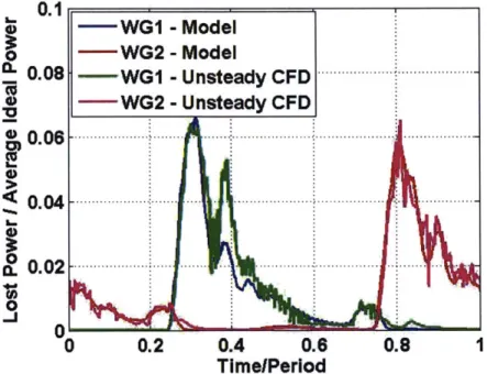
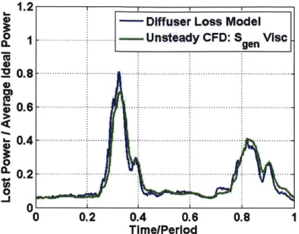
4-9 Comparion of diffuser loss model and unsteady CFD result . . . . 72
4-10 Volute modeling . . . . 73
4-11 Quasi-1D Volute Model: Inlet 1 - Part 1/3 . . . . 75
4-12 Quasi-1D Volute Model: Inlet 1 - Part 2/3 . . . . 76
4-13 Quasi-1D Volute Model: Inlet 1 - Part 2/3 . . . . 77
4-14 Quasi-iD Volute Model: Inlet 2 - Part 1/3 . . . . 78
4-15 Quasi-iD Volute Model: Inlet 2 - Part 2/3 . . . . 79
4-16 Quasi-1D Volute Model: Inlet 2 - Part 3/3 . . . . 80
4-17 Diffuser mixing modeling . . . . 81
4-18 Diffuser mixing modeling. Region of consideration . . . . 83
4-19 Quasi-1D Diffuser Model . . . . 84
4-20 Radial scroll interaction from inlet 1 side scroll to Inlet 2 side scroll . 85 4-21 Radial scroll interaction from inlet 1 side scroll to Inlet 2 side scroll -datum locations . . . . 86
4-22 Comparison of radial scroll interaction model and unsteady CFD result 87 4-23 Steady Cases Encompassing Unsteady Case . . . . 89
4-24 Normalized Interpolation Resolution . . . . 90
4-25 Reduced number of steady cases . . . . 91
4-26 Comparion of turbine wheel performance model and unsteady CFD resu lt . . . . 92
4-27 Comparion of turbine wheel performance model and unsteady CFD resu lt . . . . 92
5-1 Boundary Layer Loss Model in Volute . . . . 95
5-2 Cycle Loss Breakdown - Peak Torque . . . . 97
5-3 Cycle Loss Breakdown - Turbo Initial Transient . . . . 98
5-4 Measurement of radial scroll interaction from unsteady CFD on Turbo Initial Transient operation . . . . 99
5-5 Leakage flow from inlet 2 side to inlet 1 side driven by a higher static pressure side due to the configuration of the radial scroll . . . . 100
5-6 A suggestion on the radial scroll configuration for the reduction of radial scroll interaction . . . 101
5-7 Velocity triangle at peak power extraction point on two different oper-ation s . . . . 102
5-8 Locus of Power vs Turbine Instantaneous Efficiency on Two Scenarios 103
5-9 Conceptual Ideal IGV Implementation . . . . 103
6-1 Quasi-1D Diffuser Model . . . . 106
6-2 Power scaling . . . . 108
6-3 Comparison between Unsteady CFD and QS Approach based on Tur-bine Perform ance . . . . 116
6-4 Comparison between Unsteady CFD and QS Approach at Volute Inlet 117 A-1 Turbine Inlet Interface Environment . . . 124
A-2 Comparison of Frozen Rotor Interface and Rotating Impeller Interface 125 A-3 FFT of the Difference between the Two Interfaces . . . 125
B-1 Volute Inlet Mass Flow Fluctuation, Peak Torque Operation . . . 128
B-2 Volute Inlet Mass Flow Fluctuation, Turbo Initial Transient Operation 129 B-3 Inlet Mass Flow Fluctuation . . . 130
B-4 Decoupled Volute Model . . . 131
B-5 Impact of Area Ratio . . . 131
List of Tables
6.1 Comparison of Turbine Flow Environment between Unsteady CFD and Single Steady CFD - MPE on Inlet 1 side pulse, Peak Torque . . . . . 111 6.2 Comparison of Turbine Flow Environment between Unsteady CFD and
Single Steady CFD - MPE on Inlet 2 side pulse, Peak Torque. . . . . 111 6.3 Comparison of Turbine Flow Environment between Unsteady CFD and
Single Steady CFD - MPE on Inlet 1 side pulse, Turbo Initial Transient 112 6.4 Comparison of Turbine Flow Environment between Unsteady CFD and
Single Steady CFD - MPE on Inlet 2 side pulse, Turbo Initial Transient 112 6.5 Comparison of Loss Categorization Result between Unsteady CFD and
Single Steady CFD - Cycle Averaged Quantity, Peak Torque . . . . . 113 6.6 Comparison of Loss Categorization Result between Unsteady CFD and
Single Steady CFD - Cycle Averaged Quantity, Turbo Initial Transient 113 6.7 Comparison of Loss Categorization Result between Unsteady CFD and
Single Steady CFD - Ideal Work Weighted Cycle Average Quantity, Peak Torque . . . . 114 6.8 Comparison of Loss Categorization Result between Unsteady CFD and
Single Steady CFD - Ideal Work Weighted Cycle Average Quantity, Turbo Initial Transient . . . . 114
Nomenclature
/tub Turbine inflow incidence angle
6m Rankine vortex core radius at mixed out state
rh Mass flow rate
g"e' Volumetric entropy generation rate
Ster
Volumetric thermal entropy generation rateS'iSC Volumetric viscous entropy generation rate
SBL Entropy generation rate from boundary layer dissipation
Sge,i Entropy generation rate from ith mechanism Sref Reference entropy generation rate
SRSI,12 Entropy generation rate due to radial scroll interaction from inlet 1 side to
inlet 2 side
SRSI,21 Entropy generation rate due to radial scroll interaction from inlet 2 side to
inlet 1 side W Power
r Isentropic efficiency -y Specific heat ratio
'tturb Turbine inflow axial angle
E
Non-dimensional energy storage rateI Non-dimensional mass storage rate
S Non-dimensional entropy storage rate
Qm Rankine vortex core angular speed at mixed out state
(
)
Time averaged quantitym Mass averaged quantity
( )
Mixing averaged quantity b Any flow variablep Static density
pt Stagnation density
T Shear stress tensor
0 Cylindrical circumferential coordinate
O Momentum thickness
(
) Vector quantity u VelocityA Area
a Acoustic speed
Am Diffuser mixed out state area
Cd Boundary layer dissipation coefficient
Dtrb Turbine outer diameter
E Quasi-iD Euler equation component matrix
e Specific energy
et Specific stagnation energy
Ext Quasi-1D Euler equation extraction matrix H Quasi-1D Euler equation component matrix h Specific enthalpy
ht Specific stagnation enthalpy
in Inlet inj Injection
K12 Proportional constant for radial scroll interaction from inlet 1 side to inlet 2 side
K21 Proportional constant for radial scroll interaction from inlet 2 side to inlet 1 side
Keff Effective pressure recovery coefficient for diffuse model
keff Effective thermal conductivity
L Length scale out Outlet
p Static pressure
pa Atmospheric pressure
pt Stagnation pressure
peff Effective static pressure on diffuser side wall
R Air specific gas constant r Cylindrical radial coordinate r1 Inlet 1 pressure ratio
r2 Inlet 2 pressure ratio
Rm Diffuser mixed out state effective radius Re Reynolds number
ref Reference state
S Quasi-1D Euler equation area distribution
s Specific entropy s Streamline coordinate T Static temperature
t Time
T Stagnation temperature
Tperiod Period of pulsation
tre, Flow residence time
Trise Pulse rise time
turbln Turbine inlet turbOut Turbine outlet
U Velocity scale
U, ith Cartesian velocity component
u2 1 Characteristic velocity for radial scroll interaction from inlet 2 side to inlet 1 side
Uturb Turbine blade tip speed
V Velocity in absolute frame V Volume
W Velocity in relative frame
w Specific work
x 1-dimensional coordinate
xj jth Cartesian coordinate z Axial coordinate
Nature does not hesitate.
1
'From an everyday conversation with Changhoon Oh, a next-door neighbor in Sloan Automotive Laboratory.
Chapter 1
Introduction
1.1
Motivation
Unlike conventional turbomachineries, turbine stages for turbochargers and pulse det-onation engines operate under time-varying inlet condition. The pulsating boundary condition for both power extracting devices, originates from the inherent unsteadiness of the energy source in the combustion stage: the reciprocating motion of cylinders from the internal combustion engine for the turbocharger, and the periodically sched-uled detonations in a cyclic array of tubes with explosives for the pulse detonation en-gine. Due to the unique unsteady boundary condition, the flow environment through the turbine system -turbine wheel and the components in the immediate vicinity (i.e. volute, wastegate, diffuser, etc.) - are changing with time continuously in a pulsating manner. Therefore, the technical approach and the underlying philosophy for the design of the turbine system can be distinctly different and thus must be adapted accordingly.
However, a direct 3D unsteady computational approach targeted to understand the aforementioned unsteady effect typically suffers from two major difficulties: (1) high computational cost, (2) ineffective assessment of the result.1 Firstly, the
cal-culation time for unsteady simulation can easily surpass the steady case by a few 'The unsteady experiment also, of course, involves technical challenges such as the requirement of high temporal resolution sensors, synchronization between apparatus and the corresponding ad-ditional expenditure. However, this thesis will focus on the computational aspects of the problem.
order of magnitude. Also, even if the numerical results are available, it may not be a direct task to extract the essence of the flow physics underpinning the turbine system unsteady operation.
The overall goal of the thesis is thus to formulate a simplified reduced-order frame-work to assess the turbine system performance
/operation
under pulsating environ-ment. During the course of the work, physically consistent definition of ideal power extractable from an unsteady system is derived and elaborated upon. By assessing the difference between the ideal power and the real power, the potential for improvement from the current system performance is quantified.1.2
Technical Background
The focus of this thesis is on a representative turbine stage for vehicular turbochargers. As such, we will first elaborate on the engineering and the technical aspects of a representative turbocharger followed by a brief description of pulse detonation engine for comparison (with vehicular turbocharger engine).
1.2.1
Turbocharger
In essence, the turbocharger (see Figure 1-1) is a gas turbine with a typical compressor-combustor-turbine configuration where combustion process is replaced by an internal combustion engine. The role of turbocharger is to extract the otherwise wasted avail-able energy from the main engine exhaust through a turbine and feed it back into the combustion process in terms of the pressurized air via a compressor.
The benefit from the use of turbocharger is realized effectively through engine downsizing. Compared to a naturally aspirated engine (without turbocharger) which takes air from atmospheric pressure, a turbocharged engine can be smaller in size since the intake air is pressurized (the air can accommodate the same mass of oxygen required in a smaller volume). Pressurizing air leads to improved fuel economy via reduced mechanical losses from engine downsizing. Further explanation with in-depth
Figure 1-1: 2010 BMW 4.4 L Gasoline Wastegate Twinscroll Turbocharger [1] - Note that the twinscroll turbine (left) is axially connected with the compressor (right). The internal combustion engine (connected through volutes) is not shown on the figure
assessment of the matching of turbocharger to reciprocating internal combustion en-gine can be found in [2].
Specifically, twin scroll type turbine stage (see Figure 1-2) is considered in the thesis. A twin scroll type turbine stage is a radial turbine stage with a volute that keeps the inlet flow separated in two parallel channels until it reaches the volute exit/discharge plane near the turbine wheel. The purpose of the volute is to take the inlet flow from a pipe and distribute it circumferentially onto the turbine wheel. In essence the twin scroll volute has two separate sub-volutes that discharge the flow into a common flow path upstream of the radial turbine wheel. The flow coming from the engine is kept separated in two channels for as far as possible downstream in order to preserve the energy produced by the operating engine cylinders (so as to avoid mixing between the high energy flow in the channels linked to the engine valves that are opening, with the dead flow in the channels linked to the valves that are closed at that moment of time). Each parallel sub-volute is connected directly to one half of the engine cylinders (for example each sub-volute is connected to two cylinders on a four cylinder engine).
A challenging aspect of the twin scroll type turbine is the twin scroll interaction.
Since one scroll is not operating (under low stagnation pressure) while the other scroll is operating (under high stagnation pressure), the interaction of the two scrolls cannot be avoided; that is, some of the high pressure side scroll flow leaks through the other scroll with a negative impact on the turbine wheel performance. As such, the natural questions to ask is whether there is a significant loss arising from twin scroll interaction and, if there is, how we can mitigate it.
Figure 1-2: Twinscroll Type Turbocharger [1] - A cross section of the twin scroll is
shown with the turbine wheel. The compressor wheel is on the opposite side.
1.2.2 Sources of Unsteadiness
The sources of unsteadiness for turbocharger turbine stage can be categorized as
follows:
1. Engine operation change timescale (~0. 1 - 1Hz):
The timescale of the change in internal combustion engine operation due to any changes in load or speed. It impacts the characteristics of the pulsation at inlet (period, amplitude, pulse shape, etc.)
2. Inlet pulsation timescale (~10 - 100Hz):
The timescale associated with the inlet pulsation in stagnation pressure and stagnation temperature
3. Blade pass timescale (~100 -1000Hz):
The timescale for a blade to travel through one blade pitch, the circumferential distance between adjacent blades
Firstly, engine operation change can be treated on a quasi-steady basis without any problem since it involves a sufficiently long timescale compared to the flow resi-dence time through the turbine system. For the flow situations encountered here, the unsteady effects associated with the rotating blade appears to be small compared to that associated with the inlet pulsation; the rational for this is given in the analysis presented in Appendix A.
By contrast, the level of impact of the unsteadiness from the inlet pulsation which drives the system performance pulsation has to be assessed quantitatively. This as-sessment thus constitutes an important aspect of this thesis.
1.2.3
Characterization of Unsteadiness
Basic physical laws governing fluid flow (mass conservation, Newton's second law, first/second law of thermodynamics) can generally be expressed as:
-
(1.1)
Ot
where b can be any of the flow variable (p, pa, pet, ps) pertaining to the corresponding physical law. The physical laws as expressed in equation (1.1) allow one to know what happens to the infinitesimal fluid particle that is convecting with the local flow velocity. If the system of interest is approaching the steady state, the impact from the first term in (1.1) reduces relative to the second term. As such, the ratio of the first term (temporal term) to the second term (convective term) provides a measure on the relative importance of unsteadiness. It is called reduced frequency
[3]:
Temporal term L/U (1.2) Convective term At
where L, U, and At correspond to characteristic length, characteristic velocity and characteristic time respectively for the problem of interest. Thus, reduced frequency can be interpreted as the flow residence time through the system over the unsteadiness time scale. As it becomes larger compared to unity, the unsteadiness starts to play an important role and vice versa.
For the case of turbocharger, the engine operation is such that it has a reduced frequency of order of 0.1 or less and thus can be treated in a quasi-steady manner as previously noted. However inlet pulsation has a reduced frequency of order of 1 or greater so that it is important to assess if the flow unsteadiness needs to be fully accounted for. Here the characteristic time is chosen as the pulse rise time from the given inlet pulsation since that is the time scale of significant change in the system behavior.
A similar quantity is the compactness set by the time scale characterizing acoustic propagation. For low Mach number flow (as is in the volute initial region, M < 0.3), compactness scales as:
Compactness- 1 L/a (1.3)
At
where L, a, and At correspond to characteristic length, characteristic acoustic speed and characteristic time respectively for the problem of interest. As such, the com-pactness is the ratio of unsteady time scale (the inlet pulse rise time) to the time for the acoustic wave to propagate through the device. For the turbocharger volute con-sidered in the thesis, 1/compactness is around 0.5 implying that the acoustic speed driven pressure wave effect would not be significant. As will be seen in Chapter 4, the compactness effect is reflected as an almost quasi-steady behavior of stagnation pressure through volute (spatially constant through volute on each time step).
1.2.4
Turbocharger versus Pulse Detonation Engine
The environment for turbine system operation on turbocharger is similar to the case of pulse detonation engine (PDE). For both of the cases, the turbine wheel experi-ences unsteady pulsating flow; thus, the flow phenomenon through entire system is inherently unsteady. In this section, we compare the two situations so as to determine if the results from the current research on turbocharger are equally applicable to the situation of pulse detonation engine.
Pulse Detonation Engine
PDE has long been investigated as a potential game-changer in air-breathing propul-sion. There are two major traits: (1) Despite its simplicity, PDE can operate through a broad range of flight speed from zero velocity to Mach 4; (2) PDE can have a higher combustion efficiency as the detonation is effectively a constant-volume heat addition process. Compared to conventional gas turbine relying on deflagration (constant-pressure heat addition), PDE can have higher thermodynamic efficiency.
There are various disciplines involved in the development of PDE. Some of the typical topics are detonation science, structural endurance under extreme environ-ment, and noise mitigation issues. An extensive review on the history, theory, and design of PDE is provided in [4]. We will provide a brief discussion in a slightly different topic; that is, the operation of turbine stage for Hybrid PDE
[5].
Comparison of Flow Environment
Generally speaking, the situations for turbocharger and PDE are similar to each other as both of them are under pulsating inlet condition. Also, for both of the cases, the entire system should definitely be treated in an unsteady manner due to high reduced frequency. However, there is a difference on the operation of turbine system. Unlike the case of turbocharger, the flow phenomenon inside the turbine system might need to be treated on an unsteady basis for PDE. This is because the pulsating environment in PDE encounters a shock wave propagation through the system. The traveling
shock wave between turbine blades might make it difficult to characterize the turbine performance on a quasi-steady basis.
However, it is of interest to note that the leakage flow between each PDE combus-tor is also one of the loss mechanisms as in the twin scroll turbocharger
[6].
Readers interested in the interaction of turbine stage with PDE may refer to([7],
[5], [81, [9]). Specifically, experimental results on the hybrid radial turbine stage with PDE is discussed in[91.
1.3
Literature Review
A concise review of previous works on four specific topics (that are somewhat re-lated) are given in this section: (1) Metric for unsteady turbine system performance;
(2) Timescale Analysis and Impact of Unsteadiness; (3) Modeling of Turbine under Unsteady Pulsating Flow; (4) Flow Management Strategy.
1.3.1
Metric for Unsteady Turbine System Performance
There has been several publications that assessed the physical basis of computing the performance of an unsteady turbine system based on the conventional metric for a steady turbine system. Specifically, it is common to use the following expression to estimate the ideal power from the turbine stage subjected to pulsating flow
([7],
[9], [101, [11], [6]).Wideal(t) - in(t)CT,in(t) I - (put) (1.4)
\Pt, int M
Using the above expression can lead to an instantaneous efficiency above unity or below zero ([12] and [10]). This calls into question on the utility and physical consistency if turbine stage performance is estimated from equation (1.4)
([11]
and [6]).Thus there is a need to formulate a physically consistent definition of ideal power for highly unsteady turbine system where storage of mass, energy and entropy cannot
be neglected. Such a formulation is described in Chapter 3.
1.3.2
Timescale Analysis and Impact of Unsteadiness
There is a general consensus that volute constitutes an unsteady component where filling and emptying effect cannot be neglected ([10], [13], [14], [15], [16]).
However, there is no consensus on whether the turbine wheel can be teated on a quasi-steady basis. Although the turbine wheel is treated as a quasi-steady component for the purpose of modeling
([10], [17],
[12]), there have been research effort to trace the source of unsteady effect in the turbine wheel[14].
It is noted that, however, the reported discrepancy between unsteady turbine wheel and steady turbine wheel situations can readily be corrected with phase lag adjustment.1.3.3
Modeling of Turbine under Unsteady Pulsating Flow
One approach in Industry is to setup a steady CFD at a fictitious work-weighted av-erage condition
[18].
The ideal work is calculated based on the volute inlet stagnation pressure and volute inlet stagnation temperature at each time step. And, the ideal work weighted average of volute inlet stagnation pressure and volute inlet stagnation temperature are utilized as boundary conditions for the steady CFD. The results from steady CFD are then used to estimate the turbine system performance. However, the utility of such a practice in Industry has not been rigorously assessed for its physical consistency.An alternative, still popular, approach to modeling of turbocharger turbine stage is to treat volute as a mass capacitor and attach quasi-steady turbine wheel with turbine wheel map lookup ([10], [17]). In this approach, the unsteady effect in the volute is accounted for as a mass capacitor to provide time varying local boundary condition to the turbine wheel. Once the turbine wheel boundary condition is identified, the turbine wheel performance is estimated under quasi-steady assumption. Usually, the pressure ratio across the turbine wheel is utilized as a variable parameter for the quasi-steady performance lookup. The recent history on the modeling of turbine
wheel under pulsating flow is well summarized in
[121.
1.3.4 Flow Management Strategy
The effectiveness of implementing guide vane at the inlet to the turbine wheel under pulsation has been investigated in
[151.
They observed that the nozzles (guide vanes) are effective in regulating the flow angle during pulsation. Also, the effect from the cross-sectional shape of the volute (while maintaining the same area to radius ratio) is assessed in [16]. It is observed that the smaller aspect ratio (more squarish cross-sectional shape) case has higher efficiency during the cycle of pulsation. Lastly, The effect of scroll interaction (leakage of flow from one scroll to the other scroll) and the leakage flow mitigation strategy is reported in1191,
but the report does not explain the detailed procedure behind the redesign through which the leakage flow is effectively alleviated.1.4
Research Questions and Objectives
The overall goal of the current research is to determine the attributes of turbocharger twin scroll turbine stage that would substantially improve efficient extraction of flow energy by the turbine stage
[1].
In that context, research questions and objectives can be articulated as follows.1.4.1 Research Questions
The research questions that need to be addressed are as follows:
Under unsteady pulsating flow,
1. What is the appropriate parameter to characterize the turbine wheel
perfor-rriance?
Among many different ways of characterizing the steady turbine wheel perfor-mance (U/C, pressure ratio and corrected speed, corrected mass flow and
pres-sure ratio, etc.), it is not clear which one is the most effective way to quantify the performance of turbine wheel extracting power from pulsating flow. Answering this question will facilitate the procedure of turbine wheel characterization and modeling.
2. What is the appropriate metric for quantifying an unsteady turbine system
per-formance?
The unsteady efficiency based on quasi-steady ideal power for a turbine system operating in highly pulsating environment can be above unity or below zero as reported in published literature
([12],
[10]); thus one would infer such an efficiency definition appears to yield confusing results. Therefore, we need a definition of efficiency that is capable of informing us where we are compared to where we could have been if things were ideal.3. What is an effective way to address system level performance/operation where
the interactions between sub-components are fully accounted for?
We need not only the component by component performance but the system performance where all the sub-components are interacting with each other by sharing their time-resolved boundary conditions. As such, an effective way to simulate system level performance behavior should be formulated apart from using 3D unsteady computations at high cost.
4. What are the fundamental variables that incorporate twin scroll effect?
As reported in
[19],
twin scrolls are interacting with each other in a way that is detrimental to turbine wheel performance. The turbine wheel inlet is not presented with a typically simple uni-directional flow as is the case in a conven-tional turbine wheel. As such, we need to incorporate the non uni-direcconven-tional flow effect into the characterization of the turbine wheel performance.1.4.2
Research Objectives
The key research objectives are:Under unsteady pulsating flow,
1. Identify loss mechanisms and potential for improvement
If all the losses except the loss from skin friction can be eliminated, this will provide the potential for improvement that would be achievable from the cur-rent performance level. As such, the objective is to identify the potential for
improvement that exists in each individual sub-component.
2. Determine the maximum power extraction condition
For practical purpose, it is preferable to have one representative boundary con-dition which can be focused on during the early design phase. One rational choice is the maximum power extraction condition. If this point can be de-termined prior to a detailed analysis involving 3D unsteady calculation, it can serve as a preliminary design point.
3. Establish the required minimum level of modelling to obtain correct trends in
power extracted under given inlet pulsation
While high fidelity simulation that incorporates all tiers of complexity (fine mesh for full geometry, time resolved calculation with sufficiently small time step, accurate turbulence model, etc.) may yield accurate trend in unsteady system performance, it is of interest to determine the minimum level of model-ing that would reproduce the representative trend reflected in the high fidelity simulation.
4. Formulate flow management strategy for performance improvement
Upon the successful accomplishment of the above objectives, a flow management strategy can be developed to achieve a step improvement in the unsteady system performance. Such a flow management strategy can either be passive or active.
1.5
Summary of Key Results and Contributions
The key findings from the research are summarized below:
1. Physical definition of unsteady efficiency
Unsteady turbine system performance is rigorously derived from basic physi-cal principles of aerothermodynamics (mass conservation, first/second law of thermodynamics). The newly derived metric shows that the hitherto used met-ric essentially neglects the mass, energy, and entropy storage and elucidates the role of unsteadiness in ideal power. While both metrics are consistent for steady system, the newly derived metric must be used under pulsating flow environment.
2. Categorization of loss mechanisms
Loss mechanisms are categorized based on the impact on cycle loss debit. The upper bound of system efficiency is obtained by asserting that the boundary layer profile loss is the inherent loss mechanism (that cannot be eliminated unless some treatment is made on the wall surface of the flow path). It is de-termined that the loss from the diffuser performance accounts for a significant fraction of losses. Thus, the diffuser would be a focus for performance improve-ment. Also, the use of variable nozzle guide vane would yield an additional performance enhancement of the turbine wheel by mitigating the inflow angle mismatch.
3. Framework for unsteady turbine system analysis and performance estimation The turbine system is categorized into ID unsteady sub-components and 3D quasi-steady sub-components depending on the reduced frequency of the corre-sponding component. While quasi-iD Euler equation is solved in ID unsteady sub-components (volute/ diffuser), the quasi-steady sub-components (wastegate port loss/turbine wheel performance/ diffuser loss) are characterized based on steady CFD results: (1) Wastegate port loss scales with Mach number of the main flow path with the proportional constant determined from steady CFD
results, (2) Turbine wheel performance is characterized by the inflow angles to turbine blade using turbine efficiency map based on steady CFD results, and (3) Diffuser loss is calculated based on a control volume analysis where the dif-fuser side wall static pressure is estimated based on steady CFD results. The
unsteady turbine system performance can be estimated if the sub-component models are re-integrated into a system model.
1.6
Organization of Thesis
The central theme of this thesis is on the role of flow unsteadiness in the operation of turbomachinery subjected to unsteady pulsating flow environment. With the physical metric for unsteady turbine system performance rigorously defined, sub-component characteristics are interrogated so as to setup a basis for a locally quasi-steady ap-proach. The locally quasi-steady approach constitutes the second tier block among the multi-tiered approach (full unsteady CFD, locally steady approach, quasi-steady approach, and single quasi-steady CFD in the order of decreasing complexity) that is summarized at the end of the thesis. Also, loss mechanisms are categorized based on highest fidelity approach (full unsteady CFD) in order to quantify the potential for improvement for each sub-component.
The organization of the thesis is as follows:
Chapter 1
Chapter 1 introduces the background of turbine stage operation under pulsating en-vironment along with the present understanding from literature.
Chapter 2
Chapter 2 describes the approach to be implemented throughout the research. Techni-cal details on the two unsteady operations (Peak Torque and Turbo Initial Transient) and steady CFD formulations are presented.
Chapter 3
In chapter 3, we discuss the physical definition of unsteady turbine system perfor-mance from the basic physical laws (mass conservation, first/second law of thermo-dynamcis). This chapter resolves the lack of clarity and confusion arising from the conventional definition of unsteady efficiency derived based on steady flow assump-tion used for unsteady turbine performance( 1.4).
Chapter
4
Chapter 4 delineates the detailed procedure of extracting characteristic flow physics and incorporating them into models for cach sub-component. Unsteady components and quasi-steady components are discussed separately.
Chapter 5
Chapter 5 describes the categorization of loss mechanisms in pulsating flow envi-ronment and the corresponding potential for improvement in each individual sub-components. Specifically, the flow management strategies for radial scroll interaction and turbine wheel inflow angle mismatch in Turbo Initial Transient operation are suggested.
Chapter 6
Chapter 6 quantifies the conditions for maximum power extraction and the utility of a steady CFD in conjunction with operation at maximum power extraction. Also, a set of quantitative guidelines is presented as to how we can assess and interpret the conditions for the applicability of each method from multi-tiered CFD approach.
Chapter 7
Chapter 7 summarizes the key findings from the research and propose recommenda-tion for future work.
Appendix A
Appendix A explains what frozen rotor interface is. Also, the results from frozen rotor interface and rotating impeller are compared and discussed for assessing the use of frozen rotor interface on the current research.
Appendix B
Appendix B discusses the flow phenomena near the inlet of the volute: the mass flow rate at inlet to the volute is fluctuating as the prescribed inlet stagnation pressure decreases.
Chapter 2
Technical Approach
In this chapter, the formulation of the research framework is described. The idea is conceptually visualized in Figure 2-1. We will analyze (decompose, simplify, charac-terize, and comprehend) the turbine system under unsteady pulsating flow and then synthesize (reorganize, integrate, and manipulate) the system back again. The details are discussed in the sections that follow.
+
+
Figure 2-1: Outline of the research - The full unsteady turbine system is conceptu-ally and approximately decomposed into sub-components. Each sub-component is characterized with either quasi-ID modeling or steady CFD.
2.1
Analysis
First, the system is divided into conceptual building-blocks. The decomposition pro-cess is conducted in two disparate dimensions. One is temporal dimension (separating into different level of flow unsteadiness) and the other is spatial dimension (separating into sub-components). The utility of such a framework is clarified in the followings.
Once the decomposition phase is completed, the building-blocks are simplified and characterized. This will provide us with an in-depth comprehension of the role of each conceptual block such that we can move forward toward the next step, or synthesis. Lastly, we reorganize and reconstruct the system from the simplified blocks. The procedure on this step will also provide an insight into formulating flow management strategies.
2.1.1
Temporal Discretization of Inlet Pulsation
Let us consider the unsteady boundary condition to the system (Figure 2-2a). The figure elucidates a representative pressure ratio boundary condition (stagnation pres-sure at volute inlet
/
static pressure at outlet) in an automotive turbocharger turbine stage.Since there are two inlets for twin scroll type turbine stage, two curves (blue and red) are drawn on same plot to constitute the full boundary condition to the system. And, the boundary condition is recast onto the 2D parameter space with inlet 1 pressure ratio on the abscissa and inlet 2 pressure ratio on the ordinate (Figure 2-2b). On a conceptual basis, the steady flow cases can be determined corresponding to each of the inlet pressure ratio (i.e. the discrete data on Figure 2-3); the set of discrete points for steady flow can be chosen to populate the parameter space encompassing the locus of unsteady inlet boundary condition (see Figure 2-3). This implies that the inlet pulsation can be thought of as a decomposition of a set of steady inlet conditions with corresponding pressure ratios.
4 r r4 - Inlet I 3.6 - Inlet 2 . .... 3.6-. 0 2.5 -.-.-. 1- 26 -. -0 0.2 0.4 0.6 0.8 1 1 1.6 2 6 3 6 4
TImeIPerIod Inlet I Pressure Ratio
(a) Pressure Ratio vs. Time (b) Inlet 1 and Inlet 2 Parameter Space
Figure 2-2: Inlet Pressure Ratio Boundary Condition - The pair of pressure ratios (blue line and red line in Figure (a)) constitutes a locus (green line) on 2D parameter
space in Figure (b).
2.1.2
Categorization of Sub-Components
In this step, the turbine system is decomposed into individual subcomponents each with a specific set of spatial and temporal characteristics. As such, it is mainly set by the reduced frequency (1.2) as well as the functionality of each sub-component within the context of the operation of turbine system. A way to do so is to seek out the sub-components that can be characterized with a reduced order of complexity: either in spatial dimension (from 3D to quasi-ID) or temporal dimension (from unsteady to quasi-steady).
2.1.3
Simplification: Characterization of Sub-Components
Each sub-component is selected such that the choice can lead to a reduced order of complexity. In this step of analysis, we characterize the performance of each sub-component with key parameters on a physical basis. The characteristics of quasi-steady sub-components will be extracted from a set of quasi-steady CFD whose inlet bound-ary condition correspond to each inlet pressure ratio on the locus of the temporal variation in pulsation at inlet (see Figure 2-2a and 2-3)
4
0 Steady inlet Conditions 3.6 0.- 00 . - Unsteady Inlet Condition
0 * -000 00 * 0 0 12.6 ---0 0 1 1.6 2 2.5 3 3.6 4
Inlet I Pressure Ratio
Figure 2-3: A Set of Steady Inlet Conditions (discrete points) Encompassing the Locus of Unsteady Inlet Condition (greent continuous line)
2.2
Synthesis
Section 2.1 describes the analysis of flow and performance aspects on individual sub-components. In this section, the focus will be on synthesizing the results from the analysis phase to accomplish the followings: (1) An effective modeling of the system; (2) A suggestion on flow management strategy for performance improvement; (3) An identification of maximum power extraction condition; and, (4) Guidelines for assess-ing turbine system operation based on a multi-tiered framework with the attended simplifying approximations in each tier.
2.2.1
Integrating components into system
The components modeled in an appropriate manner are reintegrated for estimating the full unsteady system performance without implementing the prohibitive full 3D unsteady simulation. The result from this step will constitute the answer to the question of required attributes for the minimum level of modeling of the turbine system subjected to unsteady pulsating flow.
2.2.2
Flow Management Strategy
Ideally, the analysis on the characteristics of each sub-component would lead to means of improving the system performance based on either active or passive flow manage-ment strategy. Suggestion on flow managemanage-ment strategy will be assessed in Chapter 5.
2.2.3
Maximum Power Extraction Condition
From the analysis and the synthesis of sub-components, a simplified condition for maximum power extraction is identified. This in turn will allow one to implement design assessments without the use of full unsteady 3D calculation.
2.3
Technical Details in Implementations
For the remainder of the chapter, the focus will be on implementing the proposed framework of research. The approaches to the specifications of CFD simulation and the metric for unsteady system performance are addressed.
2.3.1
CFD Simulation Specifications
Two types of numerical simulations, steady CFD and unsteady CFD, have been im-plemented to assess the characteristics of the entire turbine system as well as the individual constituting sub-components.
General Setup of CFD
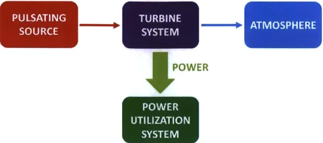
A conceptual view of the operation of turbine system within the context of vehicular turbocharger engine is shown in Figure 2-4. The pulsating source is the internal combustion engine and the power utilization system is the compressor. The focus is on the performance of Turbine System. Other blocks (Pulsating Source, Atmosphere, and Power Utilization System) are treated as boundaries (inlet stagnation pressure, inlet stagnation temperature, outlet static pressure, and power sink respectively).
POWER
Figure 2-4: Conceptual view - The turbine system receives flow from a pulsating source (internal combustion engine) and exhaust the flow to atmosphere. The ex-tracted power from the turbine system is utilized in another system (compressor).
The mesh for the turbine system (Figure 2-5) is composed of 7.5 million finite volume elements, on which RANS calculation is performed with commercial software ANSYS CFX. Turbulence model to be used is k-w SST (Shear Stress Transport) turbulence model with 5% initial turbulence intensity.
The turbine system consists of three sub-components (Figure 2-6): volute (where the wastegate port is attached), turbine wheel, and diffuser. Flow passes through the sub-components in sequence. The flow is taken either from inlet 1 or inlet 2 of the volute and then accelerated to a state where it is circumferentially distributed into turbine wheel. After the power is extracted, the flow is discharged to the diffuser where the static pressure is recovered to match the given static pressure at outlet. Also, it is noted that the length of the inlet pipes to the volute has been selected to match the volume of a representative manifold and piping on the engine.
The location of the wastegate port is in the inset region denoted with purple rect-angle in Figure 2-6. The purpose of the wastegate is to provide a direct path from the volute to the diffuser for flow to bypass the turbine wheel so as to protect the turbine wheel mechanically under over loading condition. Although the opening/closure of wastegate will not be considered in the thesis (thus the wastegate will remain closed),
(a) Overview (b) Mesh
Figure 2-5: Turbine System Overview - The geometric configuration in Figure (a) is meshed as shown in Figure (b).
the existence of the extrude port impact the flow beneath it via local flow sudden expansion. It leads to local entropy generation and this will be modeled with an appropriate wastegate port loss model to be described and presented in Chapter 4.
Setup of Unsteady CFD
Two different turbine system unsteady operations will be considered. One is "Peak Torque" (Turbine Operating Point) and the other is "Turbo Initial Transient". Peak Torque is the unsteady case where the speed of turbine wheel for turbocharger is sufficiently accelerated to attain the operating speed. In contrast, Turbo Initial Tran-sient is the unsteady case where the turbine wheel is still being accelerated toward the operating point.
The delay (typically around the order of 10 pulsation periods) between Turbo Initial Transient and Engine Rated Power is called turbo lag. And, it is desirable to minimize the delay. As such, a good performance and the corresponding larger torque and acceleration are the key design requirements on Turbo Initial Transient operation. In Chapter 5, we will discuss the possibility of improvement via installing variable inlet guide vanes on the Turbo Initial Transient operation.
For time-accurate unsteady computation, the time-resolved stagnation pressure and stagnation temperature variation at volute inlet is enforced as inlet boundary condition. Also, atmospheric static pressure is imposed at diffuser exit as outlet
TURBINE
Outlet
Wastegate port 2
Wastegate port 1
Figure 2-6: Turbine System Configuration -There are three components in the turbine system: volute, turbine and diffuser. The flow passes through the components in sequence. The flow is taken from inlet 1 or 2 of the volute and circumferentially distributed into the turbine wheel. After power is extracted from the flow in the turbine wheel, static pressure is recovered through the diffuser to match the ambient pressure at the outlet.
boundary condition. However, the time-varying turbine wheel rotation speed will not be considered since the variation is less than or order of 1% around the time averaged value. Lastly the time step is chosen as 1/12 of blade passing time while the interface model between the volute and the turbine wheel, and the turbine wheel and the diffuser is of the frozen rotor type approximation.
Setup of Steady CFD
For each unsteady operations (Peak Torque and Turbo Initial Transient), a finite set of steady CFD are implemented based on the boundary condition delineated in Figure 2-3.
'The ratio of the flow residence time through the turbine wheel to the turbine wheel rotation period is smaller than unity (around 0.3). This suggests the use of frozen rotor type approximation. Detailed argument about the utility of frozen rotor interface is discussed in Appendix A.
inlet 2 Inlet 1
... ....
2.3.2
Metric for Unsteady System Performance
Once the numerical results are available from steady CFD and unsteady CFD, a proper metric of unsteady system performance is needed to normalize the performance of each sub-component or the system as a whole. Preferably, this step should be conducted based on a physical basis in order to avoid non-physical results encountered by previous researchers as described in subsection 1.3.1.
2.4
Summary
This chapter presents the technical approach that is to be applied to the problem of interest: assessing the aerothermodynainics and operation of turbine wheel system under unsteady pulsating flow. An in-depth analysis for the unsteady turbine system is performed based on the framework presented in section 2.1. The flow characteristics and performance of each sub-component is analyzed and modeled. The analysis step is followed by integrating the sub-components for estimating the system performance. The minimum level of modeling, flow management strategy, and maximum power extraction condition will be addressed accordingly. Two unsteady operations will be considered (Peak Torque and Turbo Initial Transient) and unsteady/steady CFD will be implemented for each operation with representative boundary conditions. While the boundary condition for unsteady CFD is straightforward, the boundary condition for steady CFD has to be extracted from a given inlet pulsation.
Chapter 3
Metric for Unsteady System
Performance
There has been considerable confusion and controversy on defining and determining the performance of a turbine system operating in a pulsating flow environment. In this chapter, physical laws/principles are invoked to arrive at a physically consistent framework for quantifying the turbine system performance under pulsating flow.
3.1
Review of Steady Ideal Power
Steady isentropic efficiency is first reviewed on a concise basis before extending its utility to the unsteady flow situation. Most basic aerothermodynamics text would provide the derivation of isentropic efficiency (for example,
[3]).
Three physical prin-ciples for adiabatic system are used for the derivation:Mass conservation:
min - rout = 0 (3.1)
First Law of Thermodynamics:
hinhtin-
![Figure 1-1: 2010 BMW 4.4 L Gasoline Wastegate Twinscroll Turbocharger [1] - Note that the twinscroll turbine (left) is axially connected with the compressor (right)](https://thumb-eu.123doks.com/thumbv2/123doknet/13896758.447823/25.918.246.651.115.422/figure-gasoline-wastegate-twinscroll-turbocharger-twinscroll-connected-compressor.webp)