Design and Control of Miniature Air-and-Ground
Vehicles
by
Minoru Brandon Araki
B.S., Yale University (2014)
MASSACHUSETTS INSTITUTE OF TECHNOLOGYJUN 212017
LIBRARIES
ARCHIVES
Submitted to the Department of Mechanical Engineering
in partial fulfillment of the requirements for the degree of
Master of Science in Mechanical Engineering
at the
MASSACHUSETTS INSTITUTE OF TECHNOLOGY
June 2017
Massachusetts Institute of Technology 2017. All rights reserved.
./ ,~-~' /K
'-Author...
Certified by ...
Department of Mechanical Engineering
May 12, 2017
. . . .
Daniela Rus
Professor and Director of CSAIL
Thesis Supervisor
C ertified by ...
...
...
...
Sangbae Kim
Assistant Professor
Thesis Supervisor
ohan Abeyaratne
Accepted by.
Chairman, Department Committee on Graduate Theses
...
Design and Control of Miniature Air-and-Ground
Vehicles
by
Minoru Brandon Araki
B.S., Yale University (2014)
MASSACHUSETTS INSTITUTE OF TECHNOLOGYJUN 212017
LIBRARIES
ARCHIVES
Submitted to the Department of Mechanical Engineering
in partial fulfillment of the requirements for the degree of
Master of Science in Mechanical Engineering
at the
MASSACHUSETTS INSTITUTE OF TECHNOLOGY
June 2017
Massachusetts Institute of Technology 2017. All rights reserved.
Signature redacted
Department of Mechanical Engineering
Certified by.
Signature redacted
May 12, 2017
Certified by...
Accepted by.
Daniela Rus
Professor and Director of CSAIL
Z Tipis S" Prvicr
Signature
redacted-Assis
The
p
...Sangbae Kim
tant Professor
sis Supervisor
Signature redacted
...
...
"Rohan Abeyaratne
Chairman, Department Committee on Graduate Theses
Design and Control of Miniature Air-and-Ground Vehicles
by
Minoru Brandon Araki
Submitted to the Department of Mechanical Engineering on May 12, 2017, in partial fulfillment of the
requirements for the degree of
Master of Science in Mechanical Engineering
Abstract
The ability to both fly and drive is a superpower that few robots have. This thesis describes the design and control of two miniature air-and-ground vehicles, the "Flying Monkey" and the "Flying Car." The Flying Monkey was developed to demonstrate the viability and utility of miniature air-and-ground vehicles. The final design weighs
30g yet is capable of crawling, grasping, and flying. It features a novel crawling and
grasping mechanism that consists of 66 linkages yet weighs only 5.1 grams. Although the crawler is capable of only forward and backward motion, we designed a controller that uses the yaw torque of the propellers to give the Flying Monkey two degrees of freedom on the ground. In experiments we demonstrated that the Flying Monkey is able to grasp small objects, fly over obstacles, and crawl through narrow pipes. The Flying Car was designed as a swarm vehicle to test multi-robot path planning. We therefore made the Flying Car as simple and robust as possible, built a small swarm of them, and tested them in a miniature town. We present two of the first algorithms for multi-robot path planning for air-and-ground vehicles, one based on priority planning and the other based on multi-commodity network flow. Thus, by designing and testing robots, controllers, and algorithms for miniature air-and-ground vehicles, this thesis hopes to serve as a starting point for future research in this promising area of study. Thesis Supervisor: Daniela Rus
Title: Professor and Director of CSAIL Thesis Supervisor: Sangbae Kim Title: Assistant Professor
Acknowledgments
This thesis was made possible by many people besides myself. I would like to thank my research advisor, Daniela Rus, for taking me into her lab and giving me the opportunity to learn and do so many amazing things. I would also like to thank my many collaborators, particularly Jesung Koh, who helped with the mechanical design of the Flying Monkey; Daniel Aukes, who taught me how to use popupCAD and was a constant source of advice; Mike Tolley, who initially came up with the idea for the Flying Monkey; and Robert Wood, for allowing me to work in his lab and giving me a start in the world of research. I also need to thank Yash Mulgaonkar, who designed the Dragonfly quadrotor and who carried out the tests of the Flying Monkey; Luis Guerrero-Bonilla, who designed the controller for the Flying Monkey; Anurag Makineni, who helped write the code and run the system to control the Flying Monkey; and Vijay Kumar for supporting their work. Next I would like to thank my amazing UROP students Jack Strang, who wrote much of the code for the SIPP algorithm and the Flying Car simulator; Sarah Pohorecky, who was responsible for much of the Flying Car control, and Celine Qiu, who helped with the pure pursuit path following controller. I would like to thank Tobi Naegeli for his constant supply of quadcopter wisdom. I am also grateful to Robert Katzschmann and Cenk Baykal for their advice and help on the Flying Car project. Next, I would like to thank all of my labmates, past and present, for their help and friendship throughout my Master's studies. And last but far from least, I am grateful and thankful to my family, as well as to Kristi, for their constant love and support throughout my studies.
Contents
1 Introduction
1.1 Modes of Locomotion . . . . 1.2 Miniature Robots . . . .
1.3 Path Planning for Air-and-Ground Vehicles
1.4 Contributions . . . .
1.5 Organization of Thesis . . . .
2 Related Work
2.1 Miniature Air-and-Ground Vehicles . . . . 2.2 Foldable Robots . . . .
2.3 Path Planning . . . .
3 Design
3.1 Design of the Flying Monkey . . . .
3.1.1 Overview of Smart Composite Microstructures . . . .
3.1.2 Kinematic Design . . . .
3.1.3 Laminate Pattern Design . . . . 3.1.4 Fabrication . . . .
3.1.5 Dragonfly Quadrotor . . . .
3.1.6 Mass Distribution . . . .
3.2 Design of the Flying Car . . . .
3.2.1 Crazyflie Quadrotor . . . . 3.2.2 W heel Base . . . . 15 16 18 19 19 20 21 21 23 25 27 27 27 28 29 32 34 36 36 37 37
. . . .
. . . .
. . . .
. . . .
. . . .
3.2.3
Optical Tracking . . . .
3.2.4
Mass Distribution. . . . .
4 Control4.1 Control of the Flying Monkey . . . .
4.1.1 Ground Locomotion . . . .
4.1.2 Aerial Locomotion . . . .
4.2 Control of the Flying Car . . . .
4.2.1 Ground Locomotion . . . .
4.2.2 Aerial Locomotion . . . .
5 Planning
5.1 Problem Statement . . . .
5.2 Problem Formulation . . . .
5.3 Graph Data Structure . . . .
5.4 Objective Function . . . .
5.5 Battery Life . . . .
5.6 Priority Planning with SIPP . . . .
5.7 Multi-commodity flow with ILP . . . .
6 Experiments & Results
6.1 Flying Monkey Experiments & Results
6.1.1
Software Architecture . . . .
6.1.2
Energetics at hover . . . .
6.1.3
Energetics during crawling . . . . .
6.1.4
Cost of transportation . . . .
6.1.5
Gripper . . . .
6.1.6
Regulation and Time Parameterized
6.2 Flying Car Experiments & Results . . . .
6.2.1
System Architecture . . . .
6.2.2
Energetics . . . .
. . . .
. . . .
. . . .
. . . .
. . . .
. . . .
Trajectory Tracking . . . . . . . . . . . .38
39
41
41
41
43
44
44
46
47
47
48
48
49
50
51
54
57
57
57
58
59
60
61
61
63
63
64
6.2.3 Simulation . . . . 66
6.2.4 Physical Experiment . . . . 67
7 Future Work & Conclusion
71
7.1 Future Work . . . . 71
7.2 Conclusion . . . . 72
List of Figures
1-1 Modes of robot locomotion . . . . 16
1-2 The two air-and-ground vehicles explored in this thesis . . . . 20
2-1 Other air-and-ground vehicles . . . . 22
2-2 Several foldable robots . . . . 23
3-1 A folded model of the Flying Monkey's base. . . . . 28
3-2 Diagram of SCM flexures . . . . 28
3-3 A kinematic diagram of the Flying Monkey's crawling mechanism . . 29
3-4 The laminate design of the Flying Monkey . . . . 30
3-5 The relationship between the abstract kinematic diagram and the the laminate pattern design . . . . 31
3-6 The series four bar and gripping mechanisms . . . . 32
3-7 Images of the gripper open and closed . . . . 32
3-8 The materials used to make the laminate . . . . 33
3-9 The design process. . . . . 34
3-10 The pop-up fabrication process . . . . 34
3-11 Components of the Dragonfly quadrotor . . . . 35
3-12 The Crazyflie 2.0 and the Crazyradio PA . . . . 37
3-13 Pinout for Crazyflie 2.0 decks . . . . 38
3-14 The wheel deck PCB and the deck configuration of the Crazyflie 2.0 . 38 3-15 Two views of the driving mechanism of the Flying Car . . . . 39
4-2 Position and attitude control of the Dragonfly quadrotor . . . .
5-1 Graph structure of the Flying Car environment . . . . 6-1 Software architecture for controlling the Flying Monkey . . . .
6-2 Pictures of the Flying Monkey in action . . . . 6-3 Power draw of the Dragonfly quadrotor and the Flying Monkey . . .
6-4 Power draw of the Flying Monkey while crawling . . . .
6-5 Experimental results of the Flying Monkey's maximum gripping load
6-6 Controller performance . . . .
6-7 Flying Car system architecture . . . . 6-8 Driving and flight paths of three flying cars . . . . 6-9 Power draw comparison of the Crazyflie, Flying Car, and wheel base . 6-10 Simulation experiments .
6-11 6-12 6-13
Planning times vs. number of vehicles and average Paths for 20 vehicles with flying and driving. . . .
Experimental and simulated flying cars . . . .
A-1 Layer 1 of the Flying Monkey A-2 Layer 2 of the Flying Monkey A-3 Layer 3 of the Flying Monkey
A-4 Layer 4 of the Flying Monkey
A-5 Layer 5 of the Flying Monkey A-6 Final Cut of Top Laminate of the A-7 Layer 7 of the Flying Monkey A-8 Layer 8 of the Flying Monkey .
A-9 Layer 9 of the Flying Monkey .
A-10 Layer 10 of the Flying Monkey. A-11 Layer 11 of the Flying Monkey.
cost of paths
Flying Monkey
A-12 Final Cut of Bottom Laminate of the Flying Monkey
43 49 57 59 60 60 62 63 64 65 66 66 67 68 69 76 77 78 79 80 81 82 83 84 85 86 87
List of Tables
1.1 Comparison of aerial, terrestrial, and aerial + terrestrial locomotion 17
1.2 Comparison of large and small robots . . . . 19
3.1 Masses of the elements of the Flying Monkey . . . . 36
3.2 Masses of the elements of the Flying Car . . . . 39
6.1 Comparison of the energetics of the Dragonfly, Flying Monkey, and
craw ler . . . . 61
6.2 Comparison of the energetics of the Crazyflie, Flying Car, and wheel
Chapter 1
Introduction
Nearly all animals that can fly can also walk. Birds, bats, and insects all come equipped with legs and feet despite the energetic burden of carrying them. Even though aerial locomotion is faster, more agile, and, in the case of animals, more efficient than walking, the ability to maneuver on solid surfaces safely and efficiently is extremely valuable. It allows animals to perform tasks that require dexterity and precision, such as feeding their young, gathering food, and interacting with others. So why is it that so few of today's flying robots, particularly small ones such as quadrotors, have any form of ground locomotion? There are countless scenarios in which the ability to maneuver on the ground would greatly benefit a flying robot. For example, a quadrotor with wheels could drive through a narrow tunnel, orient itself on a platform to take a picture, or station itself to collect data. Meanwhile, it is also easy to imagine scenarios in which a ground robot would benefit from the ability to
fly. For example, a search-and-rescue robot could fly over a pile of debris instead of
needing to climb over it, or a flying car could whisk passengers over buildings and traffic to reach its destination quickly.
In this thesis, I explore the idea of multimodal locomotion by describing the design and control of two miniature air-and-ground vehicles. But first, why air-and-ground vehicles? And why miniature?
Modes of Robot Locomotion
a
d
Stationary
Terrestrial
Aquatic
Aerial
Figure 1-1: Robots have at least four general modes of locomotion. a) Stationary
robots such as this Fanuc Arcmate 100IC/7L arm do not move. b) Terrestrial robots
like this iRobot Roomba 560 are confined to the ground. c) Aquatic robots including
this DiveLog Automated Survey Boat by Shark Marine Technologies stick to the
water. d) Aerial robots, for example this DJI Phantom 2 Vision+ quadrotor, navigate
through the air.
1.1
Modes of Locomotion
Robots can be divided into four general classes based on mobility, shown in Fig. 1-1.
The most widely used are stationary robots
-
the robotic arms on factory floors, which
are secured tightly to the ground. Second are terrestrial vehicles, such as autonomous
cars and Roombas. Third are aquatic robots, such as autonomous submarines and
boats. And fourth are aerial vehicles, such as quadrotors and other UAVs. Since
stationary robots are not mobile and aquatic robots are usually highly specialized, I
narrowed my focus to considering only ground and aerial locomotion for this thesis.
My goal was to combine aerial and terrestrial locomotion in a way that could enhance
the mobility of a robot.
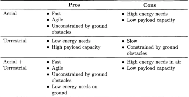
In summary (see Table 1.1), ground robots are slow and highly constrained
com-pared to aerial robots, but they also have a higher payload capacity and lower energy
needs for a given payload. By contrast, aerial vehicles, particularly quadrotors, are
fast and can easily navigate around most obstacles, but they have high energy needs
and a low payload capacity.
In nature, flying is actually a more efficient form of locomotion than walking
or crawling [1]. Yet, despite the energetic cost of carrying a set of legs to walk on,
almost all animals that can fly also have some form of terrestrial locomotion. Amongst
Pros Cons
Aerial * Fast * High energy needs
* Agile * Low payload capacity * Unconstrained by ground
obstacles
Terrestrial e Low energy needs * Slow
* High payload capacity * Constrained by ground obstacles
Aerial + * Fast * High energy needs in air
Terrestrial o Agile * Low payload capacity
* Unconstrained by ground obstacles
* Low energy needs on ground
Table 1.1: Comparison of aerial, terrestrial, and aerial + terrestrial locomotion
birds, for example, only highly specialized birds such as hummingbirds and loons have difficulty walking. So why is it that almost all robots have been designed for either ground or aerial locomotion, but not both? One of the main reasons, which will be elaborated upon in Chapter 2, is that the weight of the ground mechanism would be too great for the aerial vehicle to carry or would reduce the robot's flight time to be impractically short. Another is that adding a second mode of locomotion increases the cost of the vehicle. However, I believe that these reasons are a poor excuse to not study robots with combined aerial and ground locomotion. First of all, battery energy density will inevitably improve in the future, easing the payload and energy constraints on aerial vehicles. Second of all, one can work around the payload and energy constraints by making the driving mechanism lighter or by automating the battery recharging process so that a swarm of flying-and-driving vehicles can stay in the air at all times. And third of all, combining aerial and ground locomotion in a single vehicle results in significant improvements in mobility.
By combining aerial and ground locomotion, as shown in Table. 1.1, it is possible
to have all of the benefits of aerial locomotion plus the option to switch to low en-ergy travel on the ground. This allows an air-and-ground vehicle to fly over ground
obstacles, drive through narrow passages, and prioritize between speed and energy efficiency while traveling. The only costs incurred by having air-and-ground capabil-ities is that the weight of the terrestrial locomotion mechanism slightly increases the energy needs and reduces the payload capacity of the robot. However, these limita-tions can be mitigated by making the terrestrial locomotion mechanism as light as possible, as discussed in Chapter 3.
I expect that in the future, robots with both aerial and ground locomotion will be used in a variety of tasks. For example, a surveillance robot could fly into an air shaft, crawl through the air ducts, and park itself near a vent to gather information. Once its mission is complete, it could then crawl back out and transmit its data. Or, a search-and-rescue robot could enter an earthquake-damaged building and fly over piles of rubble and crawl through narrow openings in order to map out the building for rescuers. As materials science and manufacturing techniques enable batteries with higher energy density and actuators with higher power density, I expect that it will one day be taken for granted that aerial robots have some form of ground locomotion.
1.2
Miniature Robots
In this thesis, I specifically study miniature air-and-ground robots. Why miniature? Some of the reasons are listed in Table 1.2. Both the pros and cons of small robots make them an interesting subject of study. First of all, small robots are easier to work with since they are safer, cheaper, and stronger in relation to their size. Second of all,
the constraints on small robots - a shorter battery life and lower payload capacity,
along with their small size - elevate the challenge of constructing a lightweight ground
mechanism into a research problem. For example, attaching landing and taxiing gear to the General Atomics MQ-9 Reaper drone, which has a wingspan of 84 feet, is not a research challenge. I therefore focused on designing ground mechanisms for small quadrotors, which have extreme payload and energy constraints, since that is where the open research challenges are.
Pros Cons
Small 9 Stronger * Shorter battery life
e Safer * Low payload capacity
* Cheaper
Big * High payload capacity * Weaker
* Longer battery life * Safety hazard
* More expensive
Table 1.2: Comparison of large and small robots
1.3
Path Planning for Air-and-Ground Vehicles
Given a robot that can both fly and drive, how does one choose paths for it? Aerial locomotion is fast but energy-expensive, whereas ground locomotion is slow but effi-cient. The value placed on speed versus efficiency forms a natural basis for choosing when and where to fly or drive. As will be discussed in Chapter 2, air-and-ground robots have been so little studied that there is almost no literature on path planning for robots with multimodal locomotion. Therefore, another major thrust of this thesis is proposing and testing algorithms that solve the path planning problem for multiple air-and-ground vehicles.
1.4
Contributions
I make three main contributions to the existing literature in this thesis:
1. A novel crawling and grasping mechanism fabricated using smart composite
microstructures manufacturing.
2. A hardware platform for a miniature wheel-based robot that can fly and a system architecture for a swarm of such robots.
3. Two modified algorithms for multi-robot path planning with multimodal
(a) The Flying Monkey [see Section 3.1] (b) The Flying Car [see Section 3.2]
Figure 1-2: The two air-and-ground vehicles explored in this thesis
1.5
Organization of Thesis
In this thesis, I describe the design and control of two miniature air-and-ground vehicles, the Flying Monkey (Fig. 1-2a) and the Flying Car (Fig. 1-2b). In Chapter 2, I discuss the background of air-and-ground vehicles, foldable robots, and multi-robot path planning. Chapter 3 describes the design of the Flying Monkey and the Flying Car. Chapter 4 explains the control of each vehicle. Chapter 5 covers multi-robot path planning for the Flying Car. Chapter 6 describes the experiments done with the Flying Monkey and the Flying Car that validate the effort put into their design, control, and path planning.
Chapter 2
Related Work
2.1
Miniature Air-and-Ground Vehicles
The field of miniature air-and-ground vehicles is small but slowly growing. Re-searchers have come up with diverse strategies for coping with the low payload of flying vehicles, but of the six designs surveyed here, four of them save weight by inte-grating the aerial and terrestrial locomotion mechanisms. For example, the DALER robot, shown in Fig. 2-1c, moves on the ground by rotating its wings. This clever use of the wings eliminates the need for a separate ground mechanism. Meanwhile, the Quadroller (Fig. 2-la), HyTAQ (Fig. 2-le), and Flymobile (Fig. 2-1f) are quadrotors on passive wheels that employ various clever mechanisms that allow their propellers to propel them when they are on the ground.
The other major category of air-and-ground vehicle treats the aerial and terrestrial-locomotion mechanisms as independent subsystems. A unit of the Distributed Flight Array (Fig. 2-1b) uses a singe large propeller to fly (they must be attached to other units to fly stably) and has three independent omniwheels for ground locomotion. MALV (Fig. 2-1d) uses flexible wings and a propeller to fly and crawls on the ground using 'whegs,' which are leg-like wheels. The Distributed Flight Array can overcome the payload limitation of aerial vehicles because a single unit has a proportionally huge propeller compared to the size of the omniwheels - therefore, when at least three units are joined, the vehicle is not miniature but quite large, meaning that the
Elj
El
dl
Figure 2-1: Researchers have come up with many ingenious designs for miniature
air-and-ground vehicles. a) The Quadroller tilts to move forward on land [2]. b) Each
unit of the Distributed Flight Array consists of a propeller and three omniwheels [3].
c) DALER can rotate its wings to move on the ground [4]. d) MALV has flexible
wings and a propeller for aerial locomotion and 'whegs' for terrestrial locomotion [5].
e) HyTAQ moves on the ground by spinning in a cage [6]. f) The Flymobile tilts its
rotors by
900
to propel itself on the ground [7]. All photos used with the permission
of the authors.
omniwheels are proportionally very small and light. MALV gets around the weight
limit by using clever materials and manufacturing techniques
-
the flexible wings and
whegs are very lightweight.
The Flying Monkey's crawling mechanism has a single motor for forward and
backward motion. It therefore must rely on its propellers for steering while on the
ground. Moreover, smart composite microstructures techniques were used to supply
the Flying Monkey with an extremely lightweight and robust crawling and grasping
mechanism. The Flying Monkey is therefore a hybrid of the strategies discussed above.
By contrast, the driving mechanism of the Flying Car is innovative in its simplicity
-
it is a three-wheeled differentially steered mechanism that is independent from the
F T]
10cm
Figure 2-2: (a) The DASH robot served as the inspiration for the Flying Monkey [8].
(b) The MIT FireAnt robot is a foldable 12-dof hexapod [9]. (c) Harvard's HAMR
weighs only 2.1g [10].
flying mechanism. The simplicity of the Flying Car's design allowed us to make and
test many of them in a multi-robot system, as will be discussion in Chapter 5. The
design of the Flying Monkey and the Flying Car will be discussed in Chapter 3.
2.2
Foldable Robots
In recent years, the idea of creating 3D mechanisms by first manufacturing a 2D
design and then folding it has been gaining traction. The field of foldable robots was
inspired by the art of origami, in which intricate 3D shapes can be folded from a
sheet of paper. Since 2D manufacturing typically involves planar sheets of material
and a laser cutter, production is fast and cheap. Researchers have devised many
manufacturing techniques to develop a vast array of designs. One method of making
foldable robots is to cut and score a single sheet of plastic, which can then be folded
into a final shape. [9] (see Fig. 2-2b) describes the design of a 6-legged, 12-DOF
ant-like robot. [11] made a crawling robot and a gripper; the two 2D designs were then
combined by connecting them with a bridge, enabling the manufacture of a crawling
robot with a gripper. [12] describes a fold pattern that enables the creation of a wide
range of cylindrical robots that can move using a worm-like peristaltic motion. [13]
presents a Python package that automatically generates cut patterns for quadrotor
frames that can be cut and folded from a sheet of plastic. Although the technique of
folding a robot or structure from a single sheet of plastic has been successfully applied
to a wide variety of robots, the use of a single type of material (typically a thin sheet of plastic) limits the performance of these robots.
The concept of smart composite materials [14], which will be further discussed in Section 3.1.1, addresses the shortcomings of using a single sheet of plastic by introducing the concept of laminates composed of both rigid and flexible layers. Cuts in the rigid and flexible layers allow the creation of flexures and rigid links. Since the rigid layer (typically fiber glass or carbon fiber) can be selected to be far stiffer than the flexible layer (typically thin plastic), far higher performance can be gained from
SCM robots. Examples of SCM robots include the Robobee, a 60mg robot that can fly [15], and the Harvard Ambulatory Microrobot (HAMR), a 2.1g robot quadrupedal
robot that can travel up to 4 body lengths/sec [10] (see Fig. 2-2c). Other examples of SCM robots include a water strider robot that takes of advantage of the surface tension of its legs on water to jump as efficiently as an actual water strider [16] and a myriapod robot that weighs 2.2 grams yet has 20 legs and can run at over 1 body length/sec [17]. The DASH robot (see Fig. 2-2a), which served as the primary inspiration for the Flying Monkey (as will be discussed in Section 3.1.2) was also constructed using laminates. Due to the high performance, intricate design, and light weight made possible by SCM techniques, the Flying Monkey was also designed and manufactured as an SCM robot.
Several design programs have been made to either automatically generate fold-able robots or make the design of foldfold-able robots easier. [18] presents a system for automatically generating foldable designs, wiring instructions, and code based off of high-level user specifications. Its system has a library of parametrically defined robot parts such as legs, wheels, and bodies, which can be modified and stitched together to satisfy the user's requirements. The Interactive Robogami system presented in
[19] also has a library of expertly designed parts that can be composed into a single
robot. However, it provides an interactive 3D environment in which users can design their own robot themselves by dragging and dropping and modifying components.
The software used in this thesis is called popupCAD [20]. Unlike the previously
allows low-level operations on planar geometries (such as union and difference func-tions) that allow the creation of complicated laminate structures. popupCAD greatly speeds up the design process by providing a placement operation that enables sub-designs (such as a hinge) to be composed with another design (such as a hinged robot). popupCAD also provides operations such as support generation that enables the generation of manufacturable vector files for use with a mill or laser cutter. Prior to the development of popupCAD, all of these operations involved in SCM laminate design had to be done by hand in a CAD environment such as Solidworks. popupCAD was invaluable to the design of the Flying Monkey (as described in Section 3.1.4).
2.3
Path Planning
The problem of path planning for air-and-ground vehicles has received little attention
- I have been able to find only one paper that addresses the subject, 3D Path Planning
for Flying/Crawling Robots, by Rao and Arkin, published in 1989 [21]. Rao and Arkin proposed using A* to find a lowest-cost path on a discrete 3D grid on which flying and crawling costs have been computed. This thesis picks up where Rao and Arkin
left off by extending the path planning problem to the multi-robot domain.
However, the multi-robot path planning problem (MPP) for robots with a single mode of locomotion has been the subject of extensive research. MPP is a challeng-ing problem because the configuration space grows exponentially with the number
of robots [22]. It can be made tractable through decentralized solutions such as
[23, 24, 25] that delegate to each robot the responsibility for avoiding other robots.
Centralized algorithms exist that can find feasible collision-free paths for multiple robots in O(n3) time or faster [26]. Priority planning is a suboptimal but fast
central-ized solution to MPP in which priorities are assigned to robots and paths are then found for each robot in order of its priority [27, 28]. A number of tricks exist for mak-ing priority plannmak-ing better. For example, [29] suggests limitmak-ing the plannmak-ing horizon, rotating priorities amongst robots, and using a true distance heuristic to get better paths from priority planning. [28] proposes the idea of well-formed infrastructures in
order to generate graphs and scenarios with guaranteed solutions. Meanwhile,
ap-proaches such as [30, 31] provide optimal solutions but become intractable when the
graph size or number of robots goes past a certain limit. However, these problems
can be made tractable by allowing for suboptimal solutions by for example splitting
the problem into multiple smaller problems in the time domain. I contributed to this
literature by extending MPP to include robots with multiple modes of locomotion.
Chapter 5 describes two algorithms, one a fast priority planner and the other an
op-timal ILP, to show that the MPP can be extended to include the modified objective
function of flying cars.
Chapter 3
Design
3.1
Design of the Flying Monkey
The Flying Monkey is a 30g robot with the ability to fly, crawl, and grasp. My principle contribution to the design of the Flying Monkey was its gripper and crawling base, shown in Fig. 3-1. The two mechanisms and their actuators had to weigh less than the quadrotor's 10g payload capacity. I created the Flying Monkey's base using the techniques of smart composite microstructure fabrication, since they are uniquely suited for designing and manufacturing lightweight yet complex mechanisms.
3.1.1
Overview of Smart Composite Microstructures
Smart composite microstructures (SCM) technology uses laminates consisting of stiff and flexible layers to create complex mechanisms [14]. Diagrams of a typical SCM laminate are shown in Fig. 3-2. Flexures can be easily made by cutting gaps in the rigid layer. The areas where the rigid layers are present define links, while gaps in the rigid layers that expose the flexible layer define hinges. These laminates enable the design of 2D patterns which, once manufactured, can be folded into functional
3D mechanisms.
Recent advances in techniques for analyzing laminate geometries, determining manufacturability, and automating the creation of laminate device manufacturing files
Gripper
Series four-bar mechanism
Six-bar leg mechanism
Figure 3-1: A folded model of the Flying Monkey's base.
polymer composite
link flexure link (rigid) (compliant) (rigid)
(a) (b)
Figure 3-2: (a) Links and flexures are created by cutting gaps in the rigid layer. (b)
The gap in the rigid layer allows the flexible layer to bend. Diagrams from [14].
have made designing and manufacturing SCM devices into a fast and simple process
[32]. Furthermore, functional components such as hinges and four-bar linkages can
be saved and reused in an object-oriented fashion using a purpose-built software tool
called popupCAD [20], a design suite that stores and operates upon layered sets of
planar geometries. popupCAD also provides operations for converting the laminate
design into the vector files needed for manufacturing.
3.1.2
Kinematic Design
The kinematic design of the crawling mechanism was based off of UC Berkeley's
x
Figure 3-3: A kinematic diagram of the Flying Monkey's crawling mechanism. The
diagram on the left shows how the actuator input results in output motion of the
feet. The diagram on the right shows the overall structure of the crawler.
that actuates six legs. I modified this design to be the one shown in Fig. 3-3. In
this design, every 'foot' is attached to a 4-bar linkage, or 'hip', that allows fore-aft
motion. Each foot consists of an inner foot and an outer foot. Each hip is connected to
a central 1-DOF 6-bar mechanism that is constrained to be able to move in a circular
pattern in the x-z plane. A motor with a crank is attached to the 6-bar mechanism
by a shaft. As the crank turns, it causes the 6-bar mechanism to trace out a circle.
As the 6-bar mechanism moves up and down, it causes the hips to pivot inwards and
outwards, respectively, causing the outer feet to move down and up and the inner
feet to move up and down. As the 6-bar mechanism moves forward and backward,
it causes the hips to rotate as well, causing the outer feet to move backward and
forward and the inner feet to move forward and backward. In summary, the rotary
motion of the crank and the 6-bar mechanism causes the outer and inner feet to trace
out alternating circular strokes. When the four outer feet are touching the ground,
the four inner feet are not; and when the four inner feet are touching the ground, the
outer feet are in the air. This allows the leg mechanism to move forward in a stable
configuration.
3.1.3
Laminate Pattern Design
The final laminate design of the Flying Monkey is shown in Fig. 3-4. It consists of 66
rigid elements. Each bounded area represents a linkage. Dotted lines represent hinges
Bottom Layer
Top Layer
Ground Frame Feet . .Leg Mechanism .. Folding Tabs Constraint GripperFigure 3-4: The laminate design of the Flying Monkey. The links are color-coded to
correspond to functional regions.
and solid lines represent cuts. The design consists of two sublaminates, a top layer
and a bottom layer, which themselves are glued together to form a single composite
laminate. Folding tabs, shown in orange, constitute an important part of the design
beyond the kinematic plan, because by being folded and glued into place, they hold
the folded design together and help to rigidize it.
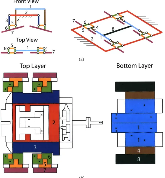
The correspondence of each link in the abstract kinematic design to a link in the
laminate pattern design is shown in Fig. 3-5. For example, the Flying Monkey has
four 'hips', each of which is a 4-bar linkage. In Fig. 3-5a, the links of the hips are
colored as orange and green. The corresponding links in Fig. 3-5b are also colored
orange and green. Some of the links have also been numbered to help clarify the
relationship between the individual links. For example, one of the hips in Fig. 3-5a
has been labeled with the numbers 5 and 6. The corresponding links in Fig. 3-5 have
also been labeled 5 and 6.
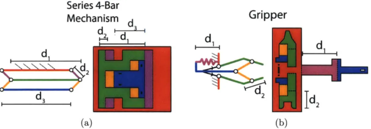
Two other major components of the laminate design are shown in Fig. 3-6. On the
left of each subfigure is the abstract design and on the right is the laminate design.
As in Fig. 3-5, the linkages are color-coded to show the correspondence between the
abstract and laminate designs. In addition, linkage lengths are labeled. Fig. 3-6a
shows the series 4-bar mechanism. Since the crawling mechanism is one DOF, the
6-Front View
1qJ
2~
6 7
Top View
6 5
1
SIEX7
Top Layer
2; I I
7
6
5
4
8
21
(a)Bottom Layer
---.---.---.
.
.... 1...
(b)Figure 3-5: This figure shows the relationship between the abstract kinematic design
(a) and the laminate pattern design (b). Linkages are numbered and color-coded to
relate the kinematic linkages to the corresponding linkages of the laminate.
bar leg mechanism must be constrained to a single DOF. The series 4-bar mechanism
serves this purpose by constraining the leg mechanism to a circular motion in the x-z
plane.
4-Series 4-Bar
Mechanism d
Gripper
d
' -I
d
d
dd
3 2Id2
(a) (b)Figure 3-6: (a) The series four bar constraint mechanism. (b) The gripping
mecha-nism.
bar mechanisms with extensions that can be pulled together and pushed apart. It
is unique among laminate pop-up designs in that it uses a built-in passive spring,
colored in purple, to pull the gripper open. This is achieved by bending the blue and
purple linkages so that the blue linkage slots into the small rectangular hole in the red
linkage. This built-in spring pulls the gripper mechanism back so that the gripper's
default state is open. A thin shape-memory alloy coil (shown as two black lines with
arrows in the abstract kinematic diagram) pulls the gripper closed for short periods
of time. Fig. 3-7 shows a closeup of the gripper in its open (Fig. 3-7b) and closed
(Fig. 3-7a) positions. On the Flying Monkey, the onboard micro-controller controls
the SMA actuator through one of the digital outputs and a high power MOSFET.
(a) Gripper closed
(b) Gripper open
Figure 3-7: Images of the gripper open and closed
3.1.4
Fabrication
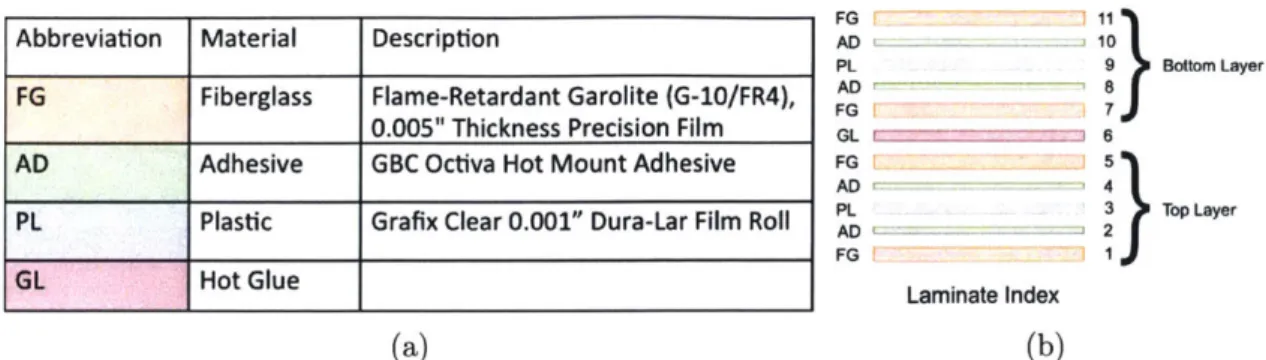
As discussed in the previous section, the laminate is composed of two five-layer
sub-laminates bound together by an additional adhesive layer. The order of the eleven
Abbreviation Material Description
FG Fiberglass Flame-Retardant Garolite (G-10/FR4), 0.005" Thickness Precision Film
AD Adhesive GBC Octiva Hot Mount Adhesive
PL Plastic Grafix Clear 0.001" Dura-Lar Film Roll
GL Hot Glue FG 1 11 A D 10 PL 9 Bottom Layer AD 8 FG FD 7J GL 6 FG L ~ 5 AD 4 PL 3 Top Layer AD 2 FG 1 Laminate Index (a) (b)
Figure 3-8: (a) The materials used to create the laminate design. (b) The ordering of the layers.
layers is shown in Fig. 3-8b, and the materials used are listed in Fig. 3-8a. The fiber-glass serves as a rigid element that keeps the linkages stiff. The plastic layer servers as the flexible element in every hinge. The adhesive layers, meanwhile, bind the rigid and flexible layers together.
The design process is outlined in Fig. 3-9. First, the 2D laminate pattern is sketched in Solidworks. Although the pattern could be made in any vector graphics program, one benefit of using Solidworks is that the design can be tested by making the linkages into an assembly, adding appropriate constraints between them, and fold-ing them into the final design. Next, the Solidworks sketch is exported to popupCAD.
I have created custom zero-radius hinge designs in popupCAD which are added to the
design. popupCAD then outputs vector files for the laser cutter for all of the layers of the laminate (see Figs. A-1 through A-12). A laser cutter and laminator are then used to cut and laminate the layers of material (as described in the next paragraph),
and the finished laminate is hand folded into the final shape.
Fabrication of pop-up laminate devices - in other words, the process of turning
flat sheets of multiple materials into a popup device - is described in [33]. The general process is illustrated in Fig. 3-10. I will describe my particular process here:
1. Preparation: A laser cutter is used to cut the layers of the laminate.
2. Layer Addition: The layers are aligned and stacked on top of each other.
3. Lamination: The layers are then passed through a laminator.
Solidworks
-
popupCAD
-
Laser cutter
+
-
Hand Fold
Laminator
s7,
V
Figure 3-9: The design process.
Selective ition Mreparaion
& Machining mna ion
Layer W on
e ease ut Pop-up & Lock
Figure 3-10: The pop-up fabrication process, as described in [33].
release them
5. Pop-up & Lock: The two finished laminates are glued together to form the final
composite laminate
3.1.5
Dragonfly Quadrotor
The Dragonfly quadrotor used as the flying chassis for the Flying Monkey was
de-signed by Yash Mulgaonkar of the University of Pennsylvania [35, 34]. It weighs 24g
and is constructed from a 0.047" thick double layer fiber-glass PCB. It is fast and
very agile, capable of reaching speeds of up to 6m/s and coming to a full stop within
a 4m x 4m flight space.
, .-
58.22mm
E
c6
LO)
"
ARM Cortex M4 Processor
e 5x Motor Drivers
* ZigBee 802.15.4 Transceiver
*LiPo Battery Charger
" MPU-6050 6-Axis IMU
*Inductive Charger Contacts
Power Management Circuit
*USB Comms/Charger
" High Resolution Barometer
*UART / 12C Interface
Figure 3-11: Components of the Dragonfly quadrotor, as described in [34].
and lightweight as possible. Almost all commercially available autopilots, such as
the PX4 Pixhawk [36], though feature-rich, are too bulky for a micro quadrotor,
weighing close to 36g, with a footprint averaging about 40cm
2. In contrast, the
Dragonfly's autopilot, shown in Fig. 3-11 spans only 3cm
2and weighs 4.8g. The
Dragonfly is equipped with an ARM Cortex M4 STM32F373 microprocessor, which
interfaces with Atmel's AT86RF212 900MHz 802.15.4 wireless transceiver chip. An
InvenSense MPU-6050 6-axis MEMS gyroscope & accelerometer and a Measurement
Specialties MS5611 high precision barometer allow for accurate attitude and altitude
measurement, while a 3.3v Buck/Boost switching regulator powers all the subsystems
while maintaining a consistent logic level throughout the circuit. Five 4A DC brushed
motor drivers power the motors and an integrated Lithium Polymer (LiPo) battery
charging circuit allows for in-system charging of the on-board battery. A micro USB
port and two multipurpose 12C and UART ports allow for interfacing with a wide
range of external sensors.
component of the Dragonfly, eliminating the need for an additional load bearing frame. 3D printed snap-on motor mounts are used to attach the motors to the autopilot. Finally, a single cell 3.7V, 240mAh Li-Po battery powers the Dragonfly, giving it a six minute flight time.
3.1.6
Mass Distribution
Table 3.1 shows the distribution of mass in the Flying Monkey. Its total mass is 30g. Given that the Dragonfly's maximum payload capacity is 10g, the crawler, which weighs only 5.1g, comes in well under the limit. Another 0.9g are used to up to attach the crawling base to the Dragonfly, meaning that the Flying Monkey could theoretically carry a payload of up to 4g.
Mass Table
Item Mass (g) Mass Percent
Crawler 5.1 g 17%
Battery 8.1 g 27%
Dragonfly 15.9 g 53%
Misc. 0.9 g 3%
Total 30.0 g 100%
Table 3.1: Masses of the elements of the Flying Monkey
3.2
Design of the Flying Car
The Flying Car was designed to be the successor to the Flying Monkey and was intended to be used in a swarm. Therefore the goal of the design of the Flying Car was to make as small, reliable, robust, and easy-to-manufacture an air-and-ground vehicle as possible. As described in the following sections, this was accomplished
by replacing the custom-made Dragonfly quadrotor with the commercially available
Crazyflie 2.0 and by replacing the intricate crawling mechanism of the Flying Monkey with an extremely simple and robust two-motor differentially steered mechanism.
I1
U U
(a) The Crazyflie 2.0 (b) The Crazyradio PA Dongle
Figure 3-12: The Crazyflie 2.0 and Crazyradio PA were two important components of the Flying Car made by bitcraze. io.
3.2.1
Crazyflie Quadrotor
The Crazyflie 2.0 is a commercially available, highly versatile 27g quadrotor (see Fig. 3-12a). It has a 240 mAh Li-Po battery that provides 5 minutes of flight. Given that it has a payload capacity of 15g (56% of its body weight) and is fully open-source, it makes an ideal platform for research involving micro aerial vehicles. Moreover, it can communicate with a computer via a 2.4 GHz radio dongle called the Crazyradio PA, shown in Fig. 3-12b.
3.2.2
Wheel Base
The Crazyflie 2.0 is designed to accommodate expansion boards called 'decks' that can be used to add new functions to the Crazyflie. Decks interface with the Crazyflie via certain pins as shown in Fig. 3-13. I designed a wheel deck for the Crazyflie that adds a motor driver and a pair of motors to the bottom of the Crazyflie, as in Fig. 3-14b. I designed the deck to be as lightweight and robust as possible. It consists of a
1/32" thick PCB, shown in Fig. 3-14a with a TI DRV8835 dual motor driver mounted
on top, and a 6mm carbon fiber tube glued with epoxy to the PCB that serves as the fixture for two 1.2g 136:1 micro planetary gear motors. The wheel mechanism can be seen in Fig. 3-15. The customized firmware that runs the wheel deck can be found at
T- 0 0 CH -W
_______________ )NRF51
% Power. VUSB is IN/OUT other are OUT
2c4Connection on MCUs 1NRF51 GPIOs Communication PWM, grouped by timer It STM32F4 GPIOs Analog input
Figure 3-13: Pinout for Crazyflie 2.0 decks [37].
r -1Crazyfl ie 2.0
Wheel Base
(a) Wheel deck PCB, units in mm (b) The deck configuration of the Crazyflie 2.0
Figure 3-14
https : //github. com/braraki/crazyflie-firmware.
3.2.3
Optical Tracking
A Vicon motion capture system was used to track the Flying Cars. Thin, lightweight
frames made from Delrin based off of the design in [38] were made to hold the optical markers. Since a total of seven flying cars were meant to be controlled at once, seven unique optical marker configurations were made so that the Vicon system could distinguish between them.
(a) A model of the underside of the Flying Car
(b) The underside of the Flying Car
Figure 3-15: Two views of the driving mechanism of the Flying Car
3.2.4
Mass Distribution
The mass distribution of the Flying Car is shown in Table 3.2. The driving mecha-nism, at 8.3g, weighs more than the Flying Monkey's 5g crawling base. However, it is still well under the Crazyflie's 15g payload capacity.
Mass Table
Item Mass (g) Mass Percent
Wheel Base 8.3 g 20.2%
Motion Capture Markers 4.2 g 10.2%
Crazyflie 28.5 g 69.5%
Total 41.0 g 100%
Table 3.2: Masses of the elements of the Flying Car
Chapter 4
Control
4.1
Control of the Flying Monkey
4.1.1
Ground Locomotion
The crawling mechanism of the Flying Monkey has only 1 DOF - forward and back-ward motion along the x-axis of the Flying Monkey's body frame (see Fig. 4-1). We gave the Flying Monkey a second DOF on the ground by using the quadrotor's pro-pellers to control the yaw angle. We use a Dubins car model to study the behavior of the crawler with the quadrotor attached to it while crawling:
[(t)
v(t) cos(#(t))
y(t)
=v(t) sin(#(t))
(4.1)
_O(t )
u(t)
where x(t) and y(t) are the cartesian position of the robot in the plane,
#(t)
is the yaw angle, and v(t) and u(t) are the control inputs for the linear velocity and yaw velocity respectively. Let us define e =#
-#d,
where#d
is the desired yaw angle,and assume that IeO,_axI < r. The control law for the yaw angle is selected as follows
u =
-kp sin
(eo) + Jd(4.2)
similar to [39]. Let x be the position vector in the plane and Xd the desired position vector. Defining e, = x - Xd, the control law for the linear velocity is selected as
follows:
v = [-kx (ex) + -d]T cos(#) (4.3)
sin(#)
where kx is a positive constant. Substituting eqns.(4.2) and 4.3 into eqn.(4.1), it can be shown that
5
=-kx
(ex) + 5Q +II-kx (ex)
+XdjjI
sin (eo) 1 (4.4)= -ko sin (e,6) + d (4.5)
Substituting eqn.(4.2) into eqn. (4.1) and rearranging terms, we find that
60 = ko sin (eo) = 0 (4.6)
Within I < 7r, the yaw angle has only one stable equilibrium point at 10 -
#d
I = 0so that eo converges asymptotically to 0 in this region. Consider now the Lyapunov function candidate
112
V = e ex + 1 e (4.7)
It can be shown that its time derivative is negative definite as long as
kk0 >
tmax
(4.8)
4 (1 - |sin (e4max) 1)
where |Ikdllmax is the maximum value of the norm of Xd.
While this last constraint on the product of the gains kx and ko might seem discouraging, it is important to notice that since eo converges asymptotically to 0
independent of the position error e., there is no need to use high gains if we allow
some time for the robot to get to the right orientation.
Yw
YB XB
* XW
XR
Figure 4-1: Flying Monkey coordinate system.
4.1.2
Aerial Locomotion
The controller described in [35] and [40] was used to control the aerial trajectory of
the Flying Monkey (see Fig. 4-2). In short, an EKF was used to estimate the state
of the Flying Monkey. Meanwhile, a PD controller was used to bring the quadrotor
to a given setpoint.
Position Attitude Motor T '-1 Rigid Body
Control Control , Dynamics Dynamics
4.2
Control of the Flying Car
4.2.1
Ground Locomotion
On the ground, we use a pure pursuit path follower with PID wheel control for a differential steering mechanism. Let us define the state of the Flying Car on the ground as
x = [x, y,
9,
vo, vY, t]E
R6(4.9)
A trajectory 7r is a zero-indexed array of goals. Every goal g contains states g, gy,
and gt corresponding to the goal's x, y, and time values, respectively. For ground control, let us assume that the robot has already reached i goals. Then we consider both the goal g', which is defined as being 7r[i], and the 'next goal' g2, which is defined as being 'r[i + 1]. g' is used to calculate speed, while g2
is used to calculate 0. Goal speed 9,peed is therefore calculated as
(speed
= -x) 2 + (g - y)2 (4.10)
9-
t
In other words, we want the Flying Car to maintain a speed that allows it to reach
g1 by the goal time.
The speed error espeed is
speed = vy+v2 4.11)
espeed = 9speed - speed (4.12) The x and y errors are defined as
ex = x
-X (4.13)
ey = g - y (4.14)
Next, we calculate the desired heading 0
Od= tan-
-
(4.15) exand the angular error eo as
eo = Od - 0 (4.16)
Now, given espeed and eo, we can calculate the PWM signals to send to the wheels. We first define a feedforward command pwmf that is a rough estimate of the PWM value necessary to achieve gspeed:
pwmf = (9speed + cb1) (4.17)
Cb2
where cbl and cb2 are experimentally determined constants. Next we calculate a 'speed offset' offsetspeed
offsetspeed = kspeedespeed (4.18)
and a 'theta offset'
offseto = koeo (4.19)
where gains kspeed and kthea were experimentally determined. Next we define a PWM value
pwm = max (0, min (pwmf + offsetspeed), 255)) (4.20)
Since the Flying Car uses a differential steering mechanism, we take this baseline PWM value and add/subtract a theta offset from it in order to generate PWM signals for the left and right wheels.
pwmright = max (0, min (pwm + offseto), 255) (4.21)
When x and y are within a certain tolerance of gx and gy, gi and g2 are set to be
7r[i + 1] and 7r[i + 2].
4.2.2
Aerial Locomotion
We used a Kalman Filter to estimate the state of the Crazyflie, and we used the
crazyf lie-ros package to control it [41].1 The crazyf lie-ros package uses a simple
PID controller to guide the Crazyflie to setpoints and to perform trajectory following.
Chapter 5
Planning
There has been very little work on path planning for air-and-ground vehicles. There-fore, no path planner was made for the Flying Monkey because that went beyond the scope of the contribution. The Flying Car project was started with the desire to address the challenge of path planning for multiple air-and-ground vehicles.
5.1
Problem Statement
Assumptions We assume that we have a swarm of uniform robots that can drive and fly. They have a limited energy budget and therefore energy consumption is a major factor in the path planning.
Environment We model the environment by a 3D graph that consists of a 2D road system and an aerial region, either of which may contain disconnected regions as long as the overall graph is connected. The map can accommodate static obstacles, elevated "helipads", and "no-fly zones".
Problem Given n robots with unique start and goal positions, find collision-free paths for each robot.
Solution We developed and implemented two algorithms:
1. Priority planning with Safe Interval Path Planning: a relatively fast algorithm
that gives guaranteed solutions under certain conditions; however, it is not optimal.
2. Multi-commodity network flow ILP: an NP-hard problem that can provide op-timal solutions in a reasonable amount of time when the number of robots and graph vertices is not too high.
5.2
Problem Formulation
Let W denote a workspace with W C R'. This space is approximated by a con-nected, directed graph G = (V, E). There are n robots R = {r1,... , rn} that can be
approximated by cylinders of radius r and height h. Each robot ri is assigned a task to move from its start position si to a goal position gi. A scenario is defined to be a collection of tasks {(si, g1),... (sn,9n)}.
A path is a map pi : N -- V. A path is satisfying if pi(O) = si, pi(tf) = gi for some time index tf C N, and for any 0 < t < tf, {pi(t),pi(t
+
1)} E E orpi(t) = pi(t + 1). A trajectory 7ri : [0, oc) -+ W maps a time to coordinates in W; the
transformation from pi to ri bridges the gap between the abstract graph G and the continuous workspace W.
The trajectories wri, 7rj of two robots are conflict-free if and only if the bodies of the robots i,
j
never intersect when they follow the trajectories ri and rFj.Problem 1 (Multi-Robot Path Planning Problem). Given a workspace W, a graph
G, and a scenario S specifying the start and end points for n robots, find trajectories
7r1,... , 7, that are satisf ying and conflict-free.
5.3
Graph Data Structure
Graph G is defined in Section 5.2. Each edge ei is assigned a length di that is the Euclidean distance between its two endpoints. A cost function c(ri, ej, t), described in the next section, assigns a cost to each edge for each robot; this function also accepts self-referencing edges (vi, vi) and returns the cost of waiting at that node. The graph contains 3 unique types of nodes: parking nodes, land nodes, and air nodes. Parking nodes exist only on the sides of roads, where, as will be explained in the next section,


![Figure 3-11: Components of the Dragonfly quadrotor, as described in [34].](https://thumb-eu.123doks.com/thumbv2/123doknet/14678411.558648/36.917.177.696.122.513/figure-components-dragonfly-quadrotor-described.webp)
