THE DESIGN OF A COMPLIANT UNDERWATER ANGLE SENSOR TO INVESTIGATE THE KINEMATICS OF BURROWING RAZOR CLAMS
By
Caitrin Elizabeth Jones
SUBMITTED TO THE DEPARTMENT OF MECHANICAL ENGINEERING IN PARTIAL FULFILLMENT OF THE REQUIREMENTS FOR THE DEGREE OF
BACHELOR OF SCIENCE IN MECHANICAL ENGINEERING AT THE
MASSACHUSETTS INSTITUTE OF TECHNOLOGY
JUNE 2009
© Massachusetts Institute of Technology All Rights Reserved
MASSACHUSETTS INSTrUTE
OF TECHNOLOGY
SEP 16 2009
LIBRARIES
Signature of Author ... . ...
Department of Mechanical Engineering May 11, 2008
Certified by ...
Anette E. Hosoi Associate Professor of Mechanical Engineering Thesis Supervisor
Accepted by ...
John H. Lienhard ofessor of Mechanical Engineering Chairman, Undergraduate Thesis
THE DESIGN OF A COMPLIANT UNDERWATER ANGLE SENSOR TO INVESTIGATE THE KINEMATICS OF BURROWING RAZOR CLAMS
by
Caitrin Elizabeth Jones
Submitted to the Department of Mechanical Engineering on May 14, 2009 in Partial Fulfillment of the Requirements for the Degree of
Bachelor of Science in Mechanical Engineering ABSTRACT
This paper presents the detailed design process for a compliant underwater angle sensor to be used in analyzing the precise burrowing motions of razor clams in order to aid in the development of intelligent anchoring devices. The angle sensor was developed using a set of specific functional requirements, theoretical kinematic and structural models, and an iterative prototyping process. The resulting sensor is a device that can measure the angle between the two halves of a clam's shell versus time using a thermal-centric strain gauge configuration. The device is saltwater compatible, does not hinder the motions of the clam and only increases the axial drag on the clam by 2.3 to 5.5%. Data can now be collected using this sensor that will be important to creating a strategy for the
coordination of the movements of a robotic anchor that would improve upon existing anchoring technologies for marine applications ranging from small boats, to Autonomous Underwater Vehicles (AUVs), to spy equipment.
Thesis Supervisor: Anette E. Hosoi
Acknowledgements
The author would like to acknowledge Amos Winter and Professor Anette Hosoi for their guidance and advice throughout the design process.
Table of contents
A cknow ledgem ents ... 3
T able of contents... ... 4
N om enclature ... 5
1 Introduction ... ... 6
1.1 M otivation ... ... 6
1.2 Clam Digging Background ... ... 6
1.3 Review of Existing Technology ... ... 7
2 Design Conceptualization ... 8
2.1 Functional Requirements ... 8
2.2 Strain Gauge Angle Measurement Strategy... 9
2.2.1 Additional Strain Gauge Design Constraints 2.2.2 Thermal-centric Design 2.3 Initial Concepts...11
2.4 Development of the Alpha Prototype ... ... 12
2.4.1 Alpha Prototype Critical Dimensions 2.4.2 Bench-level Testing of Alpha Prototype 2.4.3 Limitations of the Alpha Prototype 3 Design Refinement and Development of the Beta Prototype ... 17
3.1 Beta Prototype Improvements... 17
3.2 Beta Prototype Critical Dimensions ... ... 18
3.3 Compatibility with Clam Abilities ... ... 19
3.3.1 Effective Bending Stiffness 3.3.2 Required Moment to close sensor 3.4 Compatibility with Strain Gauge Constraints ... ... 26
3.4.1 Maximum Measured Strain 3.4.2 Maximum Strain Gauge Curature 3.5 Relationship Between Measured Strain and Shell Angle ... 27
3.6 M aterial Selection... ... 28
3.7 Bench-level Testing of Beta Prototype... 30
4 C alibration ... 33
5 Conclusion ... 35
A pp en d ix ... ... 36
A Design Drawing for Beta Prototype ... ... 37
Nomenclature
Symbol Description
a Thickness of the strain gauge waterproof backing b Width of the angle sensor
hA Thickness of the "A beam"
hB Thickness of the "B beam" he Thickness of the composite beam
k Beam stiffness
v Velocity
y Distance from the neutral axis Aclam Frontal area of the clam
Asensor Frontal area added by the sensor
CD Drag coefficient
FA Force of the clam on the leg of the sensor FD Drag force on a 'naked' clam
FD sensor Drag force on a clam with a sensor attached
H Perpendicular distance between the hinges at the ends of the "A beam" to the central hinge
IA Moment of inertia for the "A beam" IB Moment of inertia for the "B beam"
LA Length of the "A beam"
LB Length of the "B beam"
LSG Length of the strain gauge waterproof backing MA Moment on the crossbeam
Mclam Moment clam must produce to close the device
R Distance between the hinges at the ends of the "A beam" to the central hinge
ct Coefficient of thermal expansion
8x Horizontal displacement of the ends of the "A beam"
E Strain
Fixed angle between the closed position of the clam and H K Curvature
01 Deflection angle of the composite beam
02 Deflection angle of the "B beam"
OA Total deflection angle of the crossbeam
Octam Angle between the two halves of the clam's shell
P Density
PR Radius of curvature
c Stress
Oy Yield stress
CHAPTER
1
Introduction
1.1 Motivation
Razor clams, Ensis directus, are able to dig very quickly using a small amount of power relative to their size, about nearly 1 cm/s using 0.22 J/cm. In addition, razor clams have a higher ratio of anchoring force to unit of expended energy than any type of commercially available anchor [7, 9]. If these highly efficient digging and anchoring techniques could be duplicated, a device incorporating them would be very useful in various marine-anchoring applications including small boats, Autonomous Underwater Vehicles (AUVs), and even spy equipment.
In order to understand, and ultimately reproduce, the unique manner in which a razor clam burrows into the soil, it is necessary to fully investigate the motions of living clams. The general mechanics of razor clam digging patterns has been researched, but specific data on the timing and movements of the clam's shell are needed to gain better insight into clam burrowing patterns. Data of this kind then could be used to aid in the
development of a strategy for the coordination of the movements of a robotic anchor. This thesis details the design and calibration process for a device developed to measure the angular displacement of a razor clam's shell versus time as the animal digs. It was important that the device be salt-water compatible, portable, and produce minimal resistance on the clam's movements so as not to influence the motion data.
The data that will be collected from the live clams using these sensors will be compared to experimental data from a mechanical clam and theoretical predictions to gain a clearer picture of the precisely timed motions of the razor clam.
1.2 Clam Digging Background
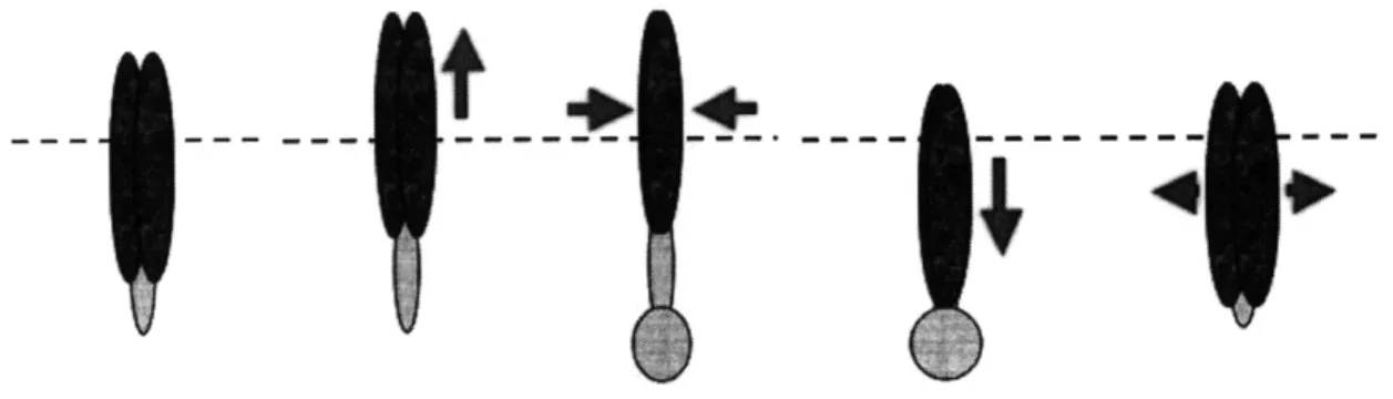
Razor clams burrow by using a series of four motions. A clam begins with its foot partially expended and shell relaxed. Then, the clam begins to extend its foot into the substrate, pushing the body of the clam upward slightly. The clam then rapidly contracts its shell to expand and anchor its foot deep into the substrat. Next, the clam pulls itself downward by retracting its foot. Finally, the clam allows its shell to open again in
preparation to repeat the pattern and inch itself further along [7]. Figure 1 details the steps of the razor clam digging process.
Figure 1: Step by step diagram of the razor clam digging motions. The calm probes and anchors its foot before pulling itself downward into the substrate. While the general pattern of motions for razor clam digging has been observed, a more detailed understanding of the timing of these motions is necessary for future research and development of robotic anchors.
1.3 Review of Existing Technology
Existing angle sensors would not be ideal for measuring the angle of a razor clam's shell versus time as it digs because most available angle sensors measure the relative rotation of a shaft, not the angle between two bodies. Also, many of the angle sensors on the market employ techniques that would be unsuitable for use in saltwater environments, such as optical light refraction, electrical induction, and thermal conduction variation and most of these sensors are also simply too large or too heavy to be attached to a razor clam [8].
A new sensor had to be developed that would not only be capable of fitting on a clam to measure the desired angle, but appropriate for use in harsh saltwater conditions without compromising accuracy. This paper outlines the process taken to design such a device.
CHAPTER
2
Design Conceptualization
2.1 Functional Requirements
Several functional requirements governed the design process for the angle-sensing device. The first of these requirements was that angle sensor was able to measure the angle between the two halves of a clam's shell, which ranges from 0 to 20 degrees (0 to 0.35 radians), accurately and reliably [7]. The sensor therefore needed to be able to operate in a predictable and repeatable manner when placed on a clam, without being over constrained. This would also mean that the device could be accurately calibrated so that data collected by the sensor could be easily interpreted.
Since razor clams live in salt water estuaries, it was also important for the device to be portable and salt water compatible, meaning that the measuring components had to be able to work underwater, and that the device itself would not be damaged by contact with salt water. Also, the sensor had to be able to attach to a clam securely, even when wet, but ideally be able to be removed and reused.
Finally, the sensor was required not to hinder the digging motions of the clam and thereby influence the data that it collected. The device therefore had to allow a clam to freely open its shell, and create minimal additional axial drag resistance on a clam's downward progress. The average razor clam is able to produce a moment of 0.27468 Nm (2800 g*cm) by pulling inward on its shell [7]. Therefore, even with a sensor attached, a clam had to still be capable of closing its shell using no more than 0.27468 Nm of torque. The axial drag force on a clam digging downward through a fluidized bed is proportional to the frontal area of the clam that is presented to the media as it digs, as shown by
F, = CD pv 2A, , (1)
where FD is the drag force on the clam, CD is the drag coefficient, p is the density of the fluid, v is the velocity of the clam, and the Aclam is the frontal area of the clam [2]. Adult razor clams usually have frontal areas ranging from approximately 0.001399 m2 to 0.001844 m2.
For the case of a clam with an angle sensor attached, the coefficient of friction was assumed to be the same as for a clam without a sensor. The clam was also assumed to be able to move with roughly the same velocity when an sensor was attached, given the functional requirement for the device of not hindering the motion of the clam's shell was met. These assumptions imply that the ratio of the drag forces produced by a clam with a
sensor attached and a "naked" clam and is primarily dependent on the ratio of the frontal area of the two clams, as shown by
FD sensor O.5C Y 2 (Acam + Asensor) (Acam + Asensor)
2 (2)
FD 0.5Cp 2Aam Aclam
where Asensor represents the additional area that the sensors add the to frontal area of the clam, which may or may not be equal to the entire area of the sensor itself. The device would ideally produce no more than a ten percent increase in the drag force on the clam, leading to a desired area ratio of no greater than 1.1.
2.2
Strain Gauge Angle Measurement Strategy
Waterproof strain gauges were chosen as the method to measure the angle of a clam's shell without being compromised by contact with salt water. The special gauges selected come sealed in a watertight epoxy resign so that they can read small strain changes even underwater without shorting.
Another reason for using a strain gauge as the measuring component of the device was that a strain gauge attached to a beam can very precisely measure the small strain that occurs as a result of bending of the beam. Then, if the distance between the ends of the beam, and therefore its degree of curvature, is a function of the angle of a clam's shell, it is possible to calculate that shell angle by reading the strain observed by the gauge. The sensing device was therefore designed to create a relationship between the strain read by the gauge and the angle of the clam's shell in a deterministic and controlled way.
Strain gauges, even those with waterproof backing, also offer a low-cost solution to the angle measurement challenge, enabling the sensing device to be made very cost-effectively.
2.2.1 Additional Strain Gauge Design Constraints
The decision to use strain gauges to indirectly measure the angle of the clam's shell created a few more constraints on the design of the device. Even though the gauges are protected by epoxy resign on the top, they are exposed on the bottom because the gauges
themselves must be in contact with the surface of the object for which they are measuring strain in order to give accurate readings. Strain gauges are also fairly fragile and can be bent or forced off the epoxy resign backing if subjected to curvature higher than
approximately 420 m1. So, since the fragile gauges are not protected on all sides, and can be easily damaged, it was essential that the portions of the sensing device in contact with the strain gauges not be put through excessive curvature.
Another constraint brought up by the inclusion of strain gauges in the design was the maximum strain that the gauges could withstand. If the particular strain gauges used are attached to a surface that experiences more than 3% strain, the gauge can be permanently damaged [6]. Therefore, the dimensions and shape of the measurement device had to be
developed in a way that was mindful of the strain that the areas near the strain gauges would experience and ensure that the strain in these areas would not exceed 3%. Finally, the strain gauges have wires coming out of the backing that carry the voltage
output signal from the gauges to a recording device or computer. Space for these wires also had to be incorporated into the design of the angle-sensing device.
2.2.2 Thermal-centric Design
A simple beam with only one strain gauge would be sufficient to measure the strain in a beam, and therefore, the angle of the clam's shell, but a double strain gauge design was
developed to eliminate error caused by thermal expansion and contraction of the beam due to temperature changes during use. Temperature effects can cause a beam to experience extra strain, thus the strain output of a single gauge would contain both the strain due to thermal expansion or contraction and the strain induced by bending the beam. This effect can be shown by looking at the deflection of a beam before and after a temperature change. The area moment of inertia of a rectangular beam is given by
I= - bh3 , (3)
12
where b is the width of the beam and h is its thickness [3]. When the beam undergoes a change in temperature, the moment of inertia becomes
IA = 1 (b + baAT)(h + haAT)3 , (4) 12
where a is the coefficient of thermal expansion and AT represents the change in
temperature. When a cantilever beam is subjected to a force on its unsupported end, the maximum deflection of the beam is given by the beam bending solution,
FL3
6 = (5)
3EI'
where F is the force on the beam, L is the length of the beam, and E is its Young's modulus [10]. When the beam changes temperature, the maximum deflection equation becomes
A F(L + LaAT)3
lAT (6)
3E,
For ultra high molecular weight polyethylene, which is the polymer that the measurement device was manufactured from, temperature changes of up to twenty-five degrees
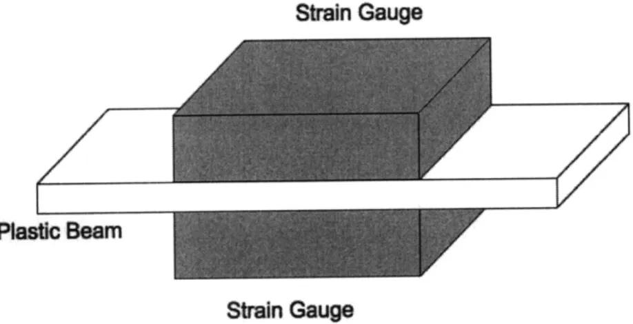
Using two strain gauges in conjunction with a Wheatstone bridge can eliminate this thermal error. As shown in Figure 2, one strain gauge is placed above the beam and one
is attached below the beam, and the gauges are wired as two adjacent legs of the Wheatstone bridge.
Strain Gauge
Plastic Beam
Strain Gauge
Figure 2: Diagram of a thermal centric beam configuration.
A Wheatstone bridge is a circuit consisting of resistors which can be used to can be used to subtract two voltages. A schematic of a Wheatstone bridge is shown in Figure 3. When a beam is bent with a positive moment, the upper half of the beam will see a negative strain while the bottom half of the beam will experience a positive strain. If the beam undergoes thermal expansion however, both the top and the bottom of the beam will see a positive strain. If a Wheatstone bridge is used to subtract the voltage outputs of the two strain gauges, the strain due to thermal expansion will cancel out [6].
Figure 3: Schematic of a half and one below, to eliminate the
Wheatstone bridge using two strain gauges, one above the beam tensile strain in the beam. E is the excitation voltage and Ae is the
strain difference [6].
2.3
Initial Concepts
The next task in the development of the angle sensor was to design a to bend a beam with strain gauges attached by the closing of a clam's shell. Initial designs for a device
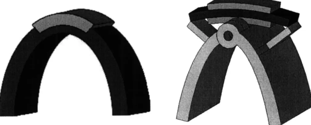
incorporating the strain gauge angle measurement strategy included simple flexible strips, compliant mechanisms, and complex combinations of composite beams and piano hinges. Figure 4 shows a couple of early design renditions.
Figure 4: A couple of initial ideas. Flexible beams are represented in blue, strain gauges in waterproof encapsulate are represented in orange, and
rigid components are depicted in grey.
2.4 Development of the Alpha Prototype
The functional requirements were used to refine the initial concept ideas into an alpha prototype design. The shape of the prototype, as seen in Figure 5, included two main sections, a flexible bridge-like region where the strain gauges could be attached, and legs that could be secured to a clam's shell using waterproof tape, allowing the clam to bend the bridge as it closed its shell. The shape of the legs was designed to snuggly fit the contours of a clam's shell. The hinges were changed to flexural hinges so that the device would be easy to machine and the bridge section was kept as close to the central hinge as possible while leaving room for a strain gauge to be attached to both the top and bottom
of the crossbeam [4].
Figure 5: The shape of the alpha prototype went through several design iterations to better fit the curve of a razor clam's shell.
A simple piece of flexible material may have been able to attach two strain gauges to a clam to roughly measure shell angle, but this two-part design was chosen to make the
angle-measuring process more repeatable. The central hinge mirrors the hinge of the shell and directs the bending of the bridge in a predicable and controlled manner. Another reason this slightly more complicated design was chosen was to protect the strain gauges from undergoing excessive curvature.
Another important aspect of the alpha prototype is that the neutral position of the bridge section, which becomes a composite beam when strain gauges are attached, was designed to coincide with the device's open position. This decision was made to minimize device
interference with clam motion. Razor clams are only able to pull their shells inward, not push them outward. Therefore, the angle sensor could not put resistance on the clam's
shell as it was opening, only when the clam was pulling its shell closed. With the neutral position of the composite beam occurring in the open position, the clam only had to
expend effort to bend the beam to close the device. 2.4.1 Alpha Prototype Critical Dimensions
As previously stated, the dimensions of the legs of the alpha prototype were chosen in an effort to match the shape of a clam's shell. For the bridge section, however, once the general shape had been decided, the ratio of the stiffness of the support beams, or "A beams" to the stiffness of the sections of crossbeam not in contact with strain gauges, or "B beams" was used to determine the important dimensions. The stiffness of the "A beams" was desired to be at least ten times greater than the stiffness of the "B beams" so that when the device was pulled closed the "A beams" would not flex, but simply transfer a moment to the crossbeam and the strain gauges. This made the deflection of the
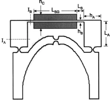
crossbeam easier to model, thereby making it easier to predict the strain that would be measured. The critical dimensions of the bridge section are labeled in Figure 6.
Figure 6: Diagram of the top view of the alpha prototype with critical dimensions of the bridge section labeled. The grey rectangles represent strain gauges with
waterproof backing. Dotted lines indicate cross-sections where moments of inertia were calculated for both the "A beam" and the "B beam". The definition of stiffness for a beam is given by
k =- (7) 6
where F is force and 8 represents deflection [3]. The "A beam" was modeled as a cantilever beam and Equation (5), the bending solution for the maximum deflection of a cantilever beam which has a force applied to is unsupported end was used to gain another relationship between deflection and force,
6 FL3
3EI
Substituting into Equation (7) yields a stiffness equation specific to a cantilever beam with a force on the end. The negative sign canceled out due to the direction of the force to give
3El
k = (8)
Then, in order to satisfy the condition of 10kB < kA the inequality
10 " < A
LB LA
must be true. The definition for moment of inertia was then substituted into the inequality and the expression was simplified to gain
h3 h3
10 B A (9)
The dimensions of the bridge section of the device were then selected so that this condition would hold true.
2.4.2 Bench-level Testing of Alpha Prototype
Once the dimensions of the alpha prototype were decided upon, an initial version of the device was manufactured on a water jet machine so that bench-level tests could be conducted on a live razor clam in its native estuary habitat to determine if the clam could dig properly with a sensor attached. An actual strain gauge was glued to the top of the bridge section, but a strip of rubber with similar material properties had to be substituted for the bottom strain gauge because accommodations had not been made for the wires leading out of the lower strain gauge. The legs of the device were attached to the shell of the clam using waterproof foam tape, as shown in Figure 7. The clam that was found at the estuary had a shell that was a slightly different size than the shell that was used to design the shape of the sensor however, making the fit of the device less than ideal.
Figure 7: The alpha prototype device attached to a razor clam. The contour of the legs of the sensor did not fit the curve of the clam's shell perfectly, so the placement of the device had to be
adjusted, leaving a gap between the shell and the sensor.
To determine if the sensor hindered digging motions, two clams, one without a device and one with a device attached were placed side by side and allowed to dig, as shown in Figure 8. The clam without a sensor began digging first, but the clam with the sensor quickly caught up and managed to burrow itself entirely into the substrate before the "naked" clam. Once it reached the level of the soil however, the clam was able to scrape free of the sensor due to the relatively large surface area of the alpha prototype.
Figure 8: A race between a clam without a sensor attached, and one with a sensor on it. 8a) Initially, three were clams placed horizontally, 8b) The clam without the sensor stood up and
began digging first, 8c) The clam with the sensor quickly followed, 8d) The clam with sensor took over the lead, 8e) The clam with the sensor reached a depth where the sensor touched the soil, 8f) The clam with the sensor continued to dig downward, scraping itself free of the sensor. The results of the bench-level testing at the estuary proved that the angle sensor did not produce excessive resistance on the motions of the clam, since the clam with the sensor attached was able to dig as quickly as a clam without a sensor. The large surface area of the device, as well as the difficulty in fitting the shape of various calms however, implied that many improvements could still be made to the design.
2.4.3 Limitations of the Alpha Prototype
Testing on live clams at the estuary pointed out several failings of the alpha prototype sensors. The variation of clam sizes presented a challenge in fitting the sensor to the outside of the shell properly. Ideally, the sensor would hug the shell closely, with the center hinge of the device as close to the axis of the clamshell's hinge as possible.
However, the curved shape of the device did not match the curve of the shell exactly and the sensor had to be attached with a gap between the shell and the sensor to ensure secure tape contact. This gap created an additional, undesirable level of geometric abstraction between the measured quantity and the actual angle of the clam's shell.
Also, the alpha prototype clearly produced too much extra axial drag force on the clam, as emphasized by the clam being unable to continue digging below the level of the soil with the sensor still attached. The area ratio, given by Equation (2), for the alpha
prototype ranges from 1.196 to 1.258 depending on the size of the clam, higher than the desired 1.1. The frontal area of the device clearly needed to be reduced to decrease the magnitude of the drag force.
CHAPTER
3
Design Refinement
and
Development of the
Beta Prototype
The angle-sensing device was redesigned into a beta prototype that conserved the desirable compliant hinges and a flexible bridge for the strain gauges of the alpha prototype, but greatly reduced the amount of addition axial drag force that the device creates on the clam and improved upon the device's ability to attach securely to differently sized clams, thereby producing more accurate angle measurements.
3.1 Beta Prototype Improvements
The alpha prototype produced a great deal of drag force on the clam because the sensor was attached to the outside of the clam's shell, meaning that the entire cross-sectional
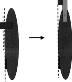
area of the sensor was added to the frontal area of the clam. The design was modified for the beta prototype to utilize aluminum extenders to allow the device to be secured so that the sensor itself sits almost entirely within the footprint of the clam. The relocation of the sensor between the alpha and beta prototypes is depicted in Figure 9.
I i
Figure 9: The alpha prototype was positioned outside of the footprint of the clam. For the beta prototype, the device was moved to the space above the clam to reduce
drag and to improve measurement accuracy. The blue line runs through the central hinge of the alpha prototype, which does not coincide with he red line, which indicates the axis of the clam's hinge. For the beta prototype, these two hinge
This relocation of the sensor drastically reduced the drag force on the clam due to the sensor. For this configuration the area ratio, given by Equation (2), ranges from 1.023 to 1.058, depending on the size of the clam, which is well below the desired 1.1.
Relocating the sensor to the area above the clam also helped the device in coping with different sizes of clams. The inside contour of the alpha prototype needed to fit the curve
of a clam's shell very closely for the tape to come in contact with enough of the shell to produce a secure fit. The legs of the beta prototype however, fit perfectly into the rounded extenders regardless of the size of the clam, as shown in Figure 10. The positions of the extenders themselves can then be adjusted slightly to compensate for
shell size. Another advantage of the extender method is that the extension pieces are placed vertically, so that more tape can be used over a greater surface area of the clam,
ensuring that the tape will stick properly.
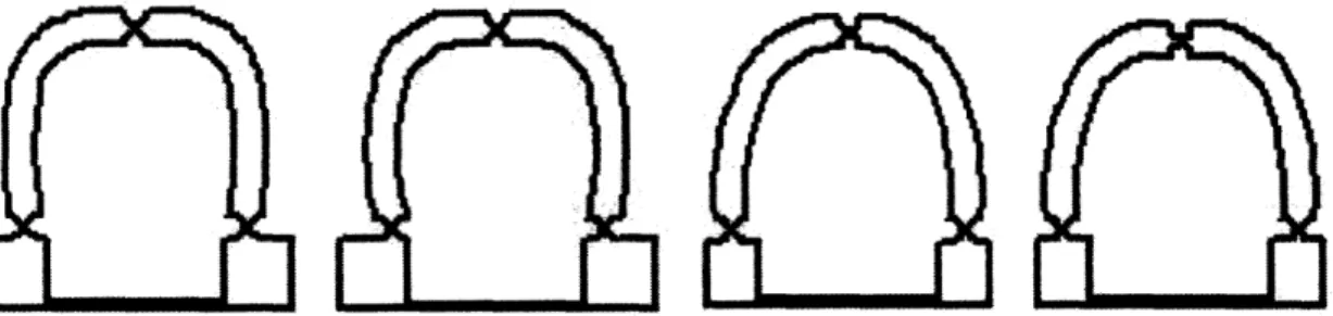
Figure 10: Progression of the shape of the beta prototype. The curves of the legs evolved to match the contour of the aluminum extenders and the overall shape was redesigned to better fit
within the footprint of the clam's frontal area.
Finally, the extender method of attaching the sensor to the clam allows the central hinge of the device to be lined up directly on the axis of the clam hinge. Aligning the hinges on the same axis greatly increases the accuracy of the angle measurement because it reduces the geometric error between the actual shell angle and the measured quantity.
3.2 Beta Prototype Critical Dimensions
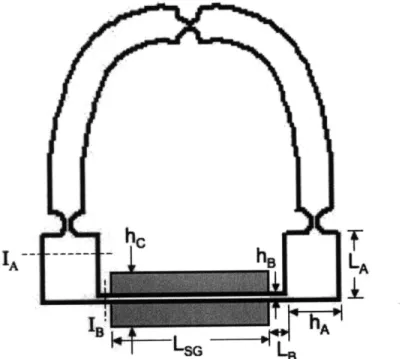
The flexible bridge section of the beta prototype where the strain gauges attach is very similar to that of the alpha prototype, as can be seen in Figure 11. The dimensions had to be reduced however, to ensure that the device would fit inside the frontal area footprint of
the clam. Once again, the ratio of the stiffness of the "A beam" to that of the "B beam" was used to determine the critical dimensions for the bridge section. For the beta
prototype however, the stiffness of the "B beam" was set to be only 5 times the stiffness of the "A beam" because the overall device was smaller.
IA
h
LAFigure 11: Diagram of the beta prototype with dimensions for the bridge section labeled. Dotted lines indicate cross-sections where moments of inertia
were calculated for both the "A beam" and the "B beam".
The dimensions of the legs of the device were dictated by the goal of fitting within the footprint of the clam, as well as the curvature of the aluminum extenders.
3.3 Compatibility with Clam Abilities
The beta prototype was able to meet the functional requirement of not hindering the motion of the clam by requiring a small amount of torque to close the device. To calculate the moment that a clam is required to produce on the device, the effective bending stiffness for the bridge section with the strain gauges attached was first determined and used to discover the force need to close the device. This closing force
was then multiplied by the moment arm of the device to calculate the required moment. 3.3.1 Effective Bending Stiffness
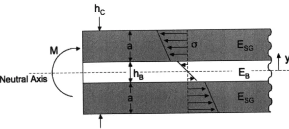
A slice of the composite section of the bridge portion of the sensor was looked at in order to calculate the effective bending stiffness for the composite section. Figure 12 shows the slice of beam that was analyzed.
h
M
Neutral Axis
Figure 12: Diagram of a slice of the composite beam with being moment applied. Strain gauges are shown in grey and the white represents the plastic crossbeam
of the bridge. The beam has a depth, b, into the page.
The first step in the analysis was to look at the definition for radius of curvature for a beam [3].
1 M 1 M(10)
PR El
This equation was then manipulated to yield an expression for the quantity EI, called the bending stiffness of a beam.
EI= Mp, (11)
The next step was to use the integral definition for the moment on a beam to evaluate the composite section,
h/2
M f (-oy)dA , (12)
-h/2
where o represents the stress inside the beam, and y is the distance from the neutral axis [10]. Substituting
dA = bdy, O = Ee, and E = E
into the equation gives an integral containing variables from the bending stiffness equation,
h12 bE2
This integral was expanded to account for the different material layers of the beam and multiplied by pR to give
MPR = (El)effective
-t/2 t/2 t/2+a
= f(bESG Y2)dy+ f(bE y2)dy+ f(bESG Y2)dy
-(a+t/2) -t/2 t/2
This equation was then evaluated and simplified to produce an equation for the effective bending stiffness of the composite beam,
(EI)i = bEs 3 + 2t + t3 + bE, .
efcte
3
2
12
(13)3.3.2 Required Moment to Close Sensor
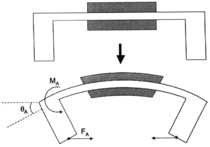
A couple of assumptions were made in the process of calculating the moment required to close the device. First, the stiffness of the compliant hinges was assumed to be negligible compared to the stiffness of the composite bridge section of the device. The hinges were designed to bend easily and therefore were assumed to offer negligible resistance to closing the device. Second, the aluminum extenders were assumed to be rigid because aluminum has a much higher stiffness than the plastic of the device. Therefore, the extenders were assumed not to flex during closing of the device.
Due to these assumptions, the bridge section was focused on during the calculation of the moment required on the device. The composite bridge was modeled as being bent about
its neutral, open position, by an inward force on the "A beams" that transferred a negative moment to the composite section. Figure 13 shows this bending action.
Figure 13: Diagram showing the bridge section of the device being bent from its neutral position. The moment on the crossbeam, MA, produces a deflection angle of OA.
The negative moment on the crossbeam of the bridge creates a deflection angle, which can be calculated as the sum of the deflection angles of the two individual sections of the crossbeam, the composite beam with deflection angle 01, and the "B beam" with
deflection angle 82. Also, the inward force on the "A beam" creates a horizontal
displacement of 8x of the end of the beam. The bent half of the bridge section is depicted in Figure 14.
01,
I,
\
Figure 14: Diagram showing the summation of deflection angles at end of the beam. The force on the bottom of the "A beam" creates a horizontal deflection of 8,x.
These deflection angles were determined using the solution for the deflection angle of a cantilever beam,
ML
max EI (14)
where M is the moment on the beam, L is the length modulus, and I is the beam's area moment of inertia
MA LSG
o
2(EI)
effectiveand for the "B beam" section
92
= MALBEB
lof the beam, E is the Young's [3]. For the composite section
(15)
(16)
The two deflection angles were then added together to produce an expression for the total deflection angle of the crossbeam,
OA = 01 02 = MA SG2(E) + 2(EI) effective
LB EBIB)
Solving Equation (17) for the moment on the crossbeam yielded
OA
MA =/
(17)
(18)
The moment on the crossbeam could also be represented as
MA = FALA,
which was combined with Equation (18) to give an equation for the inward force on the "A beams", M 6
FA=
MA A (1 LA LA LSG + LB 2(EI) E B S effectiveNext, another equation was needed for the total deflection angle of the crossbeam. Assuming small values of OA,
bx = LAOA ,
which can be solved for the deflection angle,
OA = x (2
LA
Equation (20) was then substituted Equation (19), but an expression for the horizontal displacement was still needed to complete the force equation,
FA / 6 (2
9)
0)
.1)
The geometry of the device was examined to find a way to represent the horizontal displacement of the tip of the "A beam" as a function of the angle of the clam's shell. When the clam exerts a force, FA, on the leg of the device, the line connecting the lower hinges and the central hinge, labeled as R when the device is open, swings inward to the
dotted red line position. When the clam is fully closed, this length is along the black dotted line. The angle was then defined as the fixed angle between the line
corresponding to the closed position and a vertical centerline. Figure 15 shows a top view of the sensor with R, H and labeled.
Clam
is closed
Figure 15: Diagram showing three more dimensions of the device, R, H, and 4. Figure 16 shows a more detailed view the triangle formed by the dimensions R and H, and the horizontal line of FA.
'I I Si 'I / I, d1
*+Q 8)
Figure 16: Diagram showing the angles involved in the triangle formed by the dimensions R and H, and the horizontal line of FA
S= Rsin + - Hsin + , (22 which could then be substituted in the force equation to give
SRsin + - Hsin + (23
FA - (23
L2 LSG LB
L 2( EI)effective I
Equation (23) was then multiplied by the lever arm of the device, H, to acquire an equation for the moment required to close the device,
M F
H Rsin + -Hsin+ clam (2
MA FAH (24
L LSG + ,
2(EI)ff EB IB
which is a function containing only known quantities and the angle of the clam's shell. The average clam can pull its shell inward with a moment of 0.27468 Nm (2800 g*cm), and the maximum moment needed to close a clamshell with a device attached is 0.1022 Nm, which is only 37.2% of what the clam is capable of. Figure 17 shows a graph of the moment required on the sensor as a function of the angle of the clam's shell.
0.25 0.2 0.15 0.1 0.05
)
)
0.05 0.1 0.15 0.2 0.25 0.3 Angle of Clam Shell (radians)Figure 17: The moment required to close the sensor decreases as the angle of a clam's shell increases.
•. • ? ..; g i
Maximum moment clam can
produce:-... ....
o ... .
.
.
.
.
.
.
.
.
.
.
.
..
.
...
...
...
...
i
.
...
.
...
i...
...
..
.
.
.
.
.
.
.
.
.
.
Required moment on sensor
.. ...I .. ... ... ... i.
The moment required to close the sensor decreases as the angle of the clam's shell increases, meaning that the clam will always be able to pull the sensor closed. Therefore, the sensor does not hinder the motion of the clam's shell.
3.4 Compatibility with Strain Gauge Constraints
3.4.1 Maximum Measured Strain
Simple constitutive and kinematic equations for strain,
O" -y
E = , and
E-E PR
and Equation (10), the definition of the radius of curvature, 1 M
PR El
were combined to gain an equation for the strain inside the composite section of the crossbeam of the device [3]. The effective bending stiffness was used in the equation to account for the fact that the beam is made of two different materials,
E = - M (25)
(EI)etjctive
Substituting in the distance from the neutral axis of the strain gauges, hB/2, and taking the maximum strain at the point when the clam has fully closed its shell, the maximum strain experienced by the strain gauges during the use of the sensor device was determined to be
E M B = _.1.4% ,
m 2(EI)eetive .=0
which is less than half of the maximum strain that the gauges are capable of measuring. Also, if the measured strain is plotted versus the angle of the clam's shell, a clear, linear pattern can be seen that decreases as the angle of the shell increases. This shows that the strain gauges will not experience greater strain than they can measure when the device is in normal use. Figure 18 shows a graph of the strain measured by the upper strain gauge as a function of the angle of the clam's shell.
3.
2.
0.
0.05 0.1 0.15 0.2 0.25 0.3 0.35 Angle of Clam Shell (radians)
Figure 18: Graph showing that the strain measured by the gauges will always be below the maximum strain that the gauges can measure.
3.4.2 Maximum Strain Gauge Curvature
The curvature of a beam behaving in a linear-elastic manner, K, can be stated as the reciprocal of the radius of curvature, PR [3],
1 M
P = El
PR El
and the maximum curvature of the crossbeam, and of the strain gauges as well, occurs when the clam has fully closed its shell, implying
Km
MA
m
(EI)effectie
cm = 0(26)
= -46.9m-'
Based on the results of a controlled test, a strain gauge begins to wrinkle off its backing and become damaged at approximately -420 m', meaning that this design will not cause the strain gauge to undergo enough curvature to cause damage.
3.5 Relationship Between Measured Strain and Shell Angle
In order for the device to be used as an angle sensor, a relationship between the strain measured by the gauges and the actual angle of the clam needed to be established. Equation (25) was used to express the strain at the strain gauges.
Maximum strain a gauge can measure : 5
5
-!...
. . . ,I . .,i .. ... -i
E= = MAhB 2(EI)effective
where
MA = FALA
Only taking the strain seen by the strain gauge on top of the bridge,
(27)
which can be solved for the angle of the clam's shell in terms of the measured strain,
Oclam = 2 sin-' 2ELA (EI)effective
com
Hh,
LSG _B + in +
2(EI)ffective EBlB H (
3.6 Material Selection
Once the compliant design was decided upon, it was important to select a material out of which to make the device that would accommodate the motion flexural hinges. The very thin sections of the hinges themselves needed to be able to go through a fairly high curvature without snapping, approximately 33.5 m' when the clam's shell is fully closed. A definition for the moment on the beam can be found using the equation for normal bending stress as a function of distance from the neutral axis of a beam. In this case, the stress is taken to be the maximum stress the beam can withstand before yielding, Oy, which would occur in the location on the beam furthest from the neutral axis [3].
MI--r - - M =21 (29)
I h
Substituting this moment definition into Equation (26), the equation for curvature produces a new expression the curvature of a beam,
21y 1 , 2
h EI Eh
(30)
The value of the quantity (2/h) is determined solely by the geometry of the beam. For the flexures, the thickness, h, is very small, making the quantity (2/h) a fairly large number. The flexures needed to be made out of a material that has a high yield strength to
Young's modulus ratio, however, to ensure that the value for the curvature through which the hinges could move in an elastic manner remained high.
A material selection chart, given in Figure 19, showing Young's modulus versus yield strength indicates that polymers are ideal choices for materials with high values for
(oy/E). 1000! 100' wJ 10 "0 E Cu I _=" : CIe
Metas and poyNms: yield strength
Ceams and gisses: MoR Elastomes tensle tear eng
ceoaile: tansb lawe stelj
Con atA
0.01
0.1 1 10 100 1000
Strength, of (MPa)
Figure 19: Chart showing materials organized on a graph of Young's modulus versus Yield Strength. Polyethylene is shown boxed in blue [1].
Not all polymers would be acceptable materials for making the compliant device, however, because the strain gauges must be glued to the surface of the device. Also, the
action of attaching the device to a clam can sometimes briefly put the hinges into a higher curvature than normal use, which can bend the hinges beyond their elastic limit.
The alpha prototype was made from acrylonitrile butadiene styrenepolymer, or ABS, which has a high yield strength to Young's modulus ratio of 0.01056, but a small value
for the percent elongation at break of only 1 to 5% [5]. This small value for percent elongation meant that the thin flexures in the hinges would snap very soon after reaching their elastic limit. The compliant device was therefore very fragile and difficult to attach
to clams without breaking the hinges. A material with a higher percent elongation at break would instead plastically deform slightly under such conditions, keeping the hinges intact.
To incorporate all three desirable material properties of high yield strength to Young's modulus ratio, waterproof glue compatibility, and high elongation at break, the material selected for beta prototype was ultra high molecular weight polyethylene, or UHMW-PE. UHMW-PE has a yield strength to Young's modulus ratio of 0.05096, good glue
compatibility, and a very high 300% elongation at break, making it an ideal material for manufacturing the angle sensors [5].
3.7 Bench-level Testing of Beta Prototype
Initial testing with the beta prototype was done in a lab setting to gain insight as to whether functional requirements were practically being met by this design. A fully assembled sensing device was aligned with the axis of a clam's hinge, and secured with waterproof tape. The clam was then allowed to dig into glass beads to simulate the soil found at the clam's native estuary environment.
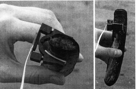
The attachment procedure for the beta prototype was slightly more complicated than that of the alpha prototype. First, the sensor was fitted with the aluminum extenders, which had been prepared with waterproof foam tape, as shown in Figure 20.
Figure 20: The beta prototype with extenders attached. Notice the good tape contact between the extenders and the device, as well as the small
hole for the wires of the lower strain gauge in the right "A beam".
The next step in aligning the device was to secure the extenders to the clam. A large, straight tongue depressor, shown in Figure 21, was used as a guide to ensure that the
hinge axis corresponded with the line running through the central hinge of the angle sensor.
Figure 21: Clam with beta prototype attached. The tongue depressor was held in place with a rubber band so that it would remain stationary
throughout the alignment process.
As predicted, once fully attached, the beta prototype fit almost entirely within the frontal area footprint of the clam, as seen in Figure 22.
Figure 22: Top view of the beta prototype secured to a clam. Notice that the device is not interfering with the small amount of clam sticking out of the top of the shell. Finally, the sensor-equipped clam was placed in a graduated cylinder with glass beads replicating the estuary soil, as shown in Figure 23. The clam seemed to be able to maneuver its shell well, and did not appear to be hindered by the device.
Figure 23: The clam with a beta prototype angle sensor digging into the glass beads. One small area for improvement for the beta prototype was the shape of the extenders, as the shell of a razor clam has a slight taper at the top that was not originally accounted for in the extender design. If the shape of the extenders is altered to fit the taper of the clam better, they could be secured to the top of the clam more securely with the waterproof tape, which will increase the accuracy of the measurements taken with the sensor. Bench-level testing showed positive results for the beta prototype, however because the device was able to be easily attached and aligned on the clam, and did not seem to produce undue resistance to the clam's movements.
CHAPTER
4
Calibration
As with any measurement device, the angle sensor needed to be calibrated before it could be used to accurately take data. A calibration diagram was developed for this purpose and is shown in Figure 24. The angle labels for each guideline correspond to the angle
between the two halves of the clam's shell that would move the sensor to the position where both legs of the device would fall on the given guideline. For example, to measure the voltage output for a ten-degree clamshell angle, both of the legs of the device must be touching their respective ten-degree guidelines.
I
/
+\/0
1
00
20
20
Figure 24: Diagram that was used to calibrate the beta prototype angle-sensing device.
The angle sensor was placed on the diagram, with the inner comers of the legs just touching the guideline at each desired angle and the voltage output of the strain gauges was recorded at each angle position. Once voltage readings had been taken for several angles, a calibration relationship was derived. Figure 25 shows the experimental calibration data plotted with the derived linear fit line.
I I l - -... ... .... ... ... ... ... .... ... ...
.
.
.
.
.
.
.
.
.
.
.
.
.
.
.
.
..
.
.
.
.
.
.
,.. .. ... . .. .! .. ... ... .. . . .. . ' " . - . : ... ... 1 i o . iv"0"'""~ :://"''"':' - ' 40 535 E 30 ( 25 EL 20 (D 15 10 5 I ... ... .. .. .. .. ... . .. ... .. .... .. .. .. ... ... .. ... .. .. .. .. .. .. .. ... .l...,., , , ...- .. .. ... .. .... ..., 0.05 0.1 0.15 0.2 0.25 Angle of Clam Shell (radians)0.3 0.35
Figure 25: Graph of the recorded voltage values, shown as diamonds, and the linear fit, shown as a dotted line. Three iterations of data were taken, with the closeness of the values showing that
voltage output of the device is reliable over the range of measured angles. The linear fit line equation used was y=106.73x+5.23.
The calibration data showed that the sensor produces precise, reproducible angle
measurement readings. The linear calibration relationship also fits the data nicely and can be used to convert voltage readings into radians. The results of the calibration experiment show that sensor is now ready for use in measuring the shell angle of a razor clam in real-time. I... I-.. 0 Ab,
-""''
t I.;.
Chapter
5
Conclusion
The angle measurement devices designed as a part of this thesis have been theoretically proven, and experimentally validated to fulfill all of the functional requirements for a portable, reliable, saltwater compatible angle sensor for use in collecting data about the precise digging motions of the razor clam. The device can detect the angle change of a clam's shell and relay that information as a voltage signal, without thermal error. The angle sensor also produces minimal resistance to the clam's movements, and is easily attached and aligned.
The sensor is now calibrated and ready to be used to gather real-time angle data for live clams digging in estuary substrates. This powerful information can then be used to develop new anchoring technologies for use in traditional and emerging marine applications.
Design Drawing for Beta Prototype
R1 R8.962
Notes:
1) Dimensions in mm
2) Device is symmetric around center line shown
3) All hinges are composed of circular curves with Rlmm
A
References
1. Ashby, Michael F., "Materials Selection in Mechanical Design," Pergamon Press, 1992.
2. Brisson, J., "Thermal-Fluids Engineering II," 2008.
3. Hibbeler, R. C. "Mechanics of Materials," Pearson Prentice Hall, 2005. 4. Howell, Larry L., "Compliant Mechanisms," Wiley, 2001.
5. "Matweb, Material Property Data," < http://www.matweb.com/index.aspx > Automation Creations, Inc, 2009.
6. "Strain Gauge Connections and Bridge Circuits,"
< http://www.tml.jp/e/product/strain_gauge/bridgelist.html > Tokyo Sokki Kenkyujo Co., Ltd., 2009.
7. Trueman, E.R., "The Dynamics of Burrowing in Ensis (Bivalvia)," Proceedings of the Royal Society of London. Series B, Biological Sciences, Vol. 166, No. 1005, 1967.
8. "United States Patent and Trademark Office," < http://www.uspto.gov > USA.gov, 2009
9. Winter, Amos G., V, A. E. Hosoi, Alexander H. Slocum, Robin L. H. Deits, "A Machine Used to Investigate and Optimize Razor Clam-Inspired Burrowing Mechanisms for Engineering Applications," Massachusetts Institute of Technology, 2009.
10. Young, Warren C., Richard G. Budynas, Raymond J Roark, "Roark's Formulas for Stress and Strain," McGraw-Hill, 2002.