HAL Id: hal-02273929
https://hal.inria.fr/hal-02273929
Submitted on 18 Oct 2019
HAL is a multi-disciplinary open access
archive for the deposit and dissemination of
sci-entific research documents, whether they are
pub-lished or not. The documents may come from
teaching and research institutions in France or
abroad, or from public or private research centers.
L’archive ouverte pluridisciplinaire HAL, est
destinée au dépôt et à la diffusion de documents
scientifiques de niveau recherche, publiés ou non,
émanant des établissements d’enseignement et de
recherche français ou étrangers, des laboratoires
publics ou privés.
Cost-driven framework for progressive compression of
textured meshes
Cédric Portaneri, Pierre Alliez, Michael Hemmer, Lukas Birklein, Elmar
Schoemer
To cite this version:
Cédric Portaneri, Pierre Alliez, Michael Hemmer, Lukas Birklein, Elmar Schoemer. Cost-driven
frame-work for progressive compression of textured meshes. ACM 2019 - 10th Multimedia Systems
Confer-ence, Jun 2019, Amherst, United States. pp.175-188, �10.1145/3304109.3306225�. �hal-02273929�
Compression of Textured Meshes
C´
edric Portaneri
Inria, Universit´e Cˆote d’AzurSophia Antipolis [email protected]
Pierre Alliez
Inria, Universit´e Cˆote d’AzurSophia Antipolis [email protected]
Michael Hemmer
GoogleMountain View, California [email protected]
Lukas Birklein
Mainz University Mainz [email protected]Elmar Schoemer
Mainz University Mainz [email protected]ABSTRACT
Recent advances in digitization of geometry and radiometry generate in routine massive amounts of surface meshes with texture or color attributes. This large amount of data can be compressed using a progressive approach which provides at decoding low complexity levels of details (LoDs) that are continuously refined until retrieving the original model. The goal of such a progressive mesh compression algorithm is to improve the overall quality of the transmission for the user, by optimizing the rate-distortion trade-off. In this paper, we introduce a novel meaningful measure for the cost of a progressive transmission of a textured mesh by observing that the rate-distortion curve is in fact a staircase, which en-ables an effective comparison and optimization of progressive transmissions in the first place. We contribute a novel generic framework which utilizes the cost function to encode triangle surface meshes via multiplexing several geometry reduction steps (mesh decimation via half-edge or full-edge collapse operators, xyz quantization reduction and uv quantization reduction). This framework can also deal with textures by multiplexing an additional texture reduction step. We also design a texture atlas that enables us to preserve texture seams during decimation while not impairing the quality of resulting LODs. For encoding the inverse mesh decimation steps we further contribute a significant improvement over the state-of-the-art in terms of rate-distortion performance and yields a compression-rate of 22:1, on average. Finally, we propose a unique single-rate alternative solution using a selection scheme of a subset among LODs, optimized for our cost function, and provided with our atlas that enables interleaved progressive texture refinements.
CCS CONCEPTS
• Computing methodologies → Computer graphics;
KEYWORDS
Geometry compression, surface meshes, textures, multiplex-ing, adaptive quantization, progressive vs single-rate
Author’s version
1
INTRODUCTION
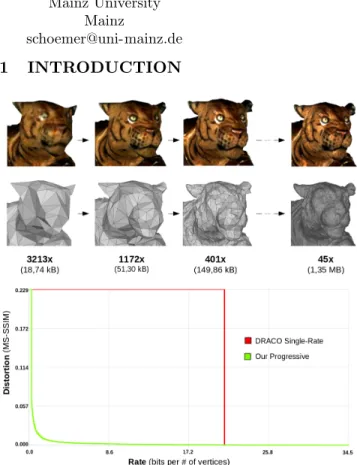
Figure 1: Progressive decompression of a textured surface triangle mesh. Top: key levels of details with their size and compression rate compared to the raw .obj file (texture data not included). Bottom: Dis-tortion against the bit consumption, in bits per ver-tex, where the number of vertices refers to the input mesh. Green is our progressive approach, red is the the state-of-the-art single-rate DRACO [4].
Surface meshes with textures are widely used for approx-imating 3D objects or scenes. When representing high res-olution objects, these meshes consume a large amount of memory and induce high workload on graphics pipelines. In addition, they generate large transmission latencies when used in networked environments. The increasing demand for visualizing and interacting with 3D objects in heterogeneous
graphics and networked environments has motivated research on compression of such data. This can be done by identi-fying and removing statistical redundancy or unnecessary or less important information, in a single-rate manner. The single-rate compression improves the transmission speed on high latency networks and reduces the storage footprint for portable devices. The recent initiatives such as the Draco open source library [4] confirm the renewed interest for prac-tical mesh compression methods.
Progressive textured mesh compression offers a means to encode the mesh geometry and the texture image (e.g. texture atlas) in stages, where each stage results in a refined precision of the various texture and mesh components (connectivity, vertex coordinates, texture coordinates). Every stage results in an increasingly faithful level of detail (LOD), considered in our context as a combination of a mesh geometry and texture data. This is specifically relevant for the transmission of high resolution models as the user on the client side can already display lower resolution levels of detail, without having to wait until the entire model is transmitted (Figure 1). Thus, it not only addresses limited bandwidth and storage but also ensures high scalability to heterogeneous networks with variable bandwidth and to devices with limited visualization performance.
While the levels of details can be single-rate encoded and transmitted to offer some level of progressiveness, in a real progressive compression algorithm the encoding of the next level takes advantage of the information already contained in the previous level. As a result, another motivation for progres-sive compression stems from the simplicity of providing only one file or stream to the client, which is more flexible and responsive for networked infrastructures than the single-rate alternatives.
In this context, reducing the latency requires optimizing the rate-distortion trade-off. While there is no universal con-sensus on the best way to measure distortion, we utilize a common screen-based error metric [6, 22] to capture the combination of geometry and texture.
In this paper we focus on progressive compression of surface meshes. More specifically, we seek for lossless connectivity compression for the finest level of detail and lossy geometry compression up to the user-requested quantization level for the vertex coordinates and the texture coordinates. While lossless connectivity is a hard constraint that prevents remesh-ing, this choice is justified by the fact that we assume that the input models are carefully designed and given to us only for compression, and not for mesh processing. We review next the closely related work, and refer to a recent survey [13] for a comprehensive review of a wider scope.
1.1
Previous Work
3D mesh compression has received some interest since the pioneering work of Deering [3]. The key principle behind most lossless compression approaches is the idea of transforming the input representation, so that the transformed data are
amenable to effective compression. The same principle com-monly applies to lossy compression, where bits are allocated to transformed components according to how perceptible they are. As textured meshes contain different pieces of infor-mation that are different in nature (connectivity, vertex and texture coordinates), different transforms are performed. For single-rate encoding the connectivity is often transformed into a sequence of symbols that records the canonical tra-versal of the connectivity graph: either few atomic symbols for the popular EdgeBreaker approach [17] or the degree of the mesh vertices [20]. The continuous attributes (geometry or texture coordinates) are commonly transformed into a sequence of integer residuals after global quantization and prediction derived from the connectivity traversal order.
Progressive compression requires converting the input mesh into a series of refinable levels of details, ideally a stream of fine-grain refinement operations. The approach pioneered by Hoppe [8] proceeds by iterative decimation and encodes the reverse atomic refinement operations that record where and how to refine the current level of detail. Several transforms were proposed to organize the operators into batches via canonical mesh traversal and the notion of independent set [1, 14]. Lee et al. pioneered an adaptive quantization approach for meshes with colored vertex attributes [11] that trades the quantization level for the mesh complexity, with improved rate-distortion trade-offs.
The related work is substantially narrower when focusing on textured meshes, and very few approaches multiplex mesh with texture refinement data. Yang et al. [23] first compress texture and mesh data separately, and represent them by a series of levels of details. Then, for each viewpoint they construct a so-called rate-distortion surface computed by measuring the visual quality of rendered images. An optimal path over this surface is computed via steepest descent. A hierarchical variant is proposed to deal with several view-points. Tian and Alregib [19] contributed a bit-allocation framework with capability to properly balance the bit rates for the mesh and the texture, so that the best visual fidelity is achieved during transmission. The main contribution is a fast quality measure for estimating the quality. Recently, Caillaud et al. [2] introduce another bit-allocation framework which multiplexes mesh and texture refinement data using a perceptually-based image metric, in order to optimize the quality of levels of detail. Beyond multiplexing, this approach can deal with general non-manifold polygon meshes, with arbitrary configurations of texture seams (discontinuities in the texture mapping). In addition, Lavou´e et al. [10] explore the optimal multiplexing of mesh and texture LODs (using Progressive JPEG) for the web, where both streaming and decompression are achieved via a parallel JavaScript/WebGL implementation. Finally, we note that the recent advances may have overlooked the work of Sander et al. [18] which focused on the generation of progressive meshes in which all meshes share a common parameterization, optimized to reduce stretch and deviation over the whole progressive mesh sequence. Albeit not specifically targeting compression, this
paper emphasized the importance of sharing a common tex-ture atlas across levels of details, which matches our intuition that sharing is an effective means to take advantage of the information already transmitted.
1.2
Positioning and Contributions
As preliminary work we performed a series of experiments to compare progressive compression with alternative approaches involving single-rate compression and multiplexing. To our knowledge, measuring the real advantage of progressive com-pression over such single-rate alternatives has not been carried out before. Our experiments reveal that (1) the advantage is smaller than the common belief, and (2) the definition of a cost function is required to measure altogether the quality of a series of levels of detail (LOD) and the bits required to encode them.
Our first main contribution is the introduction of such a cost function, referred to as “agony” in the sequel, which can be derived from an arbitrary used-defined measure of distortion.
Our second main contribution is a generic cost-driven framework for textured surface meshes, in which the afore-mentioned cost is used to choose between several reduction steps. Genericity comes (1) in terms of the reduction step type, as any reduction technique can be used and (2) in terms of the texture type, since it can handle any texture image parameterized with uv coordinates such as color maps, spec-ular maps or transparency maps (bumps maps containing normals would need another thread of work).
Finally, we contribute several novel ideas on the current implementation of each step that improve the rate-distortion performance, compared to previous work.
2
COST OF PROGRESSIVE
TRANSMISSION
The common criterion used for measuring the performance of a progressive compression algorithm is the rate-distortion (RD) “curve”. And in most cases a quick look suffices to determine whether an approach is better than the other. However, there seems to be no consensus in the literature for cases that are not that obvious, for instance, if two curves are really close, having multiple intersections with each other, etc.
The original motivation for progressive transmission stems from a user first approach. Specifically, the goal is to minimize the “agony” of the user defined as the “pain” the user suffers over time for either seeing nothing or being shown only a distorted version of the actual model. However, before we define the agony below the RD “curve”, we should make clear that this term is misleading. To our knowledge, we are the first to notice that the alleged RD “curve” is in fact a RD staircase, as the distortion remains constant in-between two levels of details (LODs). Thus, for a given set of N LODs, the agony is defined as : Agony =PN −1
i=0 Di× Ri+1, where distortion D0
denotes “nothing on the screen” and D1, D2, ..., DN denote
the distortions of the LODs, and R1, R2, ..., RN denote to
bit-rates consumed by each LOD. The better the progressive transmission of 3D data is, the closer the agony is to 0.
We remark that this cost is “unit invariant” in the sense that it does not matter for the comparison of different ap-proaches whether the given distortion metric is normalized or not. For this paper, we use the image-based perceptual metric detailed in [7] which compares image renderings of the textured mesh with MS-SSIM [22]. The actually measure of time (aka x-axis) can be the total number of bits, or bits per vertex or actual transmission time when the bandwidth is known. Throughout the paper, we consider the x-axis as the mesh compression performance in number of bits per vertex (bpv), where the number of vertices chosen as reference is the one of the input mesh. By default a rate expressed in bits per vertex is the average rate computed on all models shown by Figure 14.
Given this prerequisite, sending only the single-rate en-coded highest LOD ,which corresponds to a single point on the rate-distortion curve (DN= 0 and RN), induces a single
rectangle as the agony. Namely, the cost corresponds to the pain for seeing nothing D0 (high distortion measured by the
given metric), multiplied by the bit-rate it consumes to see the final mesh RN.
3
PROGRESSIVE COMPRESSION
FRAMEWORK
Our compression framework is devised to generate a series of levels of details (LODs) which yield a low agony.
3.1
Overview
The framework comprises the following main steps (see Figure 2):
(1) From the input mesh, we generate via mesh decimation a coarse mesh referred to as abstraction, while ignoring the texture content. Generate a new texture atlas from the abstraction and re-parameterize the input high resolution mesh onto the new atlas, so that the triangles of the abstraction are matched to triangular patches of the input mesh.
(2) We generate a mesh stream of refinements via a “fine to coarse” approach:
• We interleave steps of mesh geometry reduction, while also encoding the data required to revert each step. When generating the next lower LOD the en-coder simulates the application of each of these mod-ular steps, and leverages the cost function to select the best, in a greedy fashion.
• We noticed that reducing towards one vertex like in previous work [2] was not very effective, especially when the mesh is too small, the progressive encoding is no longer worth it as the header is larger in size than the encoded data. Thus, we propose as novelty to stop the reduction at a certain LOD and later en-code it via a state-of-the-art single-rate compression algorithm from the DRACO library [4].
(3) We generate a texture stream of refinements since we must transmit the texture as well, which can be sometimes bigger than the mesh file itself.
(4) Finally, we multiplex the mesh and texture streams to minimize the cost to get a visually smoother transmis-sion. This way either the mesh or the texture can be refined first, depending on the content of the texture or mesh data.
Figure 2: Overview of our framework.
We now detail our current technical choices and implemen-tation for each step. Obviously, there is room for improvement for each of the steps, which is discussed in the future work section.
3.2
Abstraction and Texture Atlas
As the abstraction corresponds to the first LOD shown to the user during transmission, we wish to control its visual quality. The goal is thus to generate an as coarse as possible mesh whose visual distortion does not exceed a user-specified max-imum distortion. This abstraction will drive the progressive stream generation toward it. In our current implementation we proceed by mesh decimation through the quadric error metric [5], until the MS-SSIM distortion of the textured abstraction exceeds a user-defined tolerance.
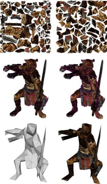
Re-atlasing. Many input textured meshes are generated using automated algorithms, which often create a complex texture atlas with fragmented and irregular texture seams. The extreme case occurs when all triangle edges correspond to
seams (Figure 4 (bottom)). In other cases, most texture map-ping methods are LOD-unaware and hence unfit to effective progressive compression.
Such fragmentation may generate high visual distortion, as the texture mapping is no longer representative of the input data after decimation. More specifically, during decima-tion the triangles having uv-coordinates in different texture patches are merged. The initial texture seams are thus not respected and the areas covered by the mesh triangles over the texture tend to shrink or expand as the decimation pro-ceeds (Figure 4 (top)). One solution is to preserve the seams as much as possible, but the quality of the coarse LODs inevitably drops as decimation proceeds.
This motivates a complete re-atlasing process as investi-gated in [18], in which we re-parameterize the input mesh onto the abstraction mesh, while reducing fragmentation and length of texture seams. The decimation is later driven to-ward the abstraction while being constrained to preserve the seams of the new atlas.
More specifically, we first cluster all triangles of the input mesh such that each cluster corresponds to one triangle of the abstraction. We then form a texture patch for each cluster by computing a planar parameterization onto the corresponding abstraction triangle. At this point, and depending on the complexity of the abstraction, the new texture atlas may still contain a large number of seams which constrain decimation and are costly to single-rate encode as each seam requires duplicated texture coordinates. We thus pack the triangular texture patches by gluing the triangles as much as possible, so as to trade low number of texture seams for limited texture
Figure 3: Abstraction. Left: input mesh (1.3M ver-tices) without texture. Right: abstraction generated by mesh decimation (300 vertices).
Figure 4: Artifacts due to texture seams. Top: Arti-facts during mesh decimation. Bottom: each edge of the input Taichi mesh is a seam (green).
distortion. All texture seams that are glued are first saved as “virtual seams” which are preserved during decimation.
After re-atlasing, both the abstraction and the input mesh are assigned new uv-coordinates onto the newly generated texture atlas.
3.3
Progressive Geometry
From the re-atlased input mesh we now generate the geom-etry stream of refinement via a “fine to coarse” reduction approach.
3.3.1 Initial Quantization. First and foremost, to gain in compression rates we perform a global, uniform quantization process for both vertex and texture coordinates by turning the continuous coordinates into integer ones, using respec-tively Qgand Qt bits. The initial values Qg and Qtare large
enough to yield a negligible distortion. Then, they are auto-matically readjusted by our framework to best fit our model, as discussed next.
3.3.2 LOD Generation. We then generate the LODs by per-forming a heterogeneous sequence of reduction steps. Because we position ourselves for being lossless in terms of mesh con-nectivity, we choose to use the conventional batched mesh decimation approach introduced in [8] with the edge collapse operator to achieve finer granularity. As adaptive quantiza-tion seemed to have a high potential reducing the bit-rate [12], we add extra steps of decrease in the quantization bits for mesh attributes. We illustrate the versatility of this generic framework by providing modular components to decimate the mesh via either half or full-edge collapse operators, re-duce the quantization bits for vertex coordinates or texture coordinates.
Figure 5: Re-atlasing. Top: input atlas and new at-las. Middle: input seams and seams after re-atlasing via the abstraction mesh. Bottom: abstraction and textured abstraction mesh.
Hence, the type of each step is simulated and we choose the best among the following types:
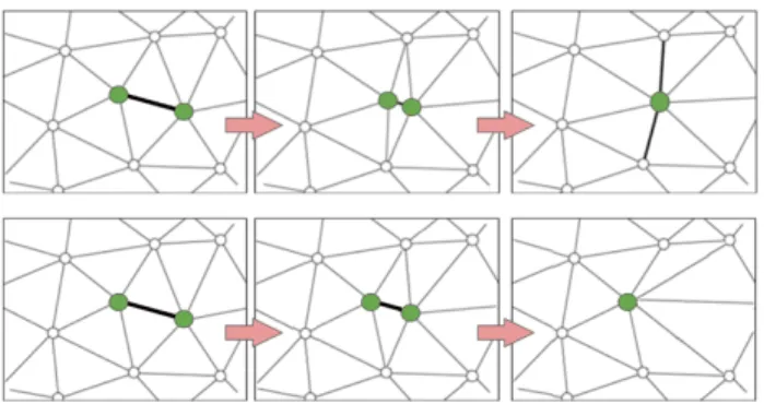
• Full-edge decimation step: We perform a batch of full-edge collapse operators, using the quadric error metric extended in 5D for textured meshes [9] to select which edge are going to be collapsed and compute the location of each merged vertex. Mesh decimation is driven toward the abstraction and it is constrained to preserve the discontinuities of the new atlas to ensure that the texture remains valid for all LODs.
• Half-edge decimation step: Similar to the full-edge decimation step, except that the merged vertex is re-stricted to be located to its two ancestors (see Figure 6). This step is less expensive in terms of bits but yields
Figure 6: Local mesh operators. Top: full-edge col-lapse operator. Bottom: half-edge colcol-lapse operator.
a larger distortion than its full-edge counterpart. Hence it is mostly used during the first reduction steps, as the distortion remains low.
• Quantization step for xyz vertex coordinates: Qg is decreased by one by relocating each vertex at a
3D cell center of the coarser quantization grid, where a coarser cell contains eight cells from the finer grid. It is an expensive step in terms of size and can cause a very high distortion if the grid is too coarse compared to the current state of the mesh. That is why it is chosen once a while only when the grid is way finer for the mesh. Most importantly, it helps reducing much the following decimation steps and the single-rate lowest LOD in size.
• Quantization step for uv texture coordinates : Qtis decreased by one by relocating each uv coordinate
at the 2D cell center of the coarser quantization grid, where a coarser cell contains four cells of the finer grid. Same comments as the previous step but applied for the parameterization grid.
More details about these steps are given below. Note that the first quantization reduction steps chosen before any other step are discarded and not added to the final bit-stream. They are used to readjust our initial quantization bits Qg
and Qt.
3.3.3 Multiplexing. Each of the several types of steps above: half-edge decimation, full-edge decimation, xyz quantization, uv quantization induces an increase of distortion ∆D, and
reversing a step during decoding requires a certain number of bits ∆R. In other words, we can trace backward (from right
to left) the (staircase) rate-distortion curve for the whole sequence of steps, up to the translation of the curve along the bit-rate axis. What remains to decide is the type of each step. To do so we compute different local agony equating to ∆D∗ ∆Rfor types of steps, and select the step with smallest
agony. Note that we depart from Lee et al. [12] who select instead the vector (−∆R; ∆D) forming the smallest slope.
The latter works well when the steps have similar bit-rates and different distortions but it fails when they have similar
distortions as the step with higher bit-rate would be selected. Instead, the local agony handles both cases.
The sequence of steps progresses until the user-specified maximum distortion error, already used for the above abstrac-tion, is met. The connectivity cannot be simplified beyond the one of the abstraction due to the seam-preserving con-straints. Finally, we single-rate encode the lowest LOD mesh with lowered quantization bits via the single-rate compression algorithm from the DRACO library, consuming 1.3 bpv on average. We detail next the mesh decimation process. 3.3.4 Mesh Decimation. The constraint to restore the input mesh connectivity for the highest LOD led us to apply the common batched decimation paradigm. Mesh decimation proceeds by batches of independent edge collapse operators sorted in a priority queue.
Independent set. We use during decoding a canonical order-ing of the vertices to locate the vertex split operators which reverse all the edge collapse operators, within the current batch. Such a canonical order differs form the order of the edge collapse operators applied during the decimation, which depends on a priority queue. For this reason the collapsed edges must form a so-called independent set, i.e. must be sufficiently separated from each other such that each edge can be collapsed without interfering with the other edges in the set. That is, an edge cannot be collapsed if one of the vertices of its patch is the result of a previous edge collapse.
Error metric. We leverage the quadric error metric ex-tended in 5D to account for xyz and uv coordinates [9]. This approach preserves both the input mesh geometry and the re-atlased texture coordinates, and handles texture seams as well. The metric computes for each edge the optimal xyz-uv attributes of the resulting vertex upon collapse which min-imizes the error defined by the metric. In each batch the collapse operators are organized into a priority queue, where priority refers to their error upon collapse. The next collapse operator popped out of the queue is the one with the lowest error. We stop the decimation for a given batch when the cur-rent collapse error is greater than a user-specified percentile (30% by default) of the errors computed for the initial set of
edges of the batch.
Collapse operators. The main degree of freedom is the type of collapse/split operator. We propose a hybrid approach that combines batches of half-edge and full-edge collapse operators. In the full-edge collapse operator the location of the merged vertex is determined by minimizing the local error using the metric. Such a generality comes at the cost of having to encode two residuals between the merged vertex and its two ancestors, to reverse the operator during decoding. In the half-edge collapse operator the merged vertex is restricted to be located at one of its two ancestors (see Figure 6). While the local error may be larger than that of the full-edge collapse operator, it requires to encode only one residual vector to reverse the operator during decoding. Intuitively, this operator proceeds by subsampling instead of resampling the mesh vertices. Note that the midpoint variant used by
Caillaud et al. [2] also requires a single residual, at the expense of a higher distortion.
Intuitively, the vast majority of the batches operating on a really dense mesh can rely upon half-edge collapse operators at lower bit-rate, while the ones operating on a very coarse mesh require using the full degrees of freedom with careful vertex optimization, and hence the full-edge collapse opera-tor. This approach departs from previous work by switching operators several times during decimation. If we use instead batches of only half-edge collapse operators our final bit-rate is reduced by 5% but we increase the agony by 2%, and if we use instead batches of only full-edge collapse operators our final bit-rate is increased by 27% and we increase the agony by 3%.
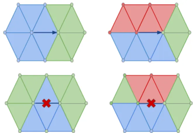
Decimation toward abstraction. Seam-preserving decima-tion avoids artifacts around the texture seams. In addidecima-tion, preserving the texture seams and the virtual seams of the re-atlas texture enables to drive the decimation toward the abstraction. Similar in spirit to Sander et al. [18], seam-preserving decimation is achieved by constraining the edge-based operators to match the following rules, that hold inde-pendently from the type of edge collapse operator selected for the current batch:
• If one of the edge vertices is on a seam, resp. corner, then only half-edge collapse toward the seam, resp. corner (Figure 7, bottom).
• Do not collapse the edge when its two vertices are on a seam but it is not a seam itself, or when the two edge vertices are on texture corners (Figure 7, top). 3.3.5 Encoding Inverse Mesh Decimation. The inverse mesh decimation process consists of batches of independent vertex split operators. Each batch requires both a combinatorial information (which vertices to split, and how to update the connectivity during vertex split) and a continuous information (where to relocate the two vertices after splitting, in xyz − uv space). We describe next several ideas to further decrease the compression rates.
Figure 7: Seam-preserving operators. Top: half-edge collapse. Bottom: do not collapse.
Vertex Split Location. After each decimation batch the mesh vertices are ordered in accordance to a canonical span-ning tree traversal, and the vertices to split are identified by a sequence of binary symbols. This sequence is shortened by omitting the vertices that cannot be split due to the constraints of having an independent set of split operators and costs 3.2 bpv [2]. For each split vertex we encode after prediction the geometry, connectivity and texture mapping data.
Connectivity. As geometry data consume more bits in gen-eral, we encode connectivity first in order to help predict geometry. When splitting a vertex into two vertices, recov-ering the connectivity information requires indicating how the two vertices are connected to their neighbors. As in most cases the surface remains locally 2-manifold, we encode in separate contexts the manifold and non-manifold cases. An edge collapse can transform a non-manifold connectivity into a manifold one, and vice-versa. We thus use a binary symbol to indicate a topological change. For the non-manifold connec-tivity cases we reuse the symbols proposed by Caillaud et al. [2] which handle arbitrary patches. For manifold connectivity cases, the umbrella of the split vertex is split into two parts. The first part is formed by the vertices that are connected to only one vertex of the (un-collapsed) edge, either the first or the second, which forms two sets. The second part if formed by the two vertices that delineate the boundary of these two sets, which are connected to both edge vertices, forming two new triangles. During decoding we need to identify these two boundary vertices and to assign to each set its connected vertex.
For encoding the boundary vertices of the umbrella, we utilize the notion of diameter of a point set, that is, the two boundary vertices of the umbrella that are furthest apart as a predictor for deriving the direction of the split edge. We then compute the bisector plane of the diameter, and order the umbrella vertices according to their probability to be the split vertex, which we assume to be related to the distance to the bisector plane of the two diameter vertices (Figure 8). More specifically, the two vertices that are closest to the bisector plane are predicted as split vertices. This predictor yields reduce the bit-rate by 7% compared to an arbitrary traversal to find split edges. Having the two boundary vertices, and thus the two sets of the patch vertices (left and right side from the boundary vertices), we use one bit symbol to record which set is connected to which vertex. Overall, we obtain 5.56 bpv versus 7.03 bpv for [2], which instead encodes first the geometry in order to predict the connectivity.
Geometry. Encoding the two vertex locations v1 and v2
after vertex split requires two residuals to reverse the full-edge collapse, and only one residual for the half-full-edge collapse. We leverage the already decoded connectivity, and perform two independent and sequential barycentric predictions for v1then v2, (in the full-edge collapse case) using the vertices
of their respective patch. Once v1 is decoded we utilize its
Figure 8: Diameter-based prediction. The diameter, connecting the two furthest vertices, is depicted in orange. The boundary vertices are ordered in accor-dance to the distance to the bisector (plane in 3D) of the diameter.
operators are edge collapses, for a total of 9.8 bpv (a half-edge operator consumes on average 12b). The remaining 15% of the operators are full-edge collapses, for a total of 3.2 bpv (a full-edge operator consumes on average 22b). We obtain in total 13 bpv for the geometry with adaptive quantization. To do a fair comparison for this predictor against the state-of-the-art [2], we use fixed bits for quantization and obtain still 15.65 bpv versus their 17.35 bpv.
Texture coordinates. The uv texture coordinates are pre-dicted similarly to the parallelogram prediction scheme used in DRACO, which utilizes the xyz and uv coordinates of the triangle vertices to predict new texture coordinates. The results are comparable to the one generate by the predictor used in recent work [2] (6.5 bpv using adaptive quantization). In case of texture seams, we encode extra indices to identify which face belong to which texture region as described in [2]. 3.3.6 Adaptive Quantization. Previously introduced in [12] for color meshes, adaptive quantization consists in decreasing the precision of vertex or texture coordinates as the mesh simplification progresses. Intuitively, the increase of distortion induced by coarser quantization is smaller for a coarse than for a dense mesh. A quantization step reduces by one the number of quantization bits for a coordinate type. This is performed when the grid is way finer for the mesh, via relocating all vertices of the current LOD, in either xyz or uv space to the centers of a coarser grid of integers.
Reversing this operation requires relocating each vertex to the center of smaller child cells (8 in xyz, resp. 4 in uv space), which consumes respectively 3 and 2 bpv. Predicting the new location is possible based on the distance to the centroid of the neighboring vertices of the parent cell, as proposed by Peng et al. [15] and used by Lee et al. [12]. However, and as the decimation deteriorates the mesh regularity, this predictor yields a negligible gain of 0.02 bpv.
Such an adaptive quantization step is costly, but its cost is compensated by the gain obtained on the geometry and texture mapping residuals in the next decimation steps. In addition, it helps improving the compression rate of the
lowest LOD as we can use single-rate compression with lower quantization bits, which shifts the rate-distortion curve to the left. Our multiplexer selects a low number quantization bits for the coarser LODs. By switching off the adaptive quantization, the agony is increased by 17%.
3.4
Geometry and Texture Multiplexing
We encode the texture via the standard progressive JPEG algorithm [16, 21] as it is widely known and integrated. We then multiplex the progressive geometry and texture data from coarse to fine, as we obtain better performance than proceeding fine to coarse as introduced in [2]. This is made possible by the fact that the texture and the geometry data are independent. Specifically, starting from the LOD0 which pairs the coarsest mesh and coarsest texture, we select to refine either the geometry or the texture based on the smallest agony, which is this time equivalent to the steepest slope.
Figure 9: Geometry and texture multiplexing. Each dot on the graph represents a pair (mesh and tex-ture), and multiplexing amounts to find the best path connecting the left-bottom and right-top dots.
3.5
Bitstream
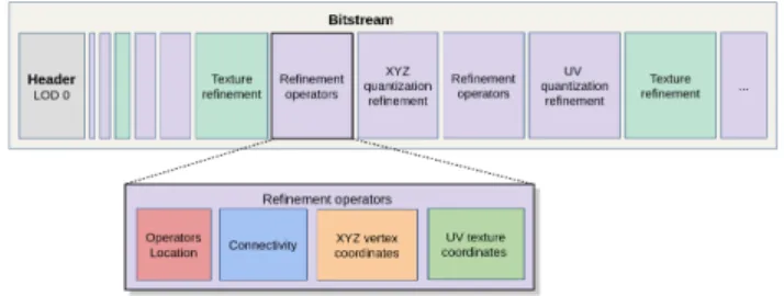
Figure 10 depicts the content of output binary bitstream after encoding. The header records the lowest LOD mesh encoded via DRACO, the lowest resolution texture encoded via progressive JPEG, the number of bits used for xyz and uv coordinates and the bounding box required to reverse the quantization process. The rest of the file records the heterogeneous series of geometry or texture refinements.
A geometry refinement can be either a batch of xyz quan-tization refinements, a batch of uv quanquan-tization refinements or a batch of mesh refinement operators. Each batch of re-finement operators is organized as follows:
• Vertex splits location. We entropy encode the bits required to recover the bit-mask of the independent
Figure 10: Output bitstream.
set of vertices to split, in a canonical order along a spanning tree.
• Connectivity. The connectivity symbols after diameter-based prediction are encoded using an entropy coder. • Geometry. We entropy encode the quantized residuals after barycentric predictions. For special half-edge col-lapse operators (such as half-edge colcol-lapse toward a seam), we record the orientation of the half-edge via extra binary symbols. The regular half-edge collapse operators do not require any extra bits as they are performed in a canonical orientation.
• Texture coordinates. We entropy encode the quantized residuals of uv coordinates.
• We entropy encode the indices of texture regions for collapse operators located near the seams, such that the uv coordinates are assigned to the right texture location.
These different symbols, organized into separate contexts, are encoded using the DRACO ANS entropy coder.
For example, the Tiger model bitstream contains 43 batches of mesh refinement operators, 2 xyz quantization refinements, 3 uv quantization refinements, 20 texture refinements and the header which represent respectively 58%, 4%, 3%, 32% and 3% of the total bitstream. Our average geometry compression ratio computed on all models shown by Figure 14 is 22x, meaning that our output bitstream is 22 times smaller than the input file.
4
SINGLE RATE ALTERNATIVES
Progressive compression is not the only way to provide the user with a refined depiction while the final high resolution mesh is loading. With a few more bits one can already send a first approximation and then, let the user wait for the rest or send even a few more single rate encoded LODs before sending the highest LOD. In these regard we discuss (1) a single-rate alternative to the progressive approach and identify (2) a promising hybrid alternative, that uses single rate encoding for the geometric part, while using the same progressively encoded texture image via a previous re-atlased step.
The alternative based on single-rate encoding first gener-ates a series of LODs, then selects the best subset in terms of agony and single-rate encodes them.
4.1
LOD Generation
While there are many ways possible to generate independent LODs, we propose the following LOD generation approach to carry an as rigorous as possible comparison with the progressive approach.
4.1.1 Geometry. The geometry is generated by decimating the re-atlased input mesh using QEM5D as error metric. Decimation is made “toward abstraction” while preserving the virtual seams of the re-atlased texture. Compared to the progressive approach we are not constrained by independent sets, and hence use a dynamic priority queue that produces LODs with higher quality. We generate LODs with the same mesh complexity than our progressive geometric LODs and compress them using DRACO, with the same number of quantization bits than the progressive LODs. This sequence of geometry LODs is referred to as SG.
4.1.2 Texture. We generate the texture LODs by downsam-pling with bicubic interpolation. The total number of LODs matches the ones of our progressive LODs, and the number of pixels of each LOD is determined by linear interpolation between the number of pixels of the input texture, and the total number of pixels that correspond to the same single-rate JPEG bit-rate than the lowest LOD of the JPEG progressive texture. This sequence of texture data is referred to as ST. 4.1.3 LODs. We now have the same number L of geometry LODs and texture LODs, in the order of 40 in our experiments. Instead of pairing the first geometry LOD from SG with the first texture LOD from ST and so on, we compute for all possible LODs (ie, L2 pair mesh/texture LOD) the pairs (bit-rate; distortion) and store them in an array. We then sort the L2 LODs by increasing order of distortion, and reduce the size of this array as follows. Let x and y be two different LODs, Dx (resp. Dy) be the distortion of x (resp. y) and
Rx(resp. Ry) be the bit-rate of x (resp. y). If Dx< Dyand
Rx< Ry, then y is discarded. The array is now also sorted by
decreasing order of bit-rate. This sequence of LODs is referred to as SGT. In these regards, qualities of single-rate LODs are better than the progressive LODs, since their geometry do not have to use the batched process via independent sets.
4.2
Best LOD Subset
Assume that we have N valid LODs, in the order of 125 for 40 initial geometry LODs. We must include both the highest LOD (to be lossless in terms of connectivity) and the lowest LOD (to avoid deciding about how to penalize the time until the first LOD is depicted). From these N − 2 intermediate LODs, it remains to determine which subset from these LODs yields the smallest agony. As trying all the 2N −2possibilities is too compute-intensive, we instead wish to find the best k intermediate LODs (k ∈ [0, N − 2]) which minimize the agony. Let A∗be the smallest agony overall and A∗x be the
Theorem: If A∗k< A
∗
k+1 then A ∗
k< A∗k+2and so on...
Thus A∗= A∗k
See proof in Appendix A. As we find that the optimal k is around 5, we can try out all combinations for small k, which obviously results in the best combination for that k. Define by OPT(LODs) the resulting optimal subset of this algorithm from a given set of LODs.
4.3
Naming LOD Sequences
In the sequel we name the following LOD sequences as follows: (1) OPT(SG): Optimal subset of single-rate geometry without texture costs (the full resolution texture is assumed to be already sent).
(2) PG: Progressive geometry without texture costs (full resolution texture already sent).
(3) OPT(SGT): Optimal subset of single-rate geometry sent with single-rate texture.
(4) OPT(SG) + PT: Optimal subset of single-rate ge-ometry multiplexed with progressive texture.
(5) PG + PT: Progressive geometry multiplexed with progressive texture.
All sequences above are generated with adaptive quantization. Progressive LODs (2),(5). They come from Section 3 and are straightforward as the progressive encoding leaves no choice as to which LOD is next.
Single-rate LODs (1),(3). We use the algorithm described in Section 4.2 to find the optimal LOD sequences from the LOD generated in Section 4.1 . OPT(SG) from SG with high resolution texture and OPT(SGT) from SGT.
Hybrid LODs (4). The hybrid approach OPT(SG)+PT comes from the geometry optimal LOD sequences multiplexed with a progressive texture. We use the previous re-atlas approach to generate a shared texture atlas for all LODs.
5
RESULTS
We implemented our progressive approach in C++, using the Draco library [4] for single-rate encoding of LOD0 and entropy/bit encoders, the progressive JPEG library for en-coding the texture, the Eigen library and OpenGL/OpenCV for the distortion measurement. Figure 14 depicts the set of models used to measure the rate-distortion performance. As the distortion due to the re-atlasing process is negligible (0.000711 for the Tiger model), all the following distortion scores are measured directly on re-atlased models. To get a meaningful interpretation of the following agony scores, note that sending only the high-resolution LOD using the single-rate state-of-the-art [4] yields an agony of 5.0 on the re-atlased Tiger, when ignoring the texture cost. This number corresponds to the agony value when the transmission is not progressive, i.e. when the user sees nothing on the screen until the full model is transmitted.
5.1
Comparison with Progressive
State-of-the-art
We compare our method with the recent state-of-the-art [2], see Figure 11. For fairness of comparison, we use our re-atlased mesh as input for both method. Next, we stop the state-of-the-art compression when reaching the same com-plexity and single-rate encode the lowest LOD, as performed in our approach. For clarity, and as we used the same progres-sive JPEG library (and associated compression parameters) we exclude the texture compression rates from the bit-rates.
Figure 11: Rate-distortion curves of the progressive state-of-the-art [2] and our method on the re-atlased Tiger. Our method (Green, agony: 0.133725) yields a better curve than the state-of-the-art (Red, agony: 0.196941).
Our progressive approach improves over the state-of-the-art in terms of agony, as recorded in Table 1. The lower agony in our method illustrates our superior LOD generation and compression strategies. It yields better quality in the transmission of textured meshes, meaning better LODs with fewer bits sent.
5.2
Comparison with our Single Rate
Alternatives
5.2.1 Without Texture Costs. We now compare OPT(SG) and PG, the performance of the progressive vs single rate alternatives without considering textures. That is, at all times, including LOD evaluation and selection, we used the full resolution texture and ignored the costs of transmitting it. For both approaches we use the reatlased texture. On the one hand, using the original texture would in general be a significant disadvantage for the single rate approach as this would be too restrictive, i.e., it would have to obey texture patch boundaries of the input while decimating. On the other hand, providing a new texture for each LOD would require taking the costs of textures into account, see next section. OPT(SG) and PG are utilized with adaptive quantization enabled for position and textures.
Figure 12: Rate-distortion curves for LOD sequences without texture costs on the re-atlased Tiger. PG (Green, agony: 0.133725) is a better curve than the
OPT(SG) (Red, agony: 0.159542).
The lower agony in the progressive case illustrates the smoothness and fine granularity of the approach, improving LOD quality with smaller bit chunks sent.
5.2.2 With Texture Costs. We now compare all approaches while including the cost for transmitting the texture, i.e. OPT(SGT), OPT(SG)+PT and PG+PT. For the pro-gressive approach (curve depicted in green) we now also use progressive texture compression which becomes an additional encoding/decoding step, i.e., all options of our framework we are now activated. For the single-rate we used the optimal OPT(SGT). We also investigated a hybrid approach that uses optimal single-rate geometry with progressive texture OPT(SG)+PT.
The progressive approaches with or without including the texture are better in terms of agony than the single-rate approaches, as recorded in Table 1. We acknowledge the fact that the hybrid OPT(SG)+PT is a valid alternative to the progressive. However, progressive compression has the advan-tage to be more adaptive to heterogeneous network latency and performance in terms of processing or rendering as each level takes advantage of the information already contained in the previous level. In addition, it generates smoother visual transitions between levels and most importantly requires to store and transmit only one file.
5.3
Timings
We ran our experiments on a laptop with an Intel core i7 clocked at 2.7GHz, with 32GBytes of memory. Most of the time is spent optimally packing the textures of the new atlas and using the screen-based error metric [6, 22] during geometry encoding and texture multiplexing. On an input model with 300k vertices and a 4.2M pixel texture, re-atlasing takes 84s, packing of the texture 1,838s, geometry encoding 926s and multiplexing with texture 158s. Decoding takes 0.03s to get the first level of detail, 3s before reaching a level of detail with a distortion close to 0, and 44s to recover
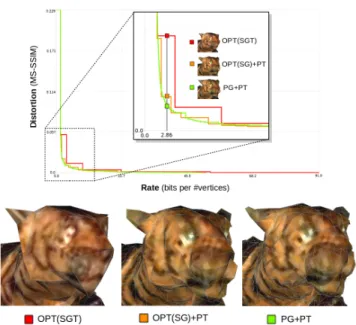
Figure 13: Top: Rate-distortion curves for LOD se-quences with texture costs on the re-atlased Tiger. Bottom: LODs at 2.86 bpv. PG+PT (Green, agony: 0.461431) is a better curve than OPT(SG)+PT (Orange, agony: 0.48670). OPT(SGT) (Red, agony:
0.632629) is the worst.
the input connectivity. Decoding is obviously not as fast as it should be. Specifically, we have been focusing on fast prototyping and therefore chose a very flexible (but slow) data structure.
6
CONCLUSION
Putting the user first, our ambition is to maximize the users experience with an application. By introducing the to be minimized “agony”, we are (to the best of our knowledge) the first to provide a well defined cost function that reflects this goal. The agony allows us to compare progressive trans-mission, even across different approaches, and to optimize progressive transmissions in the first place. Since the agony is also applicable to the degenerated case of sending just the single-rate encoded original mesh, we consider it as a generalization of the usual metric that quantifies the quality of a single-rate encoded model for a requested quality.
Following this narrative, our remaining contributions in-clude: (1) A generic framework for progressive mesh compres-sion that is driven by the above cost in the sense that in each round it simulates each possible encoding step and chooses the one that adds the least agony, aka, least area below that step; (2) A texture atlas generation scheme, essential step to any textured mesh progressive compression algorithm, that allows to share the texture among all LODs and enables mul-tiplexing of progressive texture image refinements; and (3) An optimal selection scheme for the subset among available LODs in case one is restricted to single-rate encoding.
Models # vertices without texture cost with texture cost
CVDL16 OPT(SG) PG OPT(SGT) OPT(SG)+PT PG+PT Aix 686,061 0.257466 0.298142 0.227286 0.541693 0.432085 0.358942 Ajaccio 617,257 0.265585 0.173482 0.166666 0.296426 0.288352 0.283547 Barabas 36,741 0.646291 0.654915 0.527746 6.831700 5.554740 5.178070 Bird 12,432 0.925169 0.624688 0.568855 2.827090 1.752870 1.723806 Dwarf 1,288,973 0.066505 0.062620 0.053197 0.299184 0.264752 0.259349 Maasai Man 99,564 0.565755 0.452293 0.441271 1.548940 1.276600 1.269712 Maasai Woman 112,513 0.479838 0.469566 0.422668 1.692860 1.305260 1.223950 Taichi 50,000 1.158152 0.706814 0.629271 3.933750 2.014700 1.929665 Tiger 314,218 0.196941 0.159542 0.133725 0.632629 0.486700 0.461431 Salamander 35,289 0.779823 0.643655 0.553208 4.670200 3.933090 3.795793
Table 1: For each model we record the agony of different approaches: CVDL16 is the progressive state-of-the-art [2], OPT(SG) (resp. OPT(SGT)) the single-rate alternative without (resp. with) the texture cost, OPT(SG)+PT the hybrid method, and PG (resp. PG+PT) our progressive framework without (resp. with) the texture cost. Our method yields a smaller agony than other progressive alternatives. Besides, progressiveness improves by a factor 20 the quality of the transmission versus sending the single-rate high-resolution only.
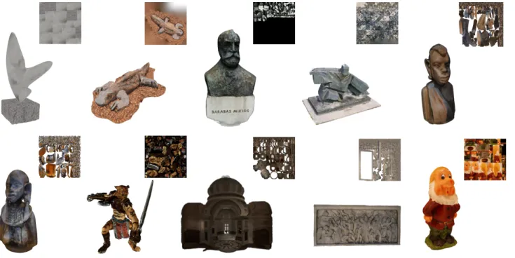
Figure 14: Gallery of input textured meshes used for measuring performances (number of vertices / mesh size in MB / texture size in MB). Top: Bird (12,432 / 1.5 / 0.66); Salamander (35,289 / 4.3 / 16.6); Barabas (36,319 / 6.9 / 3.9); Taichi (50,000 / 15.6 / 2.9); Maasai Man (99,564 / 19.2 / 2.1); Bottom: Maasai Woman (112,513 / 14.4 / 2.3); Tiger (314,218 / 60.1 / 2.9); Ajaccio (617,257 / 81.3 / 2.8); Aix (686,061 / 92.8 / 3.1);
We show that our progressive framework yields better results than the state-of-the-art progressive compression ap-proach [2] and single-rate variants. The re-atlasing together with the optimal selection scheme for single rate encoded LODs enables a hybrid approach that strikes a good compro-mise in case progressive geometry encoding is not available. Moreover, it enables a dual serving approach in which the server provides the LODs by the sequence of refinements steps, and in addition provides the single-rate encoded version of each LOD. This combines the advantages of both worlds. For instance, the client has full flexibility and can start the progressive transmission with any LOD of the sequence.
Limitations. Our approach requires that all LODs share the same topology and texture atlas. For models with com-plex topology a progressive approach with capability to refine the topology of the mesh and texture atlas during transmis-sion would be desirable. Then, starting with the geometry encoding and further multiplex the texture might not be the best solution, despite the fact that such a multiplexing is optimal in terms of agony. When we choose the next geom-etry refinement step, the distortion of each simulated step is measured using the high-resolution texture, which is not representative of the final bit-stream. Solving this issue would require adding the texture refinement step as an additional fine-to-coarse encoding step.
Future work. As future work, we wish to take advantage of the generic nature of our framework by exploring additional encoding steps. One of them consists in interchanging geom-etry and textures via so-called normal maps. We also plan to jointly generate and optimize the abstraction and re-atlas, so as to further optimize the later “agony”. We wish to explore more advanced predictors for the decimation or the adaptive quantization that depend on both the local mesh context and texture content. An approach with random access capability is highly desirable for large-scale scenes, but would deserve its own thread of work. Finally, as a natural extension of our work, we will deal with animated meshes and adapt our progressive compression framework for time-varying data.
ACKNOWLEDGMENTS
This work has been funded by Google, within the framework of the Chrome University Research Program. Pierre Alliez was also partially funded by the ANR, PISCO Grant number ANR-17-CE33-0005.
REFERENCES
[1] Pierre Alliez and Mathieu Desbrun. 2001. Progressive Compres-sion for Lossless TransmisCompres-sion of Triangle Meshes. In Proceedings of the 28th Annual Conference on Computer Graphics and In-teractive Techniques (SIGGRAPH ’01). 195–202.
[2] F. Caillaud, V. Vidal, F. Dupont, and G. Lavou´e. 2016. Progressive Compression of Arbitrary Textured Meshes. In Proceedings of the 24th Pacific Conference on Computer Graphics and Applications (PG ’16). Eurographics Association, Goslar Germany, Germany, 475–484. https://doi.org/10.1111/cgf.13044
[3] Michael Deering. 1995. Geometry Compression. In Proceedings of the Annual Conference on Computer Graphics and Interactive Techniques (SIGGRAPH). 13–20.
[4] DRACO 2018. Draco 3D Graphics Compression. https://google. github.io/draco/. Accessed: 2018-04-08.
[5] Michael Garland and Paul S. Heckbert. 1997. Surface Simplifi-cation Using Quadric Error Metrics. In Proceedings of the 24th Annual Conference on Computer Graphics and Interactive Tech-niques (SIGGRAPH ’97). ACM Press/Addison-Wesley Publish-ing Co., New York, NY, USA, 209–216. https://doi.org/10.1145/ 258734.258849
[6] Jinjiang Guo, Vincent Vidal, Irene Cheng, Anup Basu, Atilla Baskurt, and Guillaume Lavoue. 2016. Subjective and Objective Visual Quality Assessment of Textured 3D Meshes. ACM Trans. Appl. Percept. 14, 2, Article 11 (Oct. 2016), 20 pages. https: //doi.org/10.1145/2996296
[7] Jinjiang Guo, Vincent Vidal, Irene Cheng, Anup Basu, Atilla Baskurt, and Guillaume Lavoue. 2016. Subjective and Objective Visual Quality Assessment of Textured 3D Meshes. ACM Trans. Appl. Percept. 14, 2, Article 11 (Oct. 2016), 20 pages. https: //doi.org/10.1145/2996296
[8] Hugues Hoppe. 1996. Progressive Meshes. In Proceedings of the 23rd Annual Conference on Computer Graphics and Interactive Techniques (SIGGRAPH ’96). ACM, New York, NY, USA, 99– 108. https://doi.org/10.1145/237170.237216
[9] Hugues Hoppe. 1999. New Quadric Metric for Simplifying Meshes with Appearance Attributes. In Proceedings of the 10th IEEE Visualization 1999 Conference (VIS ’99) (VISUALIZATION ’99). IEEE Computer Society, Washington, DC, USA, –. [10] Guillaume Lavou´e, Laurent Chevalier, Florian Caillaud, and
Flo-rent Dupont. 2016. Progressive Streaming of Textured 3D Models in a Web Browser. In Proceedings of the 20th ACM SIGGRAPH Symposium on Interactive 3D Graphics and Games (I3D ’16). 203–203.
[11] Ho Lee, Guillaume Lavou´e, and Florent Dupont. 2012. Rate-distortion optimization for progressive compression of 3D mesh with color attributes. The Visual Computer 28, 2 (01 Feb 2012), 137–153. https://doi.org/10.1007/s00371-011-0602-y
[12] Ho Lee, Guillaume Lavou´e, and Florent Dupont. 2009. Adaptive Coarse-to-Fine Quantization for Optimizing Rate-distortion of Progressive Mesh Compression. Proceedings of Vision, Modeling, and Visualization, 73–82.
[13] Adrien Maglo, Guillaume Lavou´e, Florent Dupont, and C´eline Hudelot. 2015. 3D Mesh Compression: Survey, Comparisons, and Emerging Trends. ACM Comput. Surv. 47, 3, Article 44 (Feb. 2015), 41 pages. https://doi.org/10.1145/2693443
[14] Renato Pajarola and Jarek Rossignac. 2000. Compressed Progres-sive Meshes. IEEE Transactions on Visualization and Computer Graphics 6, 1 (Jan. 2000), 79–93.
[15] Jingliang Peng and C.-C. Jay Kuo. 2005. Geometry-guided pro-gressive lossless 3D mesh coding with octree (OT) decomposition. In SIGGRAPH ’05.
[16] PJPEG 2018. Libjpeg library. http://libjpeg.sourceforge.net/. Accessed: 2018-11-11.
[17] Jarek Rossignac. 1999. Edgebreaker: Connectivity Compression for Triangle Meshes. IEEE Transactions on Visualization and Computer Graphics 5, 1 (Jan. 1999), 47–61.
[18] Pedro V. Sander, John Snyder, Steven J. Gortler, and Hugues Hoppe. 2001. Texture Mapping Progressive Meshes. In Proceed-ings of the 28th Annual Conference on Computer Graphics and Interactive Techniques (SIGGRAPH ’01). ACM, 409–416. https://doi.org/10.1145/383259.383307
[19] D. Tian and G. AlRegib. 2008. BaTex3: Bit Allocation for Progres-sive Transmission of Textured 3-D Models. IEEE Transactions on Circuits and Systems for Video Technology 18, 1 (2008), 23–35.
[20] Costa Touma and Craig Gotsman. 1998. Triangle Mesh Com-pression. In Proceedings of the Graphics Interface Conference. 26–34.
[21] Gregory K. Wallace. 1991. The JPEG still picture compression standard. Commun. ACM (1991), 30–44.
[22] Z. Wang, E. P. Simoncelli, and A. C. Bovik. 2003. Multiscale structural similarity for image quality assessment. In The Thrity-Seventh Asilomar Conference on Signals, Systems Computers, 2003, Vol. 2.
[23] Sheng Yang, Chao-Hua Lee, and C.-C. Jay Kuo. 2004. Opti-mized Mesh and Texture Multiplexing for Progressive Textured Model Transmission. In Proceedings of the ACM International Conference on Multimedia (MULTIMEDIA). 676–683.
APPENDIX A: PROOF OF OPTIMAL
SINGLE-RATE LOD SELECTION
Assume that we have N LODs. As we exclude first and last one we have n = N − 2 intermediate LODs and we want to find the best k intermediate LODs (k ∈ [0, n]) which minimize the agony. Let A∗ be the smallest agony overall and A∗x be the smallest agony for k = x.
Let the “nothing on the screen” distortion be D0(= inf)
and the distortion of each LOD be D1, D2, ..., DN(= 0).
As-sumption: D0> D1> D2> ... > DN= 0. Let the individual
bit-rate of each LOD be R1, R2, ..., RN, Ribeing the number
of bits of LODiafter being single-rate encoding. Assumption:
0 < R1 < R2< ... < RN.
For a given k, let Dxi (resp. Rxi) be the distortion (resp.
individual bit-rate) of the ithselected LOD (i ∈ [1, k]), given that Dx1> Dx2> ... > Dxk and Rx1< Rx2< ... < Rxk. We
name xi∗the ith selected LOD of the subset which give the optimal agony A∗k. However for different k, each xi
∗
does not correspond to the same LODs (we do not pick necessarily the same LODs), that is why we will use yi∗or zi∗for different values of k. A∗0=D0× R1+ D1× RN ... A∗k=D0× Rx1∗+ Dx1∗× Rx2∗+ Dx2∗× Rx3∗+ ...+ Dxk−1∗× Rxk∗+ Dxk∗× RN A∗k+1=D0× Ry1∗+ Dy1∗× Ry2∗+ Dy2∗× Ry3∗+ ...+ Dyk−1∗× Ryk∗+ Dyk∗× Ryk+1∗+ Dyk+1∗× RN A∗k+2=D0× Rz1∗+ Dz1∗× Rz2∗+ Dz2∗× Rz3∗+ ...+
Dzk−1∗× Rzk∗+ Dzk∗× Rzk+1∗+ Dzk+1∗× Rzk+2∗+ Dzk+2∗× RN We now prove that if A∗k < A
∗ k+1 then A ∗ k < A ∗ k+2. Note
that: x1∗= y1∗ = z1∗ = 1, so we can remove D0× Rx1∗, D0× Ry1∗ and D0× Rz1∗of the equation because they have the same value. We start with A∗k< A
∗ k+1: A∗k< A ∗ k+1≡ Dx1∗× Rx2∗+ ... + Dxk−1∗× Rxk∗+ Dxk∗× RN< Dy1∗× Ry2∗+ ... + Dyk−1∗× Ryk∗+ Dyk∗× Ryk+1∗+ Dyk+1∗× RN A∗k < A ∗ k+1 implies that A ∗ k < Ak+1: if it is better than
optimal, it is better than any k + 1 LOD combination. Dx1∗× Rx2∗+ ... + Dxk−1∗× Rxk∗+ Dxk∗× RN< Dy1× Ry2+ ... + Dyk−1× Ryk+ Dyk× Ryk+1+
Dyk+1× RN
(1)
Substitute right part of (1) with the tail of A∗k+2
Dx1∗× Rx2∗+ ... + Dxk−1∗× Rxk∗+ Dxk∗× RN< Dz2∗× Rz3∗+ ... + Dzk−1∗× Rzk∗+ Dzk∗× Rzk+1∗+ Dzk+1∗× Rzk+2∗+ Dzk+2∗× RN
(2)
Adding Dz1∗× Rz2∗to the right part of (2) and we are done: Dx1∗× Rx2∗+ ... + Dxk−1∗× Rxk∗+ Dxk∗× RN < Dz1∗× Rz2∗+ Dz2∗× Rz3∗+ ... + Dzk−1∗× Rzk∗+ Dzk∗× Rzk+1∗+ Dzk+1∗× Rzk+2∗+ Dzk+2∗× RN ≡ A∗k< A ∗ k+2


![Figure 11: Rate-distortion curves of the progressive state-of-the-art [2] and our method on the re-atlased Tiger](https://thumb-eu.123doks.com/thumbv2/123doknet/13488386.413957/11.918.489.834.339.556/figure-rate-distortion-curves-progressive-method-atlased-tiger.webp)