HAL Id: inria-00587100
https://hal.inria.fr/inria-00587100
Submitted on 19 Apr 2011
HAL is a multi-disciplinary open access
archive for the deposit and dissemination of
sci-entific research documents, whether they are
pub-lished or not. The documents may come from
teaching and research institutions in France or
abroad, or from public or private research centers.
L’archive ouverte pluridisciplinaire HAL, est
destinée au dépôt et à la diffusion de documents
scientifiques de niveau recherche, publiés ou non,
émanant des établissements d’enseignement et de
recherche français ou étrangers, des laboratoires
publics ou privés.
On the Formal Execution of UML and DSL Models
Julien Deantoni, Frédéric Mallet, Charles André
To cite this version:
Julien Deantoni, Frédéric Mallet, Charles André. On the Formal Execution of UML and DSL
Mod-els. WIP of the 4th International School on Model-Driven Development for Distributed, Realtime,
Embedded Systems, Apr 2009, Aussois, France. �inria-00587100�
On the Formal Execution of UML and DSL Models
Julien DeAntoni, Frédéric Mallet, Charles André Aoste Team-Project
Université de Nice Sophia Antipolis INRIA Sophia Antipolis Méditerranée Email: [email protected]
Abstract
Model-Driven Engineering intensively uses models and model transformations. Transformation tools ensure that the target model conforms to the target metamodel, so that it is syntactically correct. However, there is few assistance, or none at all, to guarantee that the semantics is preserved during the transformation. This is mainly due to the absence of an explicit semantics within the models. Models bring the syntax while the related (application-specific) analysis tools bring their own semantics.
We propose here a model-driven approach to describe a formal and explicit semantics as a separate model. This formal semantics can then be attached to different UML /DSL models and a UML /DSL model can be executed with different semantics.
1. Introduction
To deal with complex systems, designers have always proceeded by building models that abstract away details to focus on the relevant aspects. In the domain of Distributed Real Time and Embedded Systems (DRES), adequate ab-stractions should allow early validation/verification of the system. Consequently, the model, and more important its underlying semantics, is often specific and driven by the expected kind of analysis.
For about thirty years, computer sciences have used various kind of models to abstract systems and perform analyses [1]. These models were first described by Domain Specific Language (DSL). DSL define entities that are sound in the targeted domain. Considering DRES and their need for analysis, these entities are then augmented with a formal semantics [2], [3], [4], [5], [6], [7]. One major problem of these approach is the multiplication of the languages. Moreover, for each proposed DSL, the associated tools must be developped. Two kinds of tools are particularly important: the (graphical) editors, which allow the model to be specified in a convenient way; and the analysis tools that manipulate the DSL. There are two main ways of analyzing models. First, a new analysis environment is developed for the specific use of this model. Second, a transformation is
realized from the model to the input language of an existing analysis tool.
The problems emerging from such an approach are twofold:
• It is difficult to benefit from all languages because their
semantics is described in various languages and the creation of bridges between these semantics require a fine knowledge about both semantics.
• Developing, for a given DSL, (graphical) editors,
anal-ysis tools or transformation models to other existing tools is a time-consuming activity.
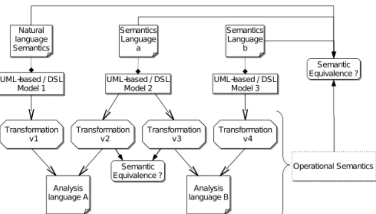
An (complementary) alternative to defining a DSL is to use the UML (Unified Modeling Language) [8], a general-purpose modeling language. UML is used in various do-mains and specifically well accepted in dodo-mains where structuration is a key issue for success while verifica-tion/validation is a second order concern. This is due to needs for general concepts that deliberately introduce varia-tion points in the semantics, itself described by using natural language. In DRES, analysis is a key issue, which explains the little use of UML. To enable verification/validation of UML models, a common approach is to use the profil-ing mechanism. A profile allows UML to be specialized, through stereotypes, with domain specific concerns. It is then possible to describe the semantics of the stereotypes and, based on this semantics, to make transformations to the input languages of existing analysis tools. Being a UML profile, it benefits from the large set of rapidly improving UML graphical editors. However, the semantics of the profile entities is either provided in a natural language from which transformations to analysis tool languages are derived, or scattered between the transformation and the semantics of the targeted language. In the first case, it is obvious that the semantics is only informal while in the second case it is hard to guarantee semantic equivalence between two transformations of the same model into different analysis languages.
The sum-up of these two main approaches is given in figure 1.
In this paper we are discussing the possibility to describe explicitly the semantics of a model as a separate model, which encapsulates a specific Model of Computation and Communication (MoCC) This MoCC may then be applied
UML−based / DSL Model 1 UML−based / DSL Model 2 UML−based / DSL Model 3 Analysis language A Analysis language B Transformation v1 Transformation v2 Transformation v4 Transformation v3 Natural language Semantics Semantics Language a Operational Semantics Semantic Equivalence ? Semantic Equivalence ? Semantics Language b
Figure 1. Current practice in using models for DRES
to one or more models. Consequently, on one hand it is possible to describe several semantics for a same model, and on the other hand, the formal semantics can be (tooled one for once(?)). Each developed tool or transformation models benefit from all models applying a MoCC described with our approach (?).
The second section of this paper clearly sum-up the ob-jectifs of the proposed approach and identify the underlying challenges. The third section describes the formal language used while the fourth and the fifth section shows how it is integrated in a model based approach. Finally, before to conclude, already developed tools are presented.
2. Objectives and challenges
To build semantic models and attach them to models and transformation models, we need to address five challenges described in this section. Each of the following sections proposes a solution for each of these five steps.
1) Provide a language general enough for the description of various MoCCs and ensure a formal operational semantics.
2) Describe the concepts of the formal language defined at step 1 in a metamodel whose instances are MoCCs. To do so, the proposed metamodel must allow a kind of genericity to represent the various possible MoCCs as libraries. Moreover, it must be possible to apply these MoCC libraries on several different kinds of models ranging from UML models to DSLs.
3) Augment the metamodel described in step 2 with the formal operational semantics dexcribed in step 1. This step makes the instances of this metamodel executable according to the formal semantics descrided in step 1. 4) Build tools that implement the previous steps in order to provide various outputs ranging from user feedback for models (exhaustive) simulation to specific analysis tools.
5) Select and apply an executable MoCC on a specific model to make it executable.
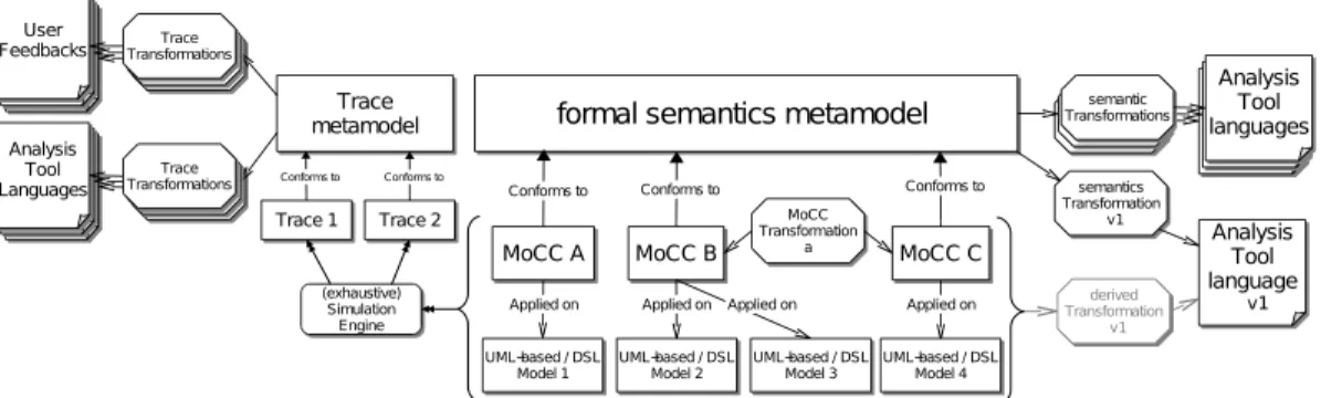
The global objectives resulting from these 5 steps are described in figure 2, which illustrates the different kinds of relations between the different models. Moreover, this figure also presents some desired tools like the simulation engine or the tools that realize the tranformations. The simulation can run models according to a specific MoCC and produce a trace model (that conforms to its metamodel). In the end of this section, we focus on transformations since various kinds of transformations are identified: MoCC transformations, semantic transformations and trace transformations. The MoCC transformations consider transformations between two MoCCs. To figure out the sense of these transformations, the reader can imaging two MoCCs A and B where A is a refinement1 of B. One can also imagine a semantically sound transformation between two very different MoCCs. The trace transformations manipulate the result of a specific simulation. This way it is possible to provide user feedbacks as well as bridges to analysis tools for specific analyses. The semantic transformations create a semantic bridge between the formal semantics of the very expressive formal language used in the approach and more specific analysis tool lan-guages, often dedicated to a specific kind of analysis. This way, a specific semantic transformation α, a UML-based or a DSL model and its explicit MoCC can be transformed, according to α, into an analysis tool specific representation to perform the analysis. This last transformation is named derived trasformation on figure 2.
By implementing each of these steps, we provide a MDK (Model Development Kit) where MoCCS relying on a formal semantics can be described and used for UML-based and DSL model simulations and analyses. Among the five presented steps, we believe that the three first ones are the most challenging and must be realized in a way that make the two last steps as simple as possible. We have developed a MDK named TimeSquare, which covers each of the previously presented steps. For each step, the rational and choices made in the implementation of this MDK are described in the next sections.
3. Formal language for MoCC description
The idea developed in this paper is to provide a lan-guage that allows the description of a specific operational semantics for the description of MoCCs, namely CCSL
(Clock Constraint Specification Language). The operational semantics of CCSL is given as SOS [9] and allows the associated abstract machine to execute models whose MoCC description is described in CCSL.
CCSL is a declarative language whose result is a CCSL
system. A CCSL system is composed of clocks and clock constraints imposed on the clocks. A clock constraint can be either a Relation or an Expression. One can notice that
MoCC A MoCC B MoCC C AnalysisTool language v1 MoCC Transformation a
formal semantics metamodel
Conforms to
Conforms to Conforms to semantics Transformation v1 Analysis Tool languages semantics Transformations UML−based / DSL Model 1 derived Transformation v1
Applied on Applied on Applied on Applied on UML−based / DSL Model 2 UML−based / DSL Model 3 UML−based / DSL Model 4 Trace metamodel Trace 1 Trace 2 Conforms to Conforms to Conforms to (exhaustive) Simulation Engine Trace Transformations User Feedbacks Trace Transformations Analysis Tool Languages Trace Transformations User Feedbacks Trace Transformations User Feedbacks Trace Transformations Analysis Tool Languages Trace Transformations Analysis Tool Languages Analysis Tool languages semantics Transformations Analysis Tool languages semantic Transformations
Figure 2. Proposed approach, centralized around a formal language for MoCC description
Clockis perhaps a misleading name since it is closer to an “activation conditions” rather that the physical device that measures time. However, this name comes from the strong connections between CCSL and the MARTE Time Model [10]. clock, CCSL systemand clock constraints are detailed in the next sub-sections.
3.1. Clock and
CCSLsystem
A Clock is an ordered set of instants (I), where ≺ is a quasi-order relation onI, named strict precedence.
A discrete-time clock c is a clock with a discrete set of instantsI. Since I is discrete, it can be indexed by natural numbers in a way that respects the ordering on I. c[k] denotes the kth
instant. Moreover, in the discrete case, each instant, but the first one, has a unique direct predecessor.
A set of clocks constrained by clock constraints defines a
CCSLsystem. More formally, aCCSLsystem is a pairhC, 4i where C is a set of clocks and where 4 is a binary relation onSc∈CIc, named precedence. 4 is reflexive and transitive.
From 4 we derive four new instant relations: Coincidence (≡ is defined by 4 ∩ <), Strict precedence (≺ is defined by 4\≡), Independence (k is defined by 4 ∪ <), and Exclusion (# is defined by ≺ ∪ ≻).
Instant relations are defined on pairs of instants. This is obviously not suitable for a time structure specification. Instead we have defined constraints on clocks: a clock constraint imposes many—usually infinitely many—instant constraints.
3.2. Clock constraints
A clock constraint can be either a clock relation or a clock expression. A clock relation refers two clock specifications that can be either a clock or a clock expression. It con-straints the partial ordering of clock instants of the clock specifications it refers to. A clock expression is a mean to construct a new clock from existing clock specification(s) and optionally additional parameters. A more detailed view of these two kinds of constraints follows.
3.2.1. Clock relations. Clock relations can be divided into three categories: synchronous, asynchronous, mixed.
Synchronous clock constraints rely on coincidence. Sub-sets is such a constraint: each instant of the subclock must coincide with one instant of the superclock. Of course, the mapping must be order-preserving.
Asynchronous clock constraints are based on precedence. Clock a strictly precedes clock b if for all natural number k, the kth instant of a precedes the kth instant of b (∀k ∈ N⋆, a[k] ≺ b[k]).
Mixed clock constraints combine both coincidence and precedence. For instance the sampling constraint: c = a sampledOn b constraints c to tick synchronously with b whenever a tick of a precedes a tick of b.
3.2.2. Clock expressions. A clock expression has an inter-nal clock that is coincident with the clock resulting from the expression evaluation whose semantics is given by SOS rules detailed in the next section.
There are three types of clock expressions: terminating, non-terminating and conditional. A terminating expression is a expression that has a clock whose set of instants (I) is finite. UpTo, which takes two clock specifications c1and
c2 as parameters, is such an expression: it produces a clock
coincident with c1until the next instant of c2. After the next
instant of c2, the resulting clock is said to be dead; i.e. the
clock will never tick again.
Conversely, a non-terminating expression has an a priori non-finite clock, i.e. a clock whose set of instants is infinite. However the death of a clock can be propagated so that noth-ing prevent a non-terminatnoth-ing expression from producnoth-ing a finite clock depending on the clock specifications used as parameter in the expression. union, which takes two clock specifications c1and c2as parameters, is such an expression:
it produces a clock whose an instant is add to I when an instant is add toI of c1 or to I of c2.
Finally, a conditional expression has a clock that is coin-cidenct with a clock specification c1 or a clock specification
c2depending on a boolean condition. c1and c2can be both
boolean expression specifies a coincidence with a dead clock specification.
The notion of dead clock is specifically important to build the the Concatenation expression. Concatenation takes two clock specifications c1and c2as parameters. c1concatenated
with c2 means that the owned clock is coincident with c1
as long as c1 is not dead. When c1 dies, the owned clock
is then coincident with c2. It is also important to notice that
this expression can be recursive.
3.2.3. Semantics of clock constraints. A CCSL system is a dynamic system and its behavior is defined by an infinite sequence of steps. A step consists of simultaneous clock ticks. When a (discrete) clock ticks, its current (local) index is incremented by 1. We call configuration of a time structure hC, 4i a mapping c : C → N. For each discrete clock clk, c(clk) is the current index of clock clk. This index denotes the current instant of clk.
For a set of clocks subject to a conjunction of clock constraints, the challenge is, “given a configuration, de-termine a step that meets all the constraints”. There may be 0 (inconsistent constraints), 1 (deterministic) or several satisfying steps (non deterministic).
To address this challenge, we have endowedCCSL with a Structural Operational Semantics. We defined SOS rules for a kernelCCSL (less than twenty rules) [11]. For illustration purpose, consider the “strictly precedes” relationship c1 ≺
c2. c1, c⊢ b1 c2, c⊢ b2 b ,(c(c1) = c(c2)) c1 ≺ c2, c⊢ b1∧ b2∧ (b ⇒ ¬c2) ( strictly precedes )
This rule reads that, for the given configuration c, con-straint “c1 strictly precedes c2” implies the Boolean
expres-sion on the right-hand side. In this rule, ck is a Boolean
variable associated with clock ck. ck = true means that
ck can tick. The Boolean expression refers to Boolean
ex-pressions (b1, b2) attached to the concerned clocks (c1, c2),
and imposes additional logical constraints, specific to the precedence relation:(b ⇒ ¬c2) or equivalently (¬b ∨ c2).
Clock constraints not defined in the kernel CCSL can be specified by composing primitive clock constraints.
A clock relation SOS rule is the same for all the CCSL system execution. However, expressions can be rewritten to change their internal state on given condition(s). Applying rewriting rulesfor all expressions yields a new set of clock constraints. For instance, considers the UpTo expression, which takes two clock specifications c1and c2as parameters
(noted ). The associated SOS rules for a given step is:
c1, c⊢ b1
c2, c⊢ b2
c0 = c1 c2, c⊢ b1∧ b2∧ ite(c2,¬c0,c0= c1)
( UpTo )
This specifies that if c2 ticks, the owned clock (named
c0 in the SOS rule) can not tick unless the owned clock c0
coincides with c1. A rewriting rule must be given to specify
that once c2 ticks, c0 must be dead at the end of the step.
This is the meaning of the following rule: c2∈ F
c0 = c1 c2−→c0 = 0
( UpTo rewrite )
In the UpTo rewrite SOS rule, we introduce 0that is a
special definition of a clock that never ticks. It specifies the semantics of a dead clock. Moreover, this SOS rule introduces t2∈ F , which means that c2 ticks at the current
step, a clear explanation of that follows.
From a CCSL specification we derive a set of Boolean expressions. Let B be the conjunction of all these ex-pressions. Starting with B, we determine the set of all possible (logical) solutions. From this set we deduce the set E of Enabled Clocks. A subset F (Fired Clocks) of E characterizes the new step. Not all subsets of E are correct solutions because a step must contain all or none of the clocks that have coincident instants. To derive F from E, the user chooses among different policies: minimal solution, maximal solution, random selection, and user’s defined policies. The default policy is the random policy that selects one out of all the correct solutions.
Beyond activation conditions and constraints on them, we have to refer to the different modeling elements of a system that can be of interest in order to be able to describe various MoCCs. This is one of the purpose of theCCSL metamodel presented in the next section.
4. MetaModeling
CCSLin an extendable way
To be fully integrated with UML-based and DSL models and to benefit from the MDE tools and facilities, it is important to be able to createCCSLmodel, which represents a CCSL system. CCSL provides a set of kernel constraints classified through expressions and relations. However, to be able to specify the possibly complex relations of a MoCC, it is important to be able to combined the kernel constraint to construct a library, which contains the MoCC relations. Finally, a new library may be built with relation(s) from one or more existing libraries; the metamodel must take this into account. This section overviews the proposed metamodel and the mechanism involved in the construction of libraries for MoCC.
Figure 3 shows a simplified metamodel of CCSL: aCCSL
system is a set of clocks and constraints. A constraint can be a Clock relation, which constraints together a right and
CCSL_System ClockConstraint KernelClockExpression ClockRef Natural ClockSpecification Clock ClockRelation constraints 0..* clock 1..1 left 1..1 right 1..1 clocks 0..* parameters 0..* operand 0..*
Figure 3. Simplified classicalCCSLmetamodel
a left clock specification. A Clock specification is either a clock expression or a simple reference to a clock. Finally, a clock expression can have parameters, simply represented by natural for short.
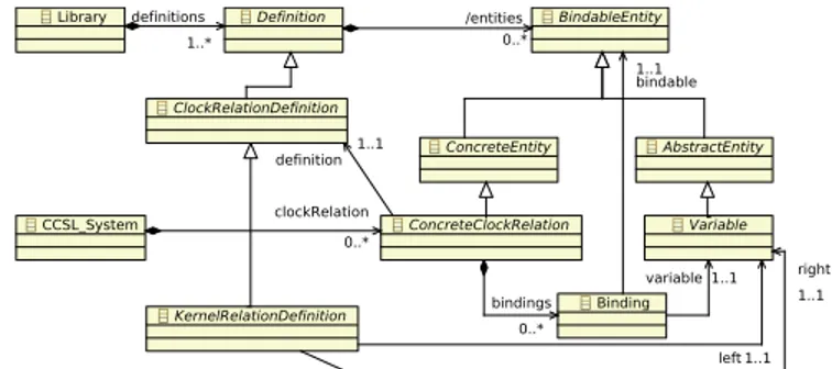
Using such a metamodel (of course more complex to be able to represent all the CCSL kernel) allows models to be defined. However, it is not possible to create reusable composition of clock constraints. What is expected is to define the equivalent of classical programming language functions, that can be defined and then called with the ap-propriate parameters when necessary. To do so, we propose a metamodel allowing the construction of library as the one presented in figure 4. This metamodel is a simplication of the one actually used. However, it is sufficient to understand the main principle. A library is a set of definition. A definition can be considered as a function definition in a classical programming language. A definition contains entities that can be either concrete or abstract. An abstract entity can be considered as a parameter in the prototype and in the definition of a function in a classical programming language. Following the same comparison, a concrete entity can be considered as an existing object in a classical object oriented programming language. A concrete relation is a concrete entity that is defined by a clock relation definition. It can be considered as a specific call to the function definition that is the clock relation definition. There are two possible uses of a concrete relation. It can be used in a definition to add some definition internal constraints or in aCCSLsystem to specify the application of a specific library on a Model to represent a MoCC. When used in a CCSL system, a concrete relation must bind with the variables of its definition some concrete elements in the same idea that a function call associates effective parameters to the formal parameters of the function definition. A binding is then used to link together a variable and a concrete entity. When a concrete relation is used in a definition, the bindings can either link the variables of their containing concrete relations to a concrete entity or to variables of the definition where it is used. For this reason, a binding links together a variable with either another variable
AbstractEntity ConcreteEntity BindableEntity ConcreteClockRelation Definition ClockRelationDefinition KernelRelationDefinition Variable Binding Library CCSL_System definition 1..1 /entities 0..* bindable 1..1 variable 1..1 bindings 0..* left 1..1 right 1..1 definitions 1..* clockRelation 0..*
Figure 4. Simplified extendableCCSLmetamodel
or a concrete entity depending on the case.
Finally, to be able to apply a specific CCSL system on a UML-based / DSL model, a clock owns an event that refers to an EObject, i.e. that can refer to every object of every eclipse based model. This way, applying a MoCC on a specific model consists in setting the reference between the event of a Clock and a UML-based / DSL model entity.
5. Augmenting the CCSL metamodel with the
CCSL semantics
In order to avoid loss of information, it was important to stay in the modeling world so that no “opaque” transforma-tions are necessary. To do so, we added the semantic directly at the metamodel level by using KerMeta [12]. KerMeta is a metamodelling language compliant with eMOF. One of the key features of KerMeta is a static composition operator, which allows extending an existing metamodel with new ele-ments (such as properties, operations, constraints or classes). This operator allows defining various aspects of a metamodel such as structure, constraints, semantics or transformations in separated units and integrating them automatically. The composition is done statically and the composed model is typed-checked to ensure the safe integration of all units. This mechanism allows the operational semantic to be specified without any modifications on the Ecore metamodel. We specified the operation semantic of CCSL in KerMeta and weaved the operations that specify how the CCSL concepts are executed according to the SoS rules previously presented. Moreover, because a binding mechanism was used, we used KerMeta to navigate through the model and to resolve, at run-time, the binding used by expresiosn and relations of user defined Libraries.
By implementing the SOS rules and rewriting rules as operations of the metamodel entities, we obtained a CCSL
metamodel, whose conforming models can be interpreted by the KerMeta framework.
6. Existing tooling and facilities
TIMESQUARE2 is the software environment we have developed to support the modeling approch presented in
section 2.
TIMESQUARE2 has four main features: 1) modeling of user defined libraries, 2) modeling of CCSL system and applying it to a specific model, 3) generation of a solution, 4) displaying and exploring waveforms, animating UML-based model and storing the result inside the model.
TIMESQUARE2 provides a basic environment for model specification (both libraries and CCSL systems) in eclipse. This environment also allows a simple way to apply a specificCCSLmodel on a specific UML-based / DSL model that are described in eclipse. Based on the KerMeta frame-work, it is possible to execute the CCSL system in order to simulate the UML-based / DSL models. A very crude version of the exhaustive simulation is also possible. The simulation of aCCSLsystem allows the generation of traces, given as waveforms written in VCD format. VCD (Value
Change Dump) [13] is an IEEE standard textual format for dumpfiles used by EDA (Electronic Design Automation) logic simulation tools.
Waveforms can be displayed with any VCD viewer. TIMESQUARE2 has its own viewer enriched with interactive constraint highlighting and access facilities.
For UML-based models graphically modeled with pa-pyrus2, it is also possible to animate the model. It is then possible to interactively navigate in the steps to see the state of the model entities for which CCSL specifications are applied on. Moreover, the state of model elements are store directly inside the UML model.
It is important to notice that TIMESQUARE2 uses a common trace model for all outputs. This trace model keep the trace between the model entities, theCCSLspecification and the resulting model element states. Moreover, it keeps additional information like the internal state of the CCSL
system, which can be usefull for better user feedback. Finally, the result of the (exhaustive) simulation can be injected in the CADP [14] model checker in order to be analysed.
7. Conclusion
In this paper we presented ongoing work for better manip-ulation of models with different operational semantics. To do so, we explicitly specify a formal operational semantics of a model as a separated model. It is then possible to explore the impact of different operational semantics on a same model. By providing a based language for MoCC description, it also provides facilities to take benefits of different tools developed for specific models. Amongst the several perspectives for this work, we can cite: providing better user feedback during model animation, facilitating the application of a MoCC on a specific model, providing an automatic selection of efficient analysis tool based on the MoCC description and the desired analysis, etc
2. http://www.papyrusuml.org
References
[1] F. DeRemer and H. Kron, “Programming-in-the large versus programming-in-the-small,” in Proceedings of the interna-tional conference on Reliable software. New York, NY, USA: ACM Press, 1975, pp. 114–121.
[2] S. Faucou, A.-M. Déplanche, and Y. Trinquet, “An ADL centric approach for the formal design of real time systems,” In Architecture description language, IFIP, pp. 67–82, 2004.
[3] project EAST-EEA, “Definition of language for automotive embedded electronic architecture,” Version 1.02, 2004.
[4] S. Vestal, “Metah user’s manual - version 1.27,” 1998.
[5] P.H.Feiler, B. Lewis, and S. Vestal, “the sae avionic architec-ture description language (aadl) standard: A basis for model-based architecture driven embedded systems engineering,” RTAS Workshop on Model-Driven Embedded Systems, 2003.
[6] R. Allen, “A formal approach to software architecture,” Ph.D. dissertation, Carnegie Mellon, School of Computer Science, January 1997, issued as CMU Technical Report CMU-CS-97-144.
[7] J. et al., “The cotre project : rigorous software development for real-time systems in avionics,” IFAC/IFIP/IEEE Workshop on Real-Time Programming, 2003.
[8] OMG-UML, “Final ftf report mof 2.0 core and uml 2.0 infrastructure finalization task force,” http://www.omg.org, 2004.
[9] G. D. Plotkin, “A structural approach to operational seman-tics,” 1981.
[10] The ProMARTE Consortium, UML Profile for MARTE, beta 2, Object Management Group, June 2008, OMG document number: ptc/08-06-08.
[11] C. André and F. Mallet, “Combining CCSL and Esterel to specify and verify time requirements,” INRIA, Research Report RR-6839, 2009. [Online]. Available: http://hal.inria. fr/inria-00360528/en/
[12] P. Muller, F. Fleurey, and J. Jezequel, “Weaving Executability into Object-Oriented Meta-languages,” Model Driven Engi-neering Languages and Systems: 8th International Confer-ence, MoDELS 2005, Montego Bay, Jamaica, October 2-7, 2005: Proceedings, 2005.
[13] IEEE Standards Association, IEEE Standard for Verilog Hardware Description Language, Design Automation Stan-dards Committee, 2005, IEEE Std 1364TM-2005.
[14] J. Fernandez, H. Garavel, A. Kerbrat, L. Mounier, R. Ma-teescu, and M. Sighireanu, “CADP-A Protocol Validation and Verification Toolbox,” Proceedings of the 8th International Conference on Computer Aided Verification, pp. 437–440, 1996.