HAL Id: hal-02529142
https://hal.sorbonne-universite.fr/hal-02529142
Submitted on 8 Jan 2021
HAL is a multi-disciplinary open access
archive for the deposit and dissemination of
sci-entific research documents, whether they are
pub-lished or not. The documents may come from
teaching and research institutions in France or
abroad, or from public or private research centers.
L’archive ouverte pluridisciplinaire HAL, est
destinée au dépôt et à la diffusion de documents
scientifiques de niveau recherche, publiés ou non,
émanant des établissements d’enseignement et de
recherche français ou étrangers, des laboratoires
publics ou privés.
Wong, Hervé Claustre, Thomas Trull, T. Udaya Bhaskar, Emmanuel Boss,
Giorgio Dall’olmo, et al.
To cite this version:
Henry Bittig, Tanya Maurer, Joshua Plant, Catherine Schmechtig, Annie Wong, et al.. A BGC-Argo
Guide: Planning, Deployment, Data Handling and Usage. Frontiers in Marine Science, Frontiers
Media, 2019, 6, �10.3389/fmars.2019.00502�. �hal-02529142�
doi: 10.3389/fmars.2019.00502
Edited by: Juliet Hermes, South African Environmental Observation Network (SAEON), South Africa Reviewed by: Shinya Kouketsu, Japan Agency for Marine-Earth Science and Technology, Japan Eric ’Pieter Achterberg, GEOMAR Helmholtz Center for Ocean Research Kiel, Germany *Correspondence: Henry C. Bittig [email protected]
Specialty section: This article was submitted to Ocean Observation, a section of the journal Frontiers in Marine Science Received: 15 March 2019 Accepted: 25 July 2019 Published: 22 August 2019 Citation: Bittig HC, Maurer TL, Plant JN, Schmechtig C, Wong APS, Claustre H, Trull TW, Udaya Bhaskar TVS, Boss E, Dall’Olmo G, Organelli E, Poteau A, Johnson KS, Hanstein C, Leymarie E, Le Reste S, Riser SC, Rupan AR, Taillandier V, Thierry V and Xing X (2019) A BGC-Argo Guide: Planning, Deployment, Data Handling and Usage. Front. Mar. Sci. 6:502. doi: 10.3389/fmars.2019.00502
A BGC-Argo Guide: Planning,
Deployment, Data Handling
and Usage
Henry C. Bittig1,2* , Tanya L. Maurer3, Joshua N. Plant3, Catherine Schmechtig4,
Annie P. S. Wong5, Hervé Claustre2, Thomas W. Trull6, T. V. S. Udaya Bhaskar7,
Emmanuel Boss8, Giorgio Dall’Olmo9, Emanuele Organelli2, Antoine Poteau2,
Kenneth S. Johnson3, Craig Hanstein6, Edouard Leymarie2, Serge Le Reste10,
Stephen C. Riser5, A. Rick Rupan5, Vincent Taillandier2, Virginie Thierry10and
Xiaogang Xing11
1Leibniz Institute for Baltic Sea Research Warnemünde (IOW), Rostock, Germany,2Laboratoire d’Océanographie
de Villefranche (LOV), CNRS, Sorbonne Université, Villefranche-sur-Mer, France,3Monterey Bay Aquarium Research
Institute, Moss Landing, CA, United States,4UMS 3455, OSU Ecce-Terra, CNRS, Sorbonne Université, Paris, France, 5School of Oceanography, University of Washington, Seattle, WA, United States,6CSIRO Oceans and Atmosphere, Hobart,
TAS, Australia,7Indian National Centre for Ocean Information Services (INCOIS), Ministry of Earth Science, Hyderabad,
India,8School of Marine Sciences, University of Maine, Orono, ME, United States,9Plymouth Marine Laboratory, National
Centre for Earth Observation, Plymouth, United Kingdom,10Laboratoire d’Océanographie Physique et Spatiale (LOPS),
Ifremer, CNRS, IRD, IUEM, University of Brest, Brest, France,11State Key Laboratory of Satellite Ocean Environment
Dynamics, Second Institute of Oceanography, Ministry of Natural Resources, Hangzhou, China
The Biogeochemical-Argo program (BGC-Argo) is a new profiling-float-based, ocean wide, and distributed ocean monitoring program which is tightly linked to, and has benefited significantly from, the Argo program. The community has recommended for BGC-Argo to measure six additional properties in addition to pressure, temperature and salinity measured by Argo, to include oxygen, pH, nitrate, downwelling light, chlorophyll fluorescence and the optical backscattering coefficient. The purpose of this addition is to enable the monitoring of ocean biogeochemistry and health, and in particular, monitor major processes such as ocean deoxygenation, acidification and warming and their effect on phytoplankton, the main source of energy of marine ecosystems. Here we describe the salient issues associated with the operation of the BGC-Argo network, with information useful for those interested in deploying floats and using the data they produce. The topics include float testing, deployment and increasingly, recovery. Aspects of data management, processing and quality control are covered as well as specific issues associated with each of the six BGC-Argo sensors. In particular, it is recommended that water samples be collected during float deployment to be used for validation of sensor output.
Keywords: ocean observation, ocean biogeochemical cycles, sensors, carbon cycle, ocean optics, best practices, argo
INTRODUCTION
The Biogeochemical-Argo program (BGC-Argo) was officially launched in 2016 with the goal to measure key biogeochemical ocean variables at a global scale. These observations support objectives within the three themes framed by the Global Ocean Observing System (GOOS): (i) climate change, (ii) marine ecosystem health and (iii) operational services. Within this context
BGC-Argo specifically addresses five science topics (ocean acidification, nitrogen cycling and oxygen minimum zones, biological carbon pump, ocean carbon uptake, and phytoplankton communities) and two ocean management topics (living marine resources and carbon budget verification), besides being a unique way to perform exploration of biogeochemical processes. To realize these objectives, BGC-Argo aims to organize and support the development and the sustained operation of a network of 1000 profiling floats. Each float will carry sensors to measure six core BGC-Argo variables: irradiance, suspended particles, chlorophyll-a (chl a), oxygen (O2), nitrate (NO3) and
pH (Biogeochemical-Argo Planning Group, 2016). In 2018, the measurement of these six variables was approved by the International Oceanographic Commission (IOC), paving the way for an internationally agreed upon monitoring of the global ocean in a way compliant with the Law of the Sea.
As of early 2019, the nascent BGC-Argo program has cost-effectively acquired more than 10,000 pH profiles, 30,000 nitrate and irradiance profiles, 60,000 chlorophyll-a and suspended particles profiles and 160,000 oxygen profiles, many of which were taken in regions of the global ocean that were observationally sparse in such measurements until now (Russell et al., 2014). This fast-growing network thus has the potential to rapidly fill observational gaps and subsequently revolutionize our understanding of global biogeochemical processes through support of enhanced data assimilation and modeling efforts, as well as through the ability to inform local process studies of varying scales. Accomplishing this development is a highly demanding task and the community that manages this network has to be prepared for this challenging and exciting future. The so-called “best practices” which follow are meant to ease the demands upon this community.
From the very beginning, the development of BGC Argo has been fortunate to follow in the footsteps and practices of the highly regarded core-Argo program (Riser et al., 2016). Argo was anchored on simple essential principles from the very beginning: data had to be freely available and distributed through a rigorous community-shared data management system. Upstream of data distribution, strong international coordination of deployments associated with high-quality reference measurement collection was mandatory. At the same time, evaluation and improvement of technology (sensors and platforms) was a constant preoccupation of the program and still is today. These principles are essential to the future of BGC-Argo, and an even broader commitment is under discussion to unite core-Argo, Deep-Argo (floats which can make measurements below the previous 2000 m Argo limit), and BGC-Argo efforts into a coordinated array, currently referred to as Argo2020 (Roemmich et al., 2019).
The goal of this “best practices” document is to develop the procedures required to provide the highest quality data to the largest possible end user community in a cost effective and timely manner. This is an ambitious task because such recommendations encompass the technological details associated with the preparation of profiling floats and their associated sensors, the ship based deployment operations at sea, the associated collection of at sea validation data, as well as the setup
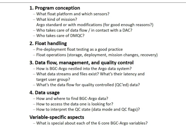
of the data stream and the quality control of the resulting data. The development of BGC-Argo should acknowledge and follow the example of the core Argo program and take advantage of lessons learned over the past 20 years. However, the enhancement of the float payload with BGC sensors adds complexity. In addition, some of the added sensors are in relatively early stages of maturity. Both aspects pose new challenges. The present paper is therefore timely, arriving at a time when the BGC-Argo program is emerging from its infancy, and when the details of its merger into Argo2020 are under active discussion (Roemmich et al., 2019). The community agreed best-practices outlined in the following sections are intended to give guidance to scientists new to the Argo community (see key questions in Figure 1) and will serve to promote continued growth and expansion of high-quality BGC-Argo data and inevitably help the program achieve long-term sustainability.
Up-to-date information on BGC-Argo such as participating countries and projects, BGC-Argo’s objectives, the network’s status, or links to the current data management documentation are available online at biogeochemical-argo.org.
1. PREPARATION AND DEPLOYMENT
CONCEPTION
Mission Considerations or the Global
Goal and the Compromises Required to
Achieve It
To be a part of Argo, a BGC-Argo float mission must conform to the guidelines set out by the Argo Steering Team1. A float
included in Argo:
• must follow the Argo governance rules for pre-deployment notification and timely data delivery of both real-time and delayed-mode quality controlled data,
• must have a clear plan for long term data stewardship through a national Argo Data Assembly Centre, and
• should target the core Argo profiling depth and cycle time, 2000 m and 10 days, respectively. However, data that contributes to the estimation of the state of the ocean on the scales of the core Argo Program are also desirable.
These guidelines also define three stages in the expansion of Argo: Experimental Deployments, Global Argo Pilot, Global Implementation. BGC-Argo has achieved the second stage for its recommended core set of six variables (oxygen, nitrate, pH, chlorophyll fluorescence, optical backscatter, and solar irradiance). Those variables were chosen based on availability of operational sensors and desired research and management needs. To achieve the next stage, the BGC-Argo implementation plan targeted a fleet of 1000 floats profiling on average every 6 days, i.e., fewer than 1 float per 300 × 300 km area of ocean (Biogeochemical-Argo Planning Group, 2016). This was primarily based on an observation system simulation experiment (OSSE) designed to quantify the minimum number
FIGURE 1 | Key points and questions of a “BGC-Argo float life”, from conception, float operations, data management and quality control to data usage.
of observational platforms needed to constrain global air-sea CO2 exchange (Biogeochemical-Argo Planning Group, 2016).
Additional methods, such as satellite ocean chlorophyll data denial experiments, where an increasing part of the data are withheld and the difference between subsampled and full resolution field investigated, as well as a general evaluation of decorrelation length scales for various ocean variables, were assessed and resulted in a similar recommendation for array size. To support and sustain such an array size, float endurance and longevity are a crucial factor. If float lifetimes are shortened because of rapid repeated profiling, more BGC-Argo floats have to be deployed to maintain the array. The BGC-Argo implementation plan aims for a 250 cycle/4 year lifetime with an average 6-day cycle interval (Biogeochemical-Argo Planning Group, 2016). This more rapid repeat cycle than the 10-day core-Argo mission does come with costs that are challenging for maintaining a global array (Roemmich et al., 2019). In addition, specific scientific goals, regional issues, funding sources, and even sensor configurations may motivate different missions, and we illustrate these issues with two examples below. Addressing these issues is challenging, and achieving the greater goal of a sustained global array will require compromises. As a starting point, we suggest that participants in BGC-Argo should, at a minimum, commit to achieving the 10-day repeat cycle for a targeted lifetime
of 4 years (i.e., 150 core BGC-Argo profiles over 4 years), profile down to 2000 m at least once a month, and target expending less than 20% of their float battery budgets addressing ancillary goals beyond the core BGC-Argo mission. Illustrative examples of the compromises required to meet specific science goals outlined in the BGC-Argo implementation plan include (i) the disparate optimal missions required for both the radiometer and chlorophyll sensors to contribute to the quantification of phytoplankton biomass and (ii) the measurement of net community production (NCP) using oxygen sensors.
Fluorescence observations as a measure of phytoplankton biomass are best done at night, because this signal is significantly compromised during the day by non-photochemical quenching (a response by phytoplankton to light that results in a reduction of fluorescence per unit chlorophyll, Kiefer, 1973). In contrast, assessment of biomass by the attenuation of the radiometer signal, and comparison of BGC-Argo sensor results to satellite remote sensing motivates measurements near noon. This combination merits obtaining both day and night profiles (IOCCG, 2011), and accordingly a mission with day-night pairs of rapid shallow profiles may be optimal. Interspersing these with deep profiles can meet core-Argo goals and also provide benefits for the bio-optical observations, because the increase in pressure significantly reduces the rate at which bio-fouling develops
(Gould and Turton, 2006) and deep “spikes” in bio-optical signals are indicators of particle aggregates important to export processes (Briggs et al., 2011). Importantly, many BGC-Argo floats may not initially deploy both fluorometers and radiometers, and thus this type of compromise may not be required for all floats. Note, however, that performing measurements at a given time of day or night will bias our ability to study the relationships between diel mixed-layer processes and observed parameters.
The oxygen sensor is useful to assess both changes in global ocean oxygen inventories and local biological activity, e.g., NCP as the balance between photosynthesis and respiration (Biogeochemical-Argo Planning Group, 2016, and references therein). These different goals have different optimal missions. Changes in whole of oxygen inventories are expected on decadal timescales (Stramma et al., 2010; Helm et al., 2011) motivating sustained array observations and requiring significant commitment to sensor stability assessments (Körtzinger et al., 2005;Bittig and Körtzinger, 2015;Johnson et al., 2015;Bushinsky et al., 2016). Options for assessing stability include:
• Periodic deep profiling into waters where oxygen concentrations can be considered stable and known (i.e., correction to climatology) – data at 2000 m appears appropriate for this along with assumptions about how biases from deep values should be used to correct values over the whole profile (for example assuming a constant gain or constant offset or their optimized combination, Takeshita et al., 2013; Bittig et al., 2018a). Deep profiles are required often enough to repeatedly sample waters of relatively constant temperature (T), salinity (S), and O2properties relative to the
shallower changes of interest, and thus the optimum frequency will depend on location.
• Use of a regional feature such as zero oxygen concentrations in oxygen minimum zones at mesopelagic depths as a special form of the climatological approach, without the requirement for as deep profiling (Wojtasiewicz et al., 2018b).
• Periodic measurement of atmospheric oxygen values using sensors that emerge from the sea, i.e., the optode on a stick approach (Bittig et al., 2015). In principle this is an improvement over deep climatological corrections, because the oxygen content of the atmosphere is spatially invariant relative to all ocean oxygen questions of interest and the sensor response is very sensitive at these levels, but is not achievable by all sensor types.
In contrast, NCP measurements, especially if they are to be scaled to satellite remote sensing of biomass to achieve global perspectives, require high temporal and spatial frequency observations, because NCP changes sign on diel cycles and control by zooplankton has shorter correlation length scales than the sub-mesoscale phytoplankton fields (e.g.,Abraham, 1998).
In summary, float deployments often serve multiple purposes and careful compromises must be made. This includes the optimal choice of sensors and the optimal choice of missions. Interspersing mission types or changing missions over the lifetime of the float can be a useful strategy to address these compromises. This can include reacting to events over the lifetime of a float, such as drifting into shallow waters that
preclude deep profiling or degrading responses from one or more sensors that motivate focusing on other goals than initially envisioned. All of these issues motivate committed ongoing involvement with float missions after deployment. Care must also be taken that these considerations do not become overly complicated but give full consideration to later data processing requirements, comparability to other floats and interpretability of data.
Data Management Considerations
Whether deploying a handful of floats or a larger array, giving adequate consideration to the structure of one’s data processing workflow in advance to float deployment is highly advised. Developing a working relationship with the local Argo Data Assembly Center (DAC) will serve to assist in this process, as each DAC acts as a gateway in the transfer of BGC data from float(s) to the Global Data Assembly Centers (GDACs). The float owner/principal investigator’s (PI’s) level of involvement/cooperation in float data processing and in the production of Argo-specific files can vary depending on availability of resources and personnel. However, certain issues, such as assigning a representative to manage delayed-mode quality control (DMQC) of core and BGC float data, will require some level of involvement on the float PI’s behalf. Additionally, it is worthwhile to anticipate the explicit needs of one’s user-base in the context of data management. For example, are there additional file formats or derived products (that fall outside of the Argo domain) that would be useful to one’s science team or external float-data users? If so, is there a potential avenue for production of such products within the operational data stream? Such questions are worthy of consideration as one plans a program and reaches out to one’s DAC representatives. Further details on such topics, including key recommendations with respect to data management and operations within the Argo system, are outlined in section “3. Data Management/Processing and QC.”
Platform Considerations
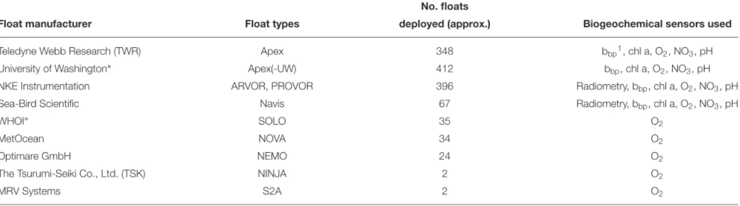
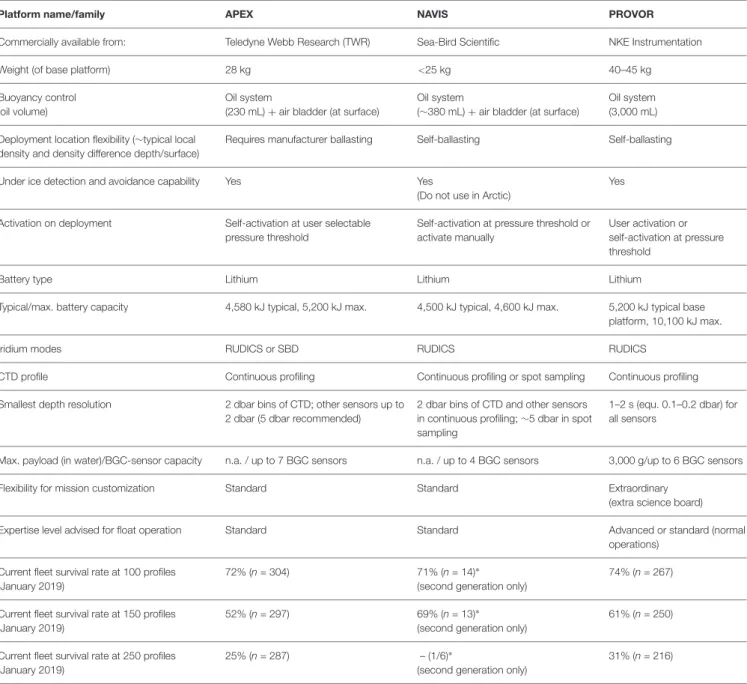
The specific float platform used is at the core of any BGC-Argo project. Different types of floats have different capabilities (e.g., number of sensors that can be accommodated, battery capacity, flexibility with respect to the frequency and vertical resolution of individual sensor measurements), which constrain how each sensor can be operated to achieve the required number of profiles. At present, there are nine manufacturers whose floats have been equipped with at least one BGC sensor (Table 1). The three most common commercially available ones are the Apex, Provor, and Navis floats, for which Table 2 gives a more detailed overview with respect to various float capabilities. Among these, Navis floats are the most lightweight and easy to handle, and Provor floats are the most flexible and adaptable thanks to two controller boards, a board for float operations and a science board for the sensors. Float energy budgets and telemetry systems should also be thoroughly understood prior to float selection and mission planning. As an example, an estimation of power consumption per profile is given in Table 3 for an Apex-UW SOCCOM BGC-Argo float (afterRiser et al., 2018) and an NKE PROVOR CTS4 remOcean BGC-Argo float. Additionally, Iridium rudics
TABLE 1 | Distribution of currently deployed BGC-Argo floats (as of January 2019) by float manufacturer/float type with list of biogeochemical sensors that have been used on these floats (not always concurrently). Information are compiled from AIC/JCOMMOPS and GDAC meta data.
No. floats
Float manufacturer Float types deployed (approx.) Biogeochemical sensors used
Teledyne Webb Research (TWR) Apex 348 bbp1, chl a, O2, NO3, pH
University of Washington∗ Apex(-UW) 412 b
bp, chl a, O2, NO3, pH
NKE Instrumentation ARVOR, PROVOR 396 Radiometry, bbp, chl a, O2, NO3, pH
Sea-Bird Scientific Navis 67 Radiometry, bbp, chl a, O2, NO3, pH
WHOI∗
SOLO 35 O2
MetOcean NOVA 34 O2
Optimare GmbH NEMO 24 O2
The Tsurumi-Seiki Co., Ltd. (TSK) NINJA 2 O2
MRV Systems S2A 2 O2
1Suspended particles via particulate optical backscattering b
bpmeasurements (Cetini ´c et al., 2012).∗Non-commercial.
communication is typically more cost-efficient for BGC-Argo than Iridium SBD communication (Riser et al., 2018). The choice of float, however, depends on multiple criteria and should be made separately for each project.
2. FIELD ASPECTS
Pre-deployment Testing
BGC-Argo floats are complex instruments that merit pre-deployment qualification. In general, pre-pre-deployment testing on the user side helps to increase confidence in float operation as well as to identify hardware and/or firmware flaws or glitches that may have catastrophic consequences if unnoticed. This may only affect a fraction of floats, but is important both on a fleet/network level and on an individual float level, given the investment of a BGC-Argo float.
Float manufacturers are expected to conduct similar tests prior to shipping floats to customers, to ensure proper functioning and best performance of their product. This is crucial to also enable contributions of small programs or individual researchers to the construction of the BGC-Argo network.
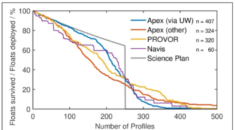
This section can only provide qualitative indications and few quantitative statements. The reason is that programs that deploy a certain kind of float in large numbers (i.e., with a sound statistical basis) tend to perform particular testing or adaptations to the floats since they have the necessary leverage, expertise and resources. For example, commercial TWR-built APEX floats and APEX floats built at the University of Washington (UW) have largely the same hardware. UW, however, intensively tests the hardware and float operations before deployment. In addition, UW also developed its own firmware that is different from TWR. Another example is the NKE Provor type of floats. The majority of floats (80% as of January 2019) pass through a pool test deployment (see below), allowing the identification and repair of malfunctions before deployment of both floats and sensors. The remaining ca. 20% of Provor floats pass through a test in an 8 m deep, water-filled basin at NKE, allowing verification of the float’s hydraulics. A comparison of float survival for these three sets of floats
as well as Sea-Bird Navis floats is given in Figure 2. UW’s thorough testing and adapted firmware dramatically improves survivability when compared to other APEX floats. The survival rate of Provor floats is in between UW’s and other APEX float’s and shows a higher fraction of floats with many profiles. Statistics for Navis floats are less robust due to fewer deployed floats (Figure 2). Note that they include floats both from the first generation (“NAVIS_A” model) and current generation (“NAVIS_EBR” model), which received a major redesign of the air/oil bladder system, as well as floats that underwent additional checking at UW.
As a general rule, appropriate time and resources should be allocated for testing and qualification prior to deployment. Everything that is feasible to test should be tested, which may also depend on the particular float type. Guidance can be obtained from manufacturers as well as details on the tests performed prior to float delivery. The depth of tests ranges from those carried out in port and on the ship, where the least amount of time and facilities are available, to tests carried out at a home institution with engineering facilities, where one has the most time and tools to check out the float. For this purpose, engineering facilities include technical personnel, an electronics shop, saltwater pool and pressure test facilities. It is considered good practice to perform pre-deployment tests, including whole platform operation “dock tests”/pool or at sea tests whenever firmware is changed significantly.
Part of (in lab) pre-deployment operations should include the completion and archival of all float-related metadata, including battery type and capacity, float and sensor types as well as serial numbers, and vertical offsets of BGC sensor positions relative to the pressure sensor, due to their attachment location (see
Supplementary Materialfor an example). Ideally, these metadata are supplied by the float manufacturer.
Example: University of Washington Float Qualification
In principle, there are three levels of float testing: (A) In lab (with engineering facilities and time prior to shipping), which include all tests of (B) and (C) (see Figure 3). (B) In lab (no engineering facilities, with time prior to shipping), which include all test
TABLE 2 | Qualitative comparison of common, commercially available BGC-Argo float types.
Platform name/family APEX NAVIS PROVOR
Commercially available from: Teledyne Webb Research (TWR) Sea-Bird Scientific NKE Instrumentation
Weight (of base platform) 28 kg <25 kg 40–45 kg
Buoyancy control (oil volume)
Oil system
(230 mL) + air bladder (at surface)
Oil system
(∼380 mL) + air bladder (at surface)
Oil system (3,000 mL)
Deployment location flexibility (∼typical local density and density difference depth/surface)
Requires manufacturer ballasting Self-ballasting Self-ballasting
Under ice detection and avoidance capability Yes Yes
(Do not use in Arctic)
Yes
Activation on deployment Self-activation at user selectable pressure threshold
Self-activation at pressure threshold or activate manually
User activation or self-activation at pressure threshold
Battery type Lithium Lithium Lithium
Typical/max. battery capacity 4,580 kJ typical, 5,200 kJ max. 4,500 kJ typical, 4,600 kJ max. 5,200 kJ typical base platform, 10,100 kJ max.
Iridium modes RUDICS or SBD RUDICS RUDICS
CTD profile Continuous profiling Continuous profiling or spot sampling Continuous profiling
Smallest depth resolution 2 dbar bins of CTD; other sensors up to 2 dbar (5 dbar recommended)
2 dbar bins of CTD and other sensors in continuous profiling; ∼5 dbar in spot sampling
1–2 s (equ. 0.1–0.2 dbar) for all sensors
Max. payload (in water)/BGC-sensor capacity n.a. / up to 7 BGC sensors n.a. / up to 4 BGC sensors 3,000 g/up to 6 BGC sensors
Flexibility for mission customization Standard Standard Extraordinary (extra science board)
Expertise level advised for float operation Standard Standard Advanced or standard (normal operations)
Current fleet survival rate at 100 profiles (January 2019)
72% (n = 304) 71% (n = 14)∗
(second generation only)
74% (n = 267)
Current fleet survival rate at 150 profiles (January 2019)
52% (n = 297) 69% (n = 13)∗
(second generation only)
61% (n = 250)
Current fleet survival rate at 250 profiles (January 2019)
25% (n = 287) – (1/6)∗
(second generation only)
31% (n = 216)
∗Relatively few second generation Navis floats (NAVIS_EBR model) are in the BGC-Argo array. Use the survival rate with caution.
of (C). (C) In port or on research vessel (no engineering facilities, limited time before deployment).
The tests of level A, in essence, control all movable parts of a float. For “dock testing” (level B), the float is put outside where satellite communication and GPS acquisition is possible. It then starts a “normal” mission, including buoyancy engine actions, satellite communications, and the sensors are sampled at least once as the float crosses one pressure table sample over multiple days of testing. It is set to cycle rapidly (e.g., 2 profiles per day) to verify normal float functioning. The in-port tests of level C are simple but nonetheless crucial to catch any issues which occur during shipping and should be standard practice for all deployments. Due to the large
number of sensors on these floats, they are very susceptible to damage in transit.
Example: Ifremer Pool Float Tests
Once sensors are individually tested and then mounted on the float, PROVOR BGC Argo floats undergo a pool test in the Ifremer pool (20 m depth, 50 m length). Each float slides along a line which is stretched between the bottom and the surface. The distance between the vertical lines is less than 1 m (Supplementary Figure S1). The pool is supplied by sea water, which is filtered and treated by additional bleach injection. The floats are launched like they are in an at-sea mission. They perform several cycles (typically 3). Parameters are measured at
T ABLE 3 | Energy budget estimate on a per pr ofile basis for UW-built SOCCOM APEX floats (left set; after Riser et al. , 2018 ) and for remOcean NKE PROVOR CTS4 floats (right set; 2000 m pr ofile). Total battery capacity for both floats is 5,200 and 8,600 kJ, respectively , which gives energy for nominally 262 pr ofiles for SOCCOM APEX floats and for 327 pr ofiles for remOcean PROVOR CTS4 floats. UW-Built SOCCOM APEX floats remOcean NKE PROVOR CTS4 floats System No. samples/ Energy J/ Energy kJ/ Per cent Per cent of System No. samples/ Energy J/ Energy kJ/ Per cent Per cent of pr ofile sample pr ofile of total core -only ∗ pr ofile sample pr ofile of total core -only ∗ Buoyancy pump 6. 42 32 .4 43 .8 Buoyancy pump 10 .25 39 .0 45 .5 ISUS/NO3 65 55 .7 3. 62 18 .3 24 .7 SUNA/NO3 90 8. 9 0. 80 3. 0 3. 6 SeaBir d 41CP 550 5. 5 3. 04 15 .3 20 .8 SeaBir d 41CP 890 5. 1 4. 56 17 .4 20 .3 Iridium-GPS 2. 50 12 .6 17 .1 Iridium-GPS 1. 13 4. 3 5. 0 electr onics (APF9i) 1. 99 10 .0 13 .6 electr onics 5. 42 20 .6 24 .1 Radiometry Radiometry 250 0. 9 0. 22 0. 8 1. 0 Durafet pH 65 19 .7 1. 28 6. 5 8. 7 Durafet pH FLBB 65 2. 5 0. 16 0. 8 1. 1 FLBBCD 660 3. 2 2. 13 8. 1 9. 5 Optode/O2 65 1. 5 0. 10 0. 5 0. 7 Optode/O2 415 1. 5 0. 62 2. 4 2. 8 Self-discharge 0. 70 3. 5 4. 8 Self-discharge 1. 15 4. 4 5. 1 TOT AL APEX 19 .81 100 .0 135 .2 TOT AL PROVOR 26 .28 100 .0 116 .7 ∗Shaded/italic numbers correspond to core-Argo systems and sum to 100 % total in this column.
FIGURE 2 | Float survival rate of Apex-UW (blue, n = 407) vs. other Apex floats (red, n = 324). Same for Provor floats (all types) (yellow, n = 320). Note that not all of the Provor profiles go down to 2000 dbar. Navis floats (both NAVIS_A and NAVIS_EBR models) are shown for completeness (purple, n = 60). About one third of the Navis floats underwent additional checking at UW. The gray line gives the float survival estimate from the BGC-Argo Science and Implementation Plan (250 cycle lifetime, average 6 days cycle interval, 90% survival rate per year;Biogeochemical-Argo Planning Group, 2016).
first descent, at the park depth (20 m), and during the ascent. These tests are a crucial way to identify and avoid bugs in new firmware pre-deployment.
Additionally, tests at sea can be made, e.g., off the bay of Villefranche-sur-Mer given easy access to deep water. The float is attached to a line with a buoy at the surface, and can profile from 0 to 200 m (see Table 4 for a pros and cons of such tests).
Float Storage
During storage or transport, freezing temperatures should be avoided. If the float is expected to encounter freezing temperatures, the conductivity-temperature-depth sensor (CTD) and pumped flow paths must be dried before shipment to avoid cracking of the conductivity cell. This holds true during shipping, home institution storage, or storage while on the deck of the ship before deployment. When preparing the float for deployment in such conditions, the float must be inside the ship and the deployment phase should be as short as possible (e.g., less than half an hour). Using insulated protection around the float and the sensors can be a way to limit thermal effects. Extreme temperatures (both high and low) can have an impact on the float calibration due to the acceleration of the deterioration of the filter of the radiometer, for example. The loss of energy from the main battery during storage is temperature dependent, with a typical self-discharge rate of 3% per year (Riser et al., 2018). Higher temperatures lead to an increase in self-discharge. This behavior is not specific to BGC floats.
Float Notification and Argo Governance
Since 2000, the implementation of the Argo program has been guided by IOC/UNESCO Member States and a set of resolutions (XX-6 and EC-XLI.4) and guidelines to meet coastal states legitimate transparency demand in the United Nations Convention on the Law of the Sea (UNCLOS) context. Resolution XX-6 (IOC, 1999) requested Argo implementers
FIGURE 3 | Pre-deployment float testing levels with steps undertaken based on University of Washington experience. Whether all three levels of float testing (A–C) can be performed depends on facilities and time available prior to deployment.
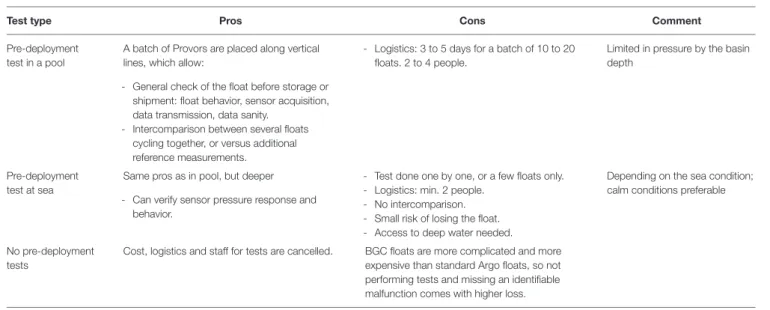
TABLE 4 | Comparison of float test deployment options with pros and cons based on Ifremer experience.
Test type Pros Cons Comment
Pre-deployment test in a pool
A batch of Provors are placed along vertical lines, which allow:
- General check of the float before storage or shipment: float behavior, sensor acquisition, data transmission, data sanity.
- Intercomparison between several floats cycling together, or versus additional reference measurements.
- Logistics: 3 to 5 days for a batch of 10 to 20 floats. 2 to 4 people.
Limited in pressure by the basin depth
Pre-deployment test at sea
Same pros as in pool, but deeper - Can verify sensor pressure response and
behavior.
- Test done one by one, or a few floats only. - Logistics: min. 2 people.
- No intercomparison. - Small risk of losing the float. - Access to deep water needed.
Depending on the sea condition; calm conditions preferable
No pre-deployment tests
Cost, logistics and staff for tests are cancelled. BGC floats are more complicated and more expensive than standard Argo floats, so not performing tests and missing an identifiable malfunction comes with higher loss.
to notify, reasonably in advance and through appropriate channels, any Argo float deployment in the high seas that might drift into Member States exclusive economic zones (EEZ). Resolution EC-XLI.4 (IOC, 2008) offered then the possibility to coastal states, through official request to IOC/UNESCO, to be formally and bilaterally notified of float drift into EEZ by implementers. This resolution and resulting guidelines clarified as well the right for the coastal state to request to stop data transmission in its EEZ. These rules apply to official Argo floats, endorsed by the Argo Steering Team, and not to any profiling float.
The Member States of the Intergovernmental Oceanographic Commission of UNESCO have agreed with Decision EC-LI/4.8 (IOC, 2018) to have BGC-Argo floats and their 6 core variables covered by the same notification regime as core Argo floats. This requires as well free and unrestricted data sharing in real-time; a mandatory rule for all Argo floats.
Practically, all BGC floats deployed in high seas, which might drift into Member States EEZs, will not require a clearance according to UNCLOS, but rather a bilateral notification from the implementer to the coastal state. Such notification is triggered by a real-time warning system set up at JCOMMOPS and its
Argo Information Centre (AIC)2, which assist implementers to
do so and concerns for now a dozen of coastal states. However, all Argo implementers have to seek a Marine Scientific Research (MSR) clearance (according to UNCLOS) for deployment of floats directly into EEZs for most of the Coastal States.
Any BGC-Argo float deployment needs thus to be notified with the AIC in advance of deployment. The AIC developed a centralized electronic notification system, which informs Member States of the float deployments. Float operators register their deployment (including early plans) in the AIC system, which will trigger a notification email including float deployment details, sensors equipped, configuration, contact points, etc. The availability of data is also checked by the AIC. In this process, each Argo float deployment will be assigned a unique identifier, its WMO number, which is also used in the data system.
Biogeochemical float deployments outside of Argo (and outside the Argo data system) are possible and fall under the rules of UNCLOS. This means that MSR clearances will have to be requested to coastal states in advance (i) for deployments into any EEZ and (ii) for drift into any EEZ.
Float Deployment
Float manufacturers follow different deployment philosophies. • Provor: Provor floats need to be shipped with their batteries
in switch-off state because of transport regulations, which requires an operator to switch them on prior to deployment. NKE floats are adjusted to maximum buoyancy before deployment (i.e., the float is shipped with its external oil ballast full) to prevent the accidental sinking and loss of an inactivated float. To be able to sink, these floats must reduce their volume (buoyancy) by opening a solenoid valve to bring the oil back into the hull. Activation is typically done just before deployment. The float then starts a sequence of self-tests which last a few minutes with success indicated by an audible signal, signaling that the float starts its volume reduction. This volume reduction and signal lasts 30 min and the user should not deploy the float after the signal has stopped to avoid too rapid sinking of the float. After deployment, it can take 30–40 min before the float leaves the surface, possibly longer in cold waters due to increased oil viscosity.
Alternatively, recent Provor floats can be activated in advance with a pressure threshold triggering the start of the mission (compare Apex/Navis behavior below), though this procedure is not recommended by NKE.
• Apex/Navis: Navis floats are shipped in a “frozen” mode and need to be connected to a computer using the serial (20 mA) connector to wake up (the magnetic interrupt switch cannot be used to wake up Navis floats). For APEX and Navis floats, startup can be done well in advance of actual deployment (e.g., in port). The float then reads its pressure sensor every 2 h. As the float is ballasted low, it sinks (passively) on its own, and typically leaves the surface after the cowling fills with water (2– 20 min). When the float’s pressure reading exceeds a 20 dbar threshold, the float starts its mission (“pressure activation”).
2http://argo.jcommops.org
Pre-deployment sensor-specific procedures should include the cleaning of optical windows (e.g., Talley et al., 2017). Upon deployment, metadata should be completed with location, time, concurrent observations, etc. (see Supplementary Material for an example).
Concurrent reference samples (e.g., calibrated CTD-O2cast;
bottle NO3, pH, chl a, HPLC pigments, POC samples; sensor
chlorophyll a fluorescence, bbp, radiometry profile) are taken
by many groups. This is good practice and recommended for validation, but not essential for calibration in most cases, see section “Variable-specific Aspects”.
Mission Modifications
Experience from some float groups suggests that daily profiles for the first 5 days after deployment as well as enabling descending and ascending profile acquisition (only possible on NKE floats) allow certain sensors (e.g., pH, O2) to stabilize faster for better
calibration against ship data. After these 5 days, the float can be configured to a standard Argo mode. This includes profiling to 2000 m depth at least once per month to allow appropriate salinity data qualification for the core Argo mission3.
Thanks to two-way communication, mission changes like those above are possible during deployment. This is a very useful capability, but should be used cautiously, depending on the detail of modification. If the level of the modifications is low and affects only standard parameters (e.g., float profiling or parking depth, cycle period), they can be easily changed. For example, the remOcean project floats in subpolar/austral areas follow a spring/summer bloom period-intensified schedule (i.e., cycle interval of 2 days in December–February, 5 days in March/April, 10 days in May–August, 5 days in September, and 3 days in November, respectively). More advanced modifications, that may not be available on all float types, include individual sensor on/off depths or sampling frequencies (e.g., possible on NKE, Apf11 floats). Other parameters can be very advanced and should be left to expert users.
In any case, any modification of parameters must be carefully checked in order to detect any conflict between them. Pre-validated missions should be used or, if available, a simulation software that assists the float operator in this task. The new mission parameters are directly connected with the firmware version of the float, i.e., the float version must be kept in the meta data. This information is crucial. The capability to change the float mission can become quite time consuming because the data subsequently transmitted by the float needs to be monitored frequently.
Float Recovery
This is only possible with two-way communication which permits a change in mission parameters to set a float into recovery mode. This mode keeps the float at the surface sending regular position updates at a higher frequency. BGC-Argo float recovery is becoming a common practice when logistics permit, e.g., in the Mediterranean or Baltic Sea, and allow post-deployment verification and recalibrations of sensors.
In the Baltic Sea, a permanent presence in the Gotland basin has been maintained by Argo Finland since 2013 using 2 floats interchangeably (Siiriä et al., 2018). The NAOS Mediterranean array has been maintained since 2012 with about a dozen active BGC-Argo floats and a total fleet of 30 BGC-Argo floats. Every 2–3 years, a ship cruise is dedicated to the recovery of old floats and the deployment of refurbished platforms (Taillandier et al., 2018; D’Ortenzio et al., in preparation). Recovered floats have been refurbished in the following way, serving as a template for others: Visual check of the sensors before cleaning, systematic replacement of batteries and o-rings in the lab, pre-deployment tests for ballasting, communication, mission configuration and software performance. In addition, sensors should be recalibrated as a best practice recommendation. Calibration/validation was performed during (re-)deployment using water samples of a concomitant CTD and bottle sample cast.
Recovering and redeploying floats is cost effective, eco-friendly, allows for sensor recalibration, and helps to maintain the BGC-Argo array and attain the BGC-Argo science goals (Biogeochemical-Argo Planning Group, 2016). It is thus recommended to check for recovery opportunities wherever possible. Note, however, that while float recovery and redeployment has many benefits, its feasibility is highly dependent on float location and related field logistics and is not mandatory within the Argo system. Only 4% of the current BGC-Argo array has been successfully recovered (as of January 2019), the majority of which were deployed in semi-enclosed seas.
The NAOS redeployment experience suggests that though the recovered battery voltages would allow a prolonged deployment, the bio-optical sensors were covered by a biofilm in most cases (depending onin situ conditions encountered), which decreased the data quality and became the factor limiting the mission. In contrast, optics and electronics of the bio-optical sensors were not critically affected even with high sampling rates. Overall, the choice to limit the deployment of the platform to 2–3 years (about 200 cycles) provided a better data quality and reduced calibration drifts. On the other hand, the floats’ technical functioning or battery lifetime was not limiting the missions. When seen in the perspective of maintaining the array, the recovery cruise allowed for a higher level of data quality and maintained the initial seeding plan for the Mediterranean.
3. DATA MANAGEMENT/PROCESSING
AND QC
Placement Within the Argo Data System
The primary objective of BGC-Argo data management is to provide calibrated, science-quality biogeochemical data to the global user community, while at the same time preserving raw BGC float data in its original form such that applied adjustments can be reprocessed as-needed. The pre-existing framework of the core Argo data system supports these aims through the management of specific real-time and delayed-mode file structures. Additionally, associated meta-data, trajectory, and technical files provide the supporting framework for storing all pertinent calibration and location information.
BGC-Argo data are nested within the core Argo data system, and preserve all float data needed for “from-scratch” reprocessing. To increase biogeochemical data visibility and availability, it is therefore “best practice” to serve these data within the pre-established Argo data system. The Argo data system has been serving core Argo data successfully since 2001 and is considered a reputable repository for data from autonomous profiling floats. Since biogeochemical data are obtained by sensors that are housed within Argo floats and need to be used in conjunction with their temperature (T) and salinity (S) profiles, it is natural to serve the BGC data as an extension in the core Argo data system.
An “extension” format has been designed that allows biogeochemical data to be served within the Argo data system, and yet leaves the core Argo component undisturbed. This is achieved by storing T/S data and BGC data in two separate files, a core- and a b-file. BGC data generally require more frequent delayed mode assessment and reprocessing than their T/S counterparts simply due to the relative immaturity of the sensors. The 2-file structure means that the relative instability of the BGC data will not disturb the stability of the T/S data. Hence on occasions when the BGC data undergo significant changes, the T/S component can continue to function independently in order to serve its core users.
The core-file stores the pressure, temperature and salinity data. The b-file stores the pressure and all corresponding BGC data. The pressure axes in both files are identical and are used to merge core and BGC data from a single cycle into various higher-level files served at the GDAC. All the profile data are stored as they are telemetered and decoded, thus preserving the data in their rawest form. In the b-files, both the intermediate BGC parameters and the computed ocean-state BGC parameters are recorded. In this manner, re-processing of BGC data can be carried out with relative ease and integrity.
In addition to the single-cycle vertical profile files (core-and b-), other float data are stored in composite multi-cycle files: _traj, _meta, _tech. Together these files serve to preserve the complete float record.
Data Processing and Quality Control
Being part of Argo, BGC-Argo has two data streams: “real-time” and “delayed-mode.” The real-time stream has a latency requirement of 24 h between profile termination and data availability at both GDACs. Real-time data are aimed to serve operational users such as those assimilating Argo float data within numerical weather prediction and other operational models. Data in this stream is subject to real-time quality control checks and is expected to be free of gross outliers. Only automated quality control and data checks can be applied. The second data stream, delayed-mode data, is meant to provide the best quality data for science at the present date, including realistic error estimates. It includes more sophisticated data adjustment and quality control procedures than the real-time data stream, including manual inspection by either the float’s PI or pre-identified DMQC expert. For core data, the DMQC process is typically expected to occur on an annual basis. The same frequency is recommended for BGC parameters, although initial
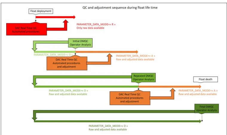
DMQC, which improves initial accuracy considerably, should be performed as soon as a sufficient number profiles have been returned (typically after 5–10 cycles). The sequence of DMQC actions and its impact during float’s life time is illustrated in
Figure 4. During a delayed mode assessment, for either core or BGC data, data from a float are rigorously examined in a multi-parameter context, which typically includes some level of comparative analysis to regional reference data and climatology (e.g., Wong et al., 2003; Owens and Wong, 2009; Johnson et al., 2017). In many cases, any necessary data adjustments (gain, drift, offset) derived by the delayed-mode operator during such an assessment can be fed back into the incoming data stream in real-time, producing real-time adjusted data. The data stream associated with each float parameter, whether real-time (R), real-time-adjusted (A), or delayed-mode (D), is recorded within the PARAMETER_DATA_MODE variable in the files. The file name prefix contains a “D” if any of the float’s parameters are in delayed-mode. If no parameters exist in delayed-mode (i.e., all parameters are either real time, “R,” or real time adjusted, “A”), then the file name prefix remains “R” (Table 5).
These two data streams are reflected in the BGC-Argo data processing organization and documentation. A total of 9 out of the 11 Argo DACs process BGC-Argo parameters, <PARAMs>. The DACs receive float-transmitted raw or preprocessed sensor data, such as sensor counts or voltages
(termed intermediate or “i”-parameters), and translate them to ocean-state biogeochemical quantities held in Argo “b”-parameter variables (i.e., DOXY, NITRATE or CHLA). This step is the “bread and butter” of a DAC, and all processing formulas are detailed in a “Processing BGC-Argo <PARAM> data at the DAC level” cookbook for each parameter (e.g.,
Table 6, column 2 for an overview) with an update frequency that follows approximately the inclusion of a new sensor into BGC-Argo. Each cookbook document is highly comprehensive, often including sample parameter data processing code and meta-data population examples for a wide range of BGC sensor types and model configurations. It is highly recommended that particular care is taken in following the procedures outlined within the Argo data processing documentation in order to ensure consistency between DACs. Specific questions related to a specific float configuration, should they arise, are typically directed toward the Argo community via the Argo data management list-serve.
It is important to note that the accuracy of “R”-mode BGC data resulting from the cookbook processing is often not suitable for direct usage in scientific applications due to the presence of potentially large initial offsets, the magnitude of which cannot be fully characterized prior to deployment. Therefore, users are warned that raw biogeochemical data should be treated with care, and that often, adjustments are needed before these data can be used for meaningful scientific applications.
FIGURE 4 | Sequence of quality control and adjustment steps during the life time of a float from float deployment to death. The color shading indicates the data mode: “R” real-time data in red, “A” real-time adjusted data in yellow, and “D” delayed-mode data in green. Initial DMQC should be performed soon after deployment (typically after 5–10 cycles). With subsequent DMQC revisits (on an annual basis), adjustments become more reliable (indicated by the green shading).
TABLE 5 | Example of the file naming scheme for a float with WMO
number 5904395. Note that either a “real-time” c-/b-/s-file or a “delayed-mode” c-/b-/s-file exists, not both. The all-cycle file contains all available cycles for the float.
Kind of file c-files b-files s-files “real-time” file R5904395_001.nc BR5904395_001.nc SR5904395_001.nc1
“delayed-mode” D5904395_001.nc BD5904395_001.nc SD5904395_001.nc file
all-cycle file 5904395_prof.nc NA 5904395_Sprof.nc
1The data mode indicated on single-cycle s-files reflects the highest level of
parameter data mode indicated in core and b-files.
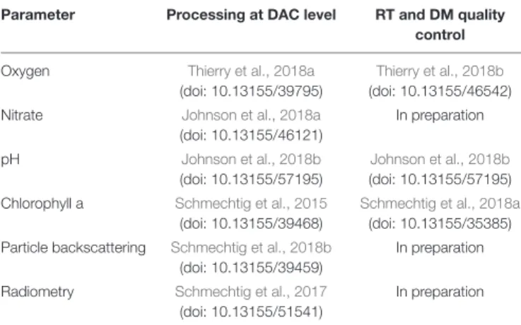
TABLE 6 | Overview about BGC-Argo documentation for the 6 core BGC variables.
Parameter Processing at DAC level RT and DM quality control Oxygen Thierry et al., 2018a
(doi: 10.13155/39795)
Thierry et al., 2018b
(doi: 10.13155/46542) Nitrate Johnson et al., 2018a
(doi: 10.13155/46121) In preparation pH Johnson et al., 2018b (doi: 10.13155/57195) Johnson et al., 2018b (doi: 10.13155/57195) Chlorophyll a Schmechtig et al., 2015
(doi: 10.13155/39468)
Schmechtig et al., 2018a
(doi: 10.13155/35385) Particle backscattering Schmechtig et al., 2018b
(doi: 10.13155/39459)
In preparation
Radiometry Schmechtig et al., 2017
(doi: 10.13155/51541)
In preparation
Header BGC-Argo QC manual:Schmechtig et al., 2016(doi: 10.13155/40879).
This is why there is a second BGC-Argo document for each parameter, an “Argo quality control manual for<PARAM> data” (e.g., Table 6, column 3 for an overview). The QC manuals go hand in hand with the processing cookbooks. However, their update frequency is driven by scientific evolution. Each QC manual details parameter-specific QC tests applicable to “R”-, “A”-, and “D”-mode data. Moreover, they describe the adjustment procedures required to make the biogeochemical quantities scientifically usable, both in delayed-mode “D” (using potentially complex methods) and in real-time adjusted mode “A” (using robust and operationally feasible methods that do not require human intervention and are implementable at the DAC level). A real-time “A”-mode adjustment for incoming data can be based on a delayed-mode “D” adjustment of existing data. Both “D”-and “A”- mode data fill the<PARAM>_ADJUSTED data fields as well as the corresponding SCIENTIFIC_CALIB data fields. <PARAM>_ADJUSTED_ERROR estimates are mandatory for “D”-mode data and highly recommended for “A”-mode. If not stated otherwise, they represent a 1 sigma uncertainty. Note that raw intermediate parameters are not quality controlled and that only the derived BGC parameters receive QC.
Data Flow Guidance
Real-time operations, including the reception of float-transmitted files, decoding and conversion to biogeochemical parameters, application of real-time adjustments, as well as the
creation of Argo netcdf files and transfer to the GDACs, are performed at each DAC.
Delayed-mode operations (data adjustment to science quality by an expert of the parameter, control and/or correction of QC flags, visual QC, incorporation of the results into the Argo files, and feedback of “D”-mode data files to the responsible DAC) fall exclusively into the responsibility of the float PI, and it is the float PI’s task to allocate appropriate capacity and funds to perform these tasks for the lifetime of the float.
Note that both the sharing of data and providing delayed-mode quality controlled data is mandatory for a float running under the Argo label and its associated IOC regulations (Argo Steering Team, 20184,5).
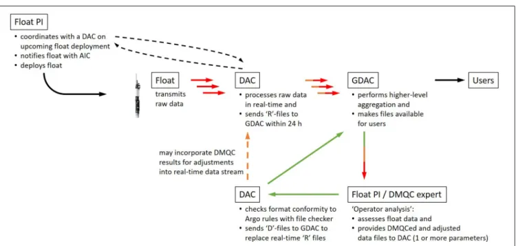
Defining the proper pathway for processing of a BGC float (Figure 5) could take different forms, but having a system identified prior to deployment is advised. Suggested steps would include:
(1) Identification of a pre-existing DAC to perform the real-time processing and submission of incoming float data in the proper Argo data-file formats.
(2) Identification of personnel to perform DMQC for core, and BGC data (This could include the float PI, or external experts. Given the richness of parameters, this does not need to be localized at a single laboratory). An operational workflow must be established such that any data adjustments resulting from DMQC efforts (2) are effectively fed back into the processing and submission scheme (1). Key resources for aiding in the operational implementation of both real-time and delayed-mode processing, including specifics related to conversion of raw sensor output into scientific quantities as well as quality control and adjustment procedures, can be found at http://www.argodatamgt.org/Documentation, and are summarized in Table 6. Code/software that can aid in the QC process are, for example, the SOCCOM Assessment and Graphical Evaluation tools6 or Scoop-Argo
(Detoc et al., 2017).
The Argo Data Management Team coordinates and approves the BGC-Argo processing and QC/adjustment approaches on the network level through the two key documents, the BGC-Argo cookbooks and the QC manuals, in order to ensure consistency between DACs/float operators and to incorporate and approve new scientific approaches.
Finally, as highlighted in the previous parts, the BGC-Argo data flow implies a lot of transformation of the data files from the real time to the delayed mode status. A file checker is developed and made available to the Argo community7 so
that before submitting modified files to the GDAC, anyone can check that their files are compliant with the Argo rules and documentations.
4http://www.argo.ucsd.edu/What_is_Argo_float.html 5http://www.argo.ucsd.edu/Argo_Framework.html
6https://github.com/SOCCOM-BGCArgo/ARGO_PROCESSING 7http://usgodae.org/pub/outgoing/argo/etc/FileChecker/
FIGURE 5 | Pathway for processing of BGC-Argo float data with interactions and data flow between different players: float principal investigator (PI), data acquisition center (DAC), global DAC (GDAC), delayed-mode quality control operator, and users. The upper row indicates the real-time data stream, while the lower loop shows the delayed-mode data stream. All data are made available to the users via the two GDACs, ftp://ftp.ifremer.fr/ifremer/argo/ or ftp://usgodae.org/pub/outgoing/argo/.
4. DATA USAGE
File Types: Core-, b- and s-Files
There are three types of Argo files on the GDACs: (1) the core- or c-files; (2) the biogeochemical- or b-files; and (3) the simplified-or s-files (Table 5).
The c-files contain the float pressure, temperature and salinity data. The b-files contain the pressure and all BGC data, including the raw intermediate sensor data and the computed ocean-state variables. The c- and b-files record the raw float-transmitted data. However, there are subtle differences between how various float types/manufacturers/firmware transmit their data. For example, NKE PROVOR floats transmit the exact pressure reading at the moment a BGC parameter is sampled, while APEX floats transmit only the pressure at which a sequence of sensors samplings are initiated, i.e., all samples around a pressure level are reported with the same pressure despite being sampled at slightly different moments.
To (a) give a homogeneous structure to all BGC-Argo floats, independent of the level of detail of their transmitted data, (b) account for vertical displacement between T/S and BGC sensors due to different vertical position on the float, (c) co-align quasi-concurrent BGC observations for easy multi-parameter analysis, the c- and b- profile data are synthesized to produce the so-calledsimplified- or s-profiles at the GDACs (Bittig et al., 2019). The s-files contain both the T/S profile data and the ocean-state BGC parameter data interpolated onto one pressure axis. These are relatively new files in the Argo data system and will eventually replace the previous GDACmerge- or m-files, which were a simple concatenation of the T/S and BGC data without vertical interpolation.
Data Modes and Quality Flags
Biogeochemical-Argo data come in one of three data modes (Figure 6). These are given within the PARAMETER_DATA_ MODE variable and provide an indication on the data quality to expect:
“R” or “Real-Time”: Designates data of the real-time data stream that is unadjusted. These data were converted by the DAC from raw transmitted sensor data to an ocean state BGC parameter without any further adjustments. While real-time QC was applied to remove gross outliers, these data should be treated with care, as adjustments are often needed before these data can be used for meaningful scientific applications.
“A” or “Real-Time Adjusted”: Designates data of the real-time data stream that is adjusted in real-real-time. These data were converted by the DAC from raw transmitted sensor data to an ocean state BGC parameter and subsequently received an adjustment in an automated manner. While accuracy of such data isa priori much better than for “R”-mode data and should allow scientific use, no guarantee is given that they are free of sensor malfunction or other flaws (e.g., unidentified biofouling causing drifts/offsets). They can be provided with an uncertainty estimate (typically 1σ).
“D” or “Delayed-Mode (Adjusted)”: Designates data of the delayed-mode data stream that have been adjusted (Note: Could be x + 0 if the raw data are fine) and quality controlled (e.g., flagging of data biased by biofouling; see details in QC manuals, Table 6) by a scientific expert. “D”-mode data are validated for scientific exploitation and represent the highest quality of data at the given point in time. They are provided with an uncertainty estimate (typically 1σ).
FIGURE 6 | Summary of data mode characteristics.
Note that BGC-Argo is an evolving network, which is also true for its data. This means that “D”-mode data do not always stay the same. They may well change when better methods, climatologies, or longer float time-series become available.
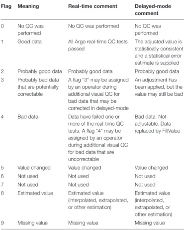
In addition, each sample has a corresponding quality flag. The QC flags and their meaning are defined in Argo reference table 2 (Wong et al., 2019), reproduced in Table 7. The QC flags are an essential part of the data.
Data Access Guide
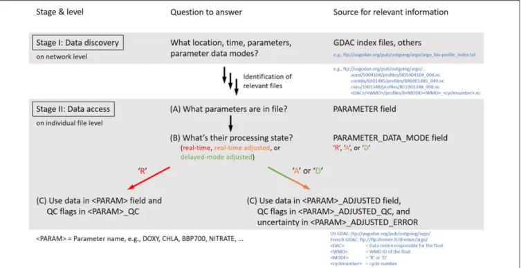
Data access begins with the search for appropriate floats and profiles. A good starting point is the exploration of various Argo index files at the GDACs, e.g., argo_bio-profile_index.txt lists profile location, time, parameters, and parameter data modes for floats at the GDACs.
Once identified, data access for individual files should follow: (1) What parameters are in the file? (→ PARAMETER
variable),
(2) What’s the processing state (“R,” “A,” or “D”) of the respective parameter? (→ PARAMETER_DATA_MODE variable), and
(3) Depending on (2), the actual access to both the parameter values and their quality flags (<PARAM> and <PARAM>_QC variables for “R,” <PARAM>_ ADJUSTED, <PARAM>_ADJUSTED_QC, and <PARAM>_ADJUSTED_ERROR for “A” and “D”) (Figure 7).
Data Sources
Argo data can be accessed by either one of the two GDACs (ftp: //ftp.ifremer.fr/ifremer/argo or ftp://usgodae.org/pub/outgoing/ argo) or through the Argo GDAC doi (Argo, 2000). To allow traceability of research, the Argo doi may be sub-referenced to one of the monthly snapshots with its own doi key8.
Other sources may aggregate Argo data for specific purposes (e.g., regional). However, only those sources should be used where the data origin is traceable and
8http://www.argo.ucsd.edu/Acknowledging_Argo2.html
TABLE 7 | “Argo reference table 2” with meanings of quality control flags from the Argo QC manual (Wong et al., 2019).
Flag Meaning Real-time comment Delayed-mode comment 0 No QC was
performed
No QC was performed No QC was performed 1 Good data All Argo real-time QC tests
passed
The adjusted value is statistically consistent and a statistical error estimate is supplied 2 Probably good data Probably good data Probably good data 3 Probably bad data
that are potentially correctable
A flag “3” may be assigned by an operator during additional visual QC for bad data that may be corrected in delayed-mode
An adjustment has been applied, but the value may still be bad
4 Bad data Data have failed one or more of the real-time QC tests. A flag “4” may be assigned by an operator during additional visual QC for bad data that are uncorrectable
Bad data. Not adjustable. Data replaced by FillValue
5 Value changed Value changed Value changed 6 Not used Not used Not used 7 Not used Not used Not used 8 Estimated value Estimated value
(interpolated, extrapolated, or other estimation) Estimated value (interpolated, extrapolated, or other estimation) 9 Missing value Missing value Missing value
transparent, i.e., a given profile can be unambiguously traced back to the Argo data system’s profile (i.e., has float WMO, cycle number, and file update date or Argo snapshot doi).
Data Acknowledgment
Being part of Argo, BGC-Argo data are freely available without restrictions. Still, Argo (and thus BGC-Argo) asks users to acknowledge their usage by stating
FIGURE 7 | Workflow how to discover (stage I) and access BGC-Argo data (stage II).
“These data were collected and made freely available by the International Argo Program and the national programs that contribute to it (http://www.argo.ucsd.edu, http://argo.jcommops.org). The Argo Program is part of the Global Ocean Observing System.” and by citation of the appropriate Argo doi.
In many cases, however, the float PI or operator may have more detailed knowledge about a BGC-Argo float or the area of operation. For regional studies or studies involving just a limited number of float programs, it is recommended to contact the respective float PI or programs.
VARIABLE-SPECIFIC ASPECTS
Descriptions of biogeochemical sensors available on BGC-Argo floats are provided below. Note that accompanying temperature, salinity and pressure data are required to support the transformation of raw data returned from a respective BGC sensor into a meaningful BGC quantity. The CTD instrumentation used on typical Argo floats is described in
Roemmich et al. (2004). An outline of the associated core-Argo variable quality control procedures can be found inWong et al. (2019). Such details will not be summarized here, as they are beyond the scope of this paper.
For all sensors it is good practice to always transmit the raw data, following the sensors’ sensing principle (e.g., temperature, phase shift, spectral absorption, currents, counts). The processing capabilities of the data management system will always be superior to on-board capabilities and raw data can be
reprocessed at any time as improved algorithms become available as long as the calibration information is available. Figure 8 gives some examples of BGC sensor attachments on different float platforms.
Oxygen
Dissolved oxygen (O2) is a key variable of ocean biogeochemistry
(e.g., biological production, respiration) and a valuable tracer for ocean physics (e.g., ventilation, deoxygenation). It was the first biogeochemical variable to be measured by Argo (Körtzinger et al., 2004;Gruber et al., 2007).
The preferred type of sensor to measure O2 from floats
are oxygen optodes as they are robust and have low power consumption (order 1.5 J per sample). They are based on luminescence quenching of a chemical immobilized in a gas-permeable sensing membrane, which is in contact with seawater. This has two consequences: (1) Oxygen optodes sense the seawater oxygen partial pressure, pO2, and (2) they show an
oxygen time response due to re-equilibration between sensing membrane and seawater (Bittig et al., 2018a). Typical response times are between 5 and 100 s, depending on sensor and setting, and can be reduced if the optode is in a pumped flow (Bittig et al., 2014; Bittig and Körtzinger, 2017). Response time correction algorithms require the measurement times of optode samples to be stored and transmitted by the float’s firmware. The Argo data system is able to store this information alongside the sensor data (Bittig et al., 2017).
Only oxygen optodes with individual multi-point calibration should be used, as “foil-batch” calibrations perform worse in characterizing the O2-temperature-response (Bittig et al., 2018a)