HAL Id: tel-01997554
https://tel.archives-ouvertes.fr/tel-01997554v4
Submitted on 28 Jul 2019
HAL is a multi-disciplinary open access
archive for the deposit and dissemination of sci-entific research documents, whether they are pub-lished or not. The documents may come from teaching and research institutions in France or abroad, or from public or private research centers.
L’archive ouverte pluridisciplinaire HAL, est destinée au dépôt et à la diffusion de documents scientifiques de niveau recherche, publiés ou non, émanant des établissements d’enseignement et de recherche français ou étrangers, des laboratoires publics ou privés.
vehicles
Gia-Minh Hoang
To cite this version:
Gia-Minh Hoang. Cooperative multisensor localization for connected vehicles. Electronics. Telecom ParisTech, 2018. English. �tel-01997554v4�
EDITE - ED 130
Doctorat ParisTech
T H È S E
pour obtenir le grade de docteur délivré par
TELECOM ParisTech
Spécialité « Électronique et Communications »
présentée et soutenue publiquement par
Gia Minh HOANG
préparée au CEA-Leti et à EURECOM le 19 février 2018
Localisation multicapteurs coopérative
pour les véhicules connectés
Directeur de thèse : Jérôme HÄRRI,EURECOM
Co-directeur de thèse : Dirk SLOCK,EURECOM
Co-encadrement de la thèse : Benoît DENIS,CEA-Leti
Jury
M. Giovanni PAU,Professeur, Université Pierre et Marie Curie Président
M. Henk WYMEERSCH,Professeur, Chalmers University of Technology Rapporteur
Mme. Valérie RENAUDIN,Directrice de Recherche (HDR), IFSTTAR Rapporteur
M. Moe Z. WIN,Professeur, Massachusetts Institute of Technology Examinateur
M. Thomas ENGEL,Professeur, Université du Luxembourg Examinateur
TELECOM ParisTech
EDITE - ED 130
T H E S I S
in partial fulfillment of the requirements for the degree of Doctor of Philosophy
TELECOM ParisTech
Specialty « Electronics and Communications »
publicly defended by
Gia Minh HOANG
prepared at CEA-Leti and EURECOM on February 19, 2018
Cooperative multisensor localization
for connected vehicles
Thesis director : Jérôme HÄRRI,EURECOM
Thesis co-director : Dirk SLOCK,EURECOM
Thesis advisor : Benoît DENIS,CEA-Leti
Jury members
Mr. Giovanni PAU,Professor, Pierre and Marie Curie University President
Mr. Henk WYMEERSCH,Professor, Chalmers University of Technology Reviewer
Mrs. Valérie RENAUDIN,Director of Research (HDR), IFSTTAR Reviewer
Mr. Moe Z. WIN,Professor, Massachusetts Institute of Technology Examiner
Mr. Thomas ENGEL,Professor, University of Luxembourg Examiner
TELECOM ParisTech
This thesis work was an enjoyable and unforgettable experience of my life. I would like to sincerely thank all who supported, encouraged, and helped me until I accomplished the Ph.D. degree. I could not have reached this milestone without them.
First and foremost, I would like to express my sincere gratitude to my thesis supervisor, Dr. Benoˆıt Denis, for the opportunity to work in such an interesting project and for his encouragement, guidance, and understanding during the last three years. I would also like to thank my thesis directors, Prof. J´erˆome H¨arri and Prof. Dirk Slock, for their valuable contributions that significantly improved the quality of my work. From the three of them, I have learned how to conduct a research, think rigorously, formulate problems, and present my results in an interesting way. I really enjoyed our discussions every week when fancy ideas were raised. Moreover, I am thankful for the freedom they left me in pursuing my research activities, as well as for their faith in my work. I have had a really nice time with the three of them and I really hope that we will collaborate in the future. I would like to thank Prof. Giovanni Pau for honoring me by serving as president of my oral committee. Furthermore, I am very grateful to my reviewers Dr. Val´erie Renaudin and Prof. Henk Wymeersch for their careful review of my work, and to my examiners Prof. Moe Z. Win and Prof. Thomas Engel for their helpful advice and feedback.
I would like to express my special appreciation to all the colleagues from the Smart Objects Communication Lab (previously, the Study & Specification of Communication Systems Lab) at CEA-Leti and from the Communication Systems Department at EURE-COM, as well as to the partners involved in the HIGHTS collaborative project, for their friendship, support, joint work, and fun. I have truly enjoyed getting to know and work with each of them, and I am especially grateful to Truong, Quynh, Jimmy, Yoann, Lu-dovic, Gourab, Mois´es, Remun, Ioan-Sorin, Florian, Fatima, Jessica, Iulia, Robin, David, Elodie, Kersane, Luiz, Rida, Mickael, Val´erian, Antonio, Luc, Nicolas, Fran¸cois, Sylvie,
Valentin, Jean-Baptiste, Benoˆıt, Manuel, Sebastian, Christophe, Irfan, Raj, Nil, Alireza, Ronald, Marcus, and Mattia. I am also very grateful to Sandrine and Audrey for helping me with administrative procedures as well as Vincent, Dimitri, Dominique, Fabien and for supporting me in attending the conferences.
Finally, I dedicate my thesis to my family members for their unconditional love, en-couragement, and support throughout my life. I also want to thank my lovely girlfriend Thu H`a, for all her love, patience, and support.
This work has been performed in the frame of the HIGHTS project, which is funded by the European Commission (636537-H2020).
Cooperative Intelligent Transport Systems (C-ITS) applications assume the availability of a reliable and accurate positioning system. Even if suitable to most Day-1 applications (e.g., route navigation), the Global Navigation Satellite System (GNSS) accuracy, reli-ability and availreli-ability are clearly not sufficient for more demanding Day-2 applications (e.g., highly autonomous driving (HAD), advanced safety services including vulnerable road users (VRUs) warning, etc.), which would require a consistent sub-meter localization accuracy regardless of operating conditions. To bridge this gap, Cooperative Localization (CLoc) has been recently identified as a promising strategy. Accordingly, mobile nodes can help each other by exchanging location data (typically, their own position estimates or raw GNSS data), acquiring range-dependent metrics over their respective radio links and finally, fusing the various sources of information. However, conventional CLoc solutions may be partly unsuitable within the context of vehicular ad hoc networks (VANETs), which comes along with unprecedented challenges such as specific mobility patterns, prac-tical operating trade-offs with complexity and vehicle-to-vehicle (V2V) communication capabilities, or even fusion optimality when multiple measurement modalities are avail-able at the vehicles. Thus, one central related research question is as follows: “Can the Day-2 sub-meter localization accuracy be met through CLoc strategies between connected vehicles?”
In this thesis, following a gradually complex approach, we aim at evaluating how and in which conditions position information from neighboring vehicles and/or associated V2V measurements may improve localization accuracy and resilience. We first develop a generic fusion-based CLoc framework, which can rely on various vehicle-to-everything (V2X) and embedded sensor technologies. We then apply this framework to the standard ITS-G5 Cooperative Awareness Messages (CAMs), and show that it is possible to benefit from neighboring position information and from received signal strength-based range estimates
to enhance local accuracy. On this occasion, we also make concrete proposals to handle messages/data asynchronism (through mobility-based predictions), as well as to reduce both complexity and V2V communication footprint (through links/neighbors selection, messages approximation and transmission control). Next, we extend this framework so as to integrate more accurate V2V measurements based on the impulse radio ultra-wide bandwidth (IR-UWB) technology, while dealing with fusion filter overconfidence and error propagation issues. Finally, under even more challenging conditions with GNSS depraved neighbors or in tunnel conditions, we considered the assistance of extra onboard sensors (inertial measurement unit (IMU), wheel speed sensor (WSS), camera-based lane detector, etc.), as well as static roadside units (RSUs). The proposed framework and methodology show to typically improve the localization accuracy from 2 m to below 30 cm in 80% of the cases. The proposed framework has been tested analytically and through simplified simulations first, then on realistic mobility data, and finally on real data from a small-scale field test.
Acknowledgement v
Abstract vii
Contents ix
List of Figures xv
List of Tables xxiii
Acronyms and Abbreviations xxv
1 Introduction 1
1.1 Application Context . . . 1
1.2 Motivations and Objectives . . . 2
1.3 Thesis Contributions and Outline . . . 4
2 State of the Art in Vehicular Localization 7 2.1 Introduction. . . 7
2.2 Cooperative-ITS . . . 7
2.2.1 V2X Applications . . . 7
2.2.2 V2X Messages and Services . . . 10
2.2.3 V2X Technologies . . . 12
2.3 Vehicular Localization and Navigation Systems . . . 15
2.3.1 Satellite-Based Localization . . . 15
2.3.2 Sensor-Based Localization . . . 20
2.3.3 Infrastructure-Based Localization . . . 27
2.3.4 Cooperative Localization . . . 27 ix
2.4 Gap Analysis and Challenges . . . 31
3 V2V Cooperative Localization 37 3.1 Introduction and Related Works . . . 37
3.2 Problem Formulation and System Model . . . 39
3.2.1 Gauss–Markov Mobility Model . . . 42
3.2.2 Observation Model . . . 44
3.3 Resynchronization of Cooperative Information. . . 45
3.4 GNSS/ITS-G5 Data Fusion Based on Particle Filter . . . 47
3.5 Low-Complexity Link Selection . . . 48
3.5.1 Link Selection Criteria . . . 50
3.5.2 Link Selection Algorithm . . . 52
3.6 Numerical Results . . . 53
3.6.1 Simulation Settings. . . 53
3.6.2 Scenario Evaluation . . . 56
3.7 Summary . . . 60
4 Wireless Channel Impacts on V2V Cooperative Localization 63 4.1 Introduction and Related Works . . . 63
4.2 Problem Formulation. . . 65
4.2.1 Correlations in Observation Noises . . . 65
4.2.2 Limited V2V Message Payload and Channel Capacity . . . 68
4.3 Mitigation of Observation Noise Correlations . . . 70
4.3.1 Signal Level Mitigation . . . 70
4.3.2 Adaptive Fusion Rate . . . 74
4.3.3 Numerical Results . . . 75
4.4 Message Approximation and Transmission Control Strategy . . . 85
4.4.1 Parametric Message Approximation . . . 85
4.4.2 Jointly Payload, Rate, and Power Control . . . 87
4.4.3 Numerical Results . . . 88
5 Hybrid V2V Cooperative Localization 95
5.1 Introduction and Related Works . . . 95
5.2 Problem Formulation. . . 98
5.2.1 IR-UWB Ranging Protocol and Model . . . 98
5.2.2 Fusion Filter Overconfidence and Error Propagation . . . 101
5.3 Selective and Refined Cooperative Localization . . . 105
5.3.1 Bias Mitigation Phase . . . 105
5.3.2 Accuracy Refinement Phase . . . 106
5.4 Adaptive Bayesian Dithering . . . 106
5.5 Numerical Results . . . 109
5.5.1 Simulation Settings. . . 109
5.5.2 Performances of Fusion Scheduling with Heterogeneous GNSS Ca-pabilities . . . 111
5.5.3 Performances of Adaptive Bayesian Dithering with Homogeneous GNSS Capabilities . . . 114
5.6 Summary . . . 116
6 Hybrid V2X Multisensor Cooperative Localization 119 6.1 Introduction and Related Works . . . 119
6.2 Problem Formulation. . . 120
6.2.1 Poor Relative Geometry Conditions along the Cross-Track Direction 120 6.2.2 Localization Error Accumulation and Propagation . . . 121
6.3 Multisensor Fusion for Improved Cross-Track Localization . . . 122
6.3.1 Integration of Additional IMU and Wheel Odometry Sensors . . . . 122
6.3.2 Integration of Additional Camera-Based Lane Detection . . . 124
6.4 V2X Cooperative Localization in GNSS-Denied Environments . . . 124
6.4.1 V2I/V2V Cooperative Localization . . . 124
6.4.2 GNSS Repeater-Aided V2V Cooperative Localization . . . 125
6.5 Numerical Results . . . 126
6.5.1 Simulation Settings. . . 126
6.5.2 Two-Lane Highway Scenario . . . 128
6.6 Summary . . . 135
7 Validations through More Realistic Simulations and Experimental Data137 7.1 Introduction. . . 137
7.2 Offline Validation Based on Mobility Traces . . . 138
7.2.1 Simulation Settings. . . 138
7.2.2 Results . . . 140
7.3 Offline Validation Based on Experimental Data . . . 142
7.3.1 Experimental Settings . . . 142
7.3.2 Results . . . 145
7.4 Summary . . . 148
8 Conclusions and Perspectives 151 8.1 Conclusions . . . 151
8.2 Perspectives . . . 154
9 R´esum´e Etendu des Travaux de Th`ese 157 9.1 Introduction. . . 157
9.2 Probl´ematique et Enjeux. . . 159
9.3 Analyse de l’Etat de l’Art et M´ethodologie Suivie . . . 163
9.4 Localisation Coop´erative `a partir de Communications V2V . . . 166
9.4.1 Architecture G´en´erique de Fusion de Donn´ees CLoc . . . 166
9.4.2 S´election de Liens `a Faible Complexit´e . . . 168
9.4.3 Limitation de la Corr´elation des Bruits d’Observation . . . 169
9.4.4 Approximation des Messages et Contrˆole des Emissions . . . 174
9.5 Localisation Coop´erative Hybride `a partir de Communications V2V et de Mesures de Distances Pr´ecises . . . 178
9.6 Localisation Coop´erative Hybride Multi-Capteurs . . . 179
9.7 Validations . . . 181
9.7.1 Simulations en pr´esence d’un Trafic R´ealiste. . . 181
9.7.2 Premi`eres Exp´erimentations . . . 183
A Personal List of Publications and Contributions 187 A.1 Journal Publications . . . 187
A.2 Conference Publications . . . 187
A.3 Deliverables . . . 188
A.4 Technical Report . . . 189
A.5 Poster Presentations (with Proceedings-Entry) . . . 189
B General Taxonomy of Localization Algorithms 191 B.1 Direct versus Two-Step . . . 191
B.2 Centralized versus Distributed . . . 192
B.3 Absolute versus Relative . . . 192
B.4 Range-Based versus Range-Free . . . 192
B.5 Noncooperative versus Cooperative . . . 193
B.6 Deterministic versus Probabilistic . . . 193
B.7 Standalone Sensor versus Multisensor Fusion . . . 194
C Location-dependent Radio Metrics and Related Technologies 195 C.1 Received Signal Strength Indicator . . . 195
C.2 Time of Arrival . . . 197
C.3 Time Difference of Arrival . . . 199
C.4 Angle of Arrival. . . 200
C.5 Phase Difference of Arrival . . . 201
C.6 Hybrid Measurements . . . 201
C.7 Fingerprinting. . . 202
D Multisensor Fusion Methods 205 D.1 Architectures for Multisensor Fusion . . . 205
D.2 Statistical Estimators . . . 206
D.2.1 Non-Bayesian Estimators . . . 207
D.2.2 Bayesian Estimators . . . 207
D.3 Bayesian Filters . . . 208
D.4 Kalman Filter . . . 209
D.5 Extended Kalman Filter . . . 210
D.6 Unscented Kalman Filter . . . 211
E Performance Metrics 215
F Generation of Correlated Observations 217
2.1 Examples of Day-1 applications and the scenarios V2V communications can
address. . . 8
2.2 The C2C-CC applications road map. . . 9
2.3 The C-ITS protocol stack. . . 10
2.4 CAM structure (ETSI EN 302 637-2). . . 11
2.5 Effect of DOP in satellite-based positioning systems. . . 18
2.6 Integrated GNSS/INS system architectures. . . 23
2.7 Dataflow of CLoc in an “ego” vehicle. . . 28
3.1 (a) Cooperative cars periodically exchange CAMs to maintain awareness of each other and to support distributed CLoc. (b) “Ego” car receiving asynchronous CAMs from one-hop “virtual anchors” to perform distributed CLoc. . . 38
3.2 Example of space-time schematic managed by the “ego” i whose neighbors are vehicles j and l. . . 40
3.3 Example of CLoc space-time data management at the “ego” vehicle i with respect to its neighboring vehicle j. . . 46
3.4 Sets of selected cooperative neighbors (green) with respect to the “ego” vehicle (red), following (a) non-Bayesian and (b) Bayesian CRLB criteria. . 49
3.5 Topology of the evaluated VANET and associated configurations for S1 (urban canyon) and S2 (different classes of GNSS receiver) for the evaluation of link selection algorithms. . . 54
3.6 Localization RMSEs (over vehicles) as a function of time for non-CLoc, CLoc with exhaustive fusion, and CLoc with selective fusion when GNSS quality varies depending on the geographic area (S1).. . . 56
3.7 Trade-off between the number of required packets for CLoc and the localiza-tion RMSE (over vehicles and time) with or without selective cooperalocaliza-tion in different GNSS conditions (S1). . . 57
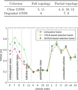
3.8 Localization RMSEs (over the full trajectory) for different fusion schemes with and without selective cooperation at each vehicle (S2). . . 59
3.9 Empirical CDFs of localization errors for different fusion schemes with and without selective cooperation at 4 representative vehicles with distinct GNSS quality classes (S2). . . 59
4.1 Possible shadowing autocorrelations/cross-correlations on/between V2V link(s) having dual mobility in VANETs.. . . 67
4.2 Example of awareness data flow in PF-based CLoc framework for two ve-hicles i and j. . . 69
4.3 Simplified 2-D position representations including nonparametric and para-metric approaches. . . 69
4.4 Impacts of asynchronous position estimates and CAM transmissions on the information fusion. . . 74
4.5 Illustration of the adaptive sampling techniques simply deceasing the coop-erative fusion rate to collect uncorrelated RSSI measurements. . . 75
4.6 Topology of the evaluated VANETs and related attributes in (a) high-way/tunnel and (b) urban canyon scenarios. . . 76
4.7 Localization performance comparison of different schemes assuming corre-lated GNSS noise and i.i.d. shadowing in the highway scenario. . . 79
4.8 Localization performance comparison of different schemes assuming i.i.d. GNSS noise and correlated shadowing in the highway scenario. . . 80
4.9 Localization performance comparison of different schemes assuming corre-lated GNSS noise and correcorre-lated shadowing in the highway scenario. . . 81
4.10 RMSE comparison of different filter/fusion strategies divided into three groups: conventional approaches (top), proposed approaches (middle), and optimal (unrealistic) approaches (bottom) in the highway scenario. . . 82
4.11 Localization performance comparison of different schemes assuming corre-lated GNSS noise and correcorre-lated shadowing in the urban canyon scenario. . 83
4.12 Localization performance comparison of different schemes assuming loss of GNSS signal and correlated shadowing in the tunnel scenario. . . 84
4.13 Standard CAM transmission policy (10 Hz) in (a) versus adjusted mixed CAM traffic in (b). . . 88
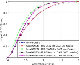
4.14 Empirical CDFs of localization errors for different schemes with respect to fused modalities, message approximation and transmission control. . . 91
5.1 “Ego” car receiving CAMs and exchanging ranging frames RFRAME from/with single-hop “virtual anchors” to perform distributed CLoc. . . 97
5.2 Beacon-aided TDMA MAC SF format supporting the localization function-ality (SF duration of 200 ms). . . 99
5.3 Example of the A-B protocol scheme in a SF for ranging within a VANET of 3 vehicles. . . 101
5.4 Illustration of particles depletion when fusing accurate IR-UWB ranges with GNSS and no depletion when using inaccurate RSSIs and GNSS in a boot-strap PF. . . 103
5.5 Illustration of bias propagation while fusing accurate IR-UWB ranges with GNSS in a bootstrap PF. . . 104
5.6 Illustration of 2 solutions for particles depletion when fusing accurate IR-UWB ranges with GNSS positions in a bootstrap PF. . . 107
5.7 VANET scenario evaluated in highway scenario for the mitigation of filter overconfidence and error propagation. . . 109
5.8 Empirical CDFs of localization errors considering degraded GNSS vehicles for different PF fusion schemes and different measurements/technologies for the mitigation of filter overconfidence and error propagation. . . 112
5.9 Localization RMSEs considering degraded GNSS vehicles as a function of time for different PF fusion schemes and different measurements/technologies for the mitigation of filter overconfidence and error propagation. . . 112
5.10 Empirical CDFs of localization errors considering non-degraded GNSS vehi-cles for different PF fusion schemes and different measurements/technologies for the mitigation of filter overconfidence and error propagation. . . 113
5.11 Empirical CDF of localization errors for different fusion techniques, schemes, and measurements/technologies for the mitigation of filter overconfidence and error propagation (including accurate V2V range measurements). . . . 115
5.12 Average 1-σ estimation errors perceived by fusion filters for different fusion techniques, schemes, and measurements/technologies for the mitigation of filter overconfidence and error propagation. . . 115
5.13 1-σ estimation errors perceived by fusion filters for each vehicle during the first 2 seconds for the fused GNSS+IR-UWB ranges using EKF (top), con-ventional PF (middle), and PF with adaptive dithering (bottom).. . . 116
6.1 Example of expected CLoc localization performance in a 4-node VANET. . 121
6.2 1-σ along-track (top) and cross-track (bottom) errors perceived by fusion filters for each vehicle during the first 3 seconds for non-CLoc (IMU/WSS) and pure CLoc (IMU/WSS/UWB) in a tunnel scenario. . . 122
6.3 Example of unconstrained (partially violating LCs) versus constrained (sat-isfying LCs) positional beliefs. . . 125
6.4 Evaluated VANET and related attributes in (a) two-lane highway scenario and (b) 1000-m straight tunnel scenario. . . 127
6.5 Empirical CDFs of x-axis (along-track/left) and y-axis (cross-track/right) localization errors for different fusion schemes in the two-lane highway sce-nario. . . 128
6.6 Empirical CDFs of overall localization errors for different fusion schemes in the two-lane highway scenario. . . 128
6.7 Empirical CDFs of localization errors for DR (IMU+WSS), IR-UWB V2V CLoc, and V2X CLoc (with IR-UWB V2V and ITS-G5 or IR-UWB V2I) in the tunnel scenario. . . 131
6.8 Empirical CDFs of localization errors for IR-UWB V2X CLoc, GNSS-repeater-aided IR-UWB V2V CLoc, and LCs (with DR only) in the tunnel scenario. . . 132
6.9 Empirical CDFs of localization errors for V2X CLoc (with IR-UWB V2I or ITS-G5 V2I (massive infrastructure) with and without LCs) and ideal GNSS-repeater-aided IR-UWB V2V CLoc in the tunnel scenario. . . 133
6.10 Impact of the RSU deployment on IR-UWB V2X CLoc’s localization accu-racy in the tunnel scenario. . . 134
7.1 Focused geographic area of Bologna city used in calibrated SUMO simula-tions, with mixed urban environments. . . 139
7.2 Empirical CDFs of localization errors of each vehicle in case of CLoc (GNSS+WSS +IMU+UWB) and non-CLoc (GNSS+WSS+IMU) for the Bologna scenario.141
7.3 Empirical CDFs of aggregated localization errors over all 10 vehicles in case of CLoc (GNSS+WSS+IMU+UWB) and non-CLoc (GNSS+WSS+IMU) for the Bologna scenario.. . . 141
7.4 Relative geometry of the 10 simulated vehicles at t = 130 s and t = 145 s for the Bologna scenario.. . . 142
7.5 Test vehicles involved in the first HIGHTS field trials carried out in Hel-mond: Objective’s BMW, Tass’s Prius and Ibeo’s Passat (left to right). . . 143
7.6 Test site and vehicles’ trajectory in Helmond, Netherlands. . . 143
7.7 Pathloss measurements and approximate large-scale models. In the linear regression, np= 2.5 and σSh = 3.7 dB. . . 144
7.8 Empirical CDFs of localization errors for the first trip of field trials in Helmond. . . 145
7.9 Localization RMSEs of the LDM at IBEO’s “ego” vehicle as a function of time for the first trip of field trials in Helmond. . . 146
7.10 Empirical CDFs of localization errors of the Ibeo’s “ego” vehicle for the first trip of field trials in Helmond with reduced position estimation rates. . 147
7.11 Empirical CDFs of along-track and cross-track errors of the Ibeo’s “ego” vehicle for the first trip of field trials in Helmond, with reduced position estimation rates. . . 147
7.12 Empirical CDF of localization errors for the second trip of field trials in Helmond. . . 148
7.13 Empirical CDF of localization errors of the Ibeo’s “ego” vehicle for the second trip of field trials in Helmond with reduced position estimation rates.148
9.1 (a) V´ehicules ´echangeant p´eriodiquement des messages CAMs permettant d’assurer de nouvelles fonctions de localisation coop´eratives CLoc. (b) V´ehicule local (dit “Ego”) recevant des messages CAMs asynchrones de la part d’“ancres virtuelles” et fusionnant l’ensemble des informations disponibles.161
9.2 Technologies de communication envisageables dans un contexte v´ehiculaire de fusion coop´erative. . . 164
9.3 Technologies de radiolocalisation envisageables dans un contexte v´ehiculaire de fusion coop´erative. . . 165
9.4 Architecture globale de fusion adopt´ee pour la localisation v´ehiculaire coop´erative et technologies associ´ees. . . 165
9.5 Approche graduelle suivie dans le cadre du travail de th`ese, avec ajout progessif de nouvelles modalit´es. . . 166
9.6 Exemple de gestion temporelle des donn´ees CLoc au niveau du v´ehicule “Ego” i (en charge de la fusion) vis-`a-vis du v´ehicule voisin j. . . 167
9.7 Sous-ensemble de voisins s´electionn´es (vert) par le v´ehicule “ego” en charge de la fusion (rouge), selon des crit`eres CRLB (a) non-Bay´esien et (b) Bay´esien.169
9.8 Flotte de 15 v´ehicules (gauche-haut) p´en´etrant dans un canyon urbain of-frant des conditions GNSS homog`enes pour l’ensemble de la flotte (gauche-bas); Erreur RMSE et nombre de messages CAMs re¸cus inject´es dans le processus de fusion ITS-G5 V2V RSSI/GNSS pour des crit`eres de s´election (droite). . . 170
9.9 Flotte de 15 v´ehicules pr´esentant des conditions GNSS h´et´erog`enes (gauche); CDF empirique de l’erreur de positionnement issu de la fusion ITS-G5 V2V RSSI/GNSS, pour des strat´egies de s´election. . . 170
9.10 Auto-corr´elation/Inter-corr´elation des ´evanouissements lents affectant les mesures de puissance re¸cue RSSI sur la base de liens V2V ITS-G5 dans un contexte VANET (avec mobilit´e de l’´emetteur et du r´ecepteur). . . 171
9.11 Illustration de la technique diff´erentielle DM appliqu´ee (a) `a la coordonn´ee GNSS x et (b) aux mesures V2V RSSI. . . 172
9.12 Illustration de la r´eduction d´elib´er´ee du taux de fusion permettant de col-lecter des ´echantillons V2V RSSI non-corr´el´ees. . . 173
9.13 CDF empirique d’erreur de positionnement issu de la fusion ITS-G5 V2V RSSI/GNSS pour diff´erentes strat´egies de d´e-corr´elation des bruits d’observation pour un sc´enario de type autoroute. . . 174
9.14 Flot de donn´ees dans un contexte de fusion coop´erative `a base de filtre particulaire entre deux v´ehicules. . . 175
9.15 Repr´esentations simplifi´ees des positions 2-D dans le cadre d’un filtre par-ticulaire, incluant des approches non-param´etriques et param´etriques. . . . 176
9.16 Proposition de trafic mixte de donn´ees `a l’´emission, incluant des messages CAMs standards et des messages limit´es (Tiny), afin de r´eduire la charge induite sur le r´eseau par les nouvelles fonctions de localisation coop´eratives. 177
9.17 CDF de l’erreur de positionnement issue de la fusion ITS-G5 V2V RSSI/GNSS pour diff´erentes strat´egies de contrˆole `a l’´emission (et pour une approxima-tion Gaussienne unimodale).. . . 178
9.18 Illustration de l’effet de l’augmentation artificielle du niveau de bruit d’observation associ´e aux mesures de distance (mod`ele de perception), donnant lieu `a un support plus large de la fonction de vraisemblance servant `a conf´erer leurs poids `a un plus grand nombre de particules du filtre. . . 179
9.19 CDF empirique de l’erreur de positionnement issue de la fusion ITS-G5/GNSS/IR-UWB et erreurs caract´eristiques effectives `a 1-σ, pour diff´erentes strat´egies de filtrage (gauche) et ´evolution de l’erreur `a 1-σ per¸cue au niveau des filtres, en fonction du temps (droite). . . 180
9.20 CDF empirique de l’erreur de positionnement issue de diff´erentes strat´egies de fusion ITS-G5/GNSS/IR-UWB/IMU/WSS/LC, respectivement dans la dimension co-lin´eaire `a la route (gauche) et dans la dimension orthogonale `
a la route (droite). . . 181
9.21 Environnement urbain mixte simul´e avec trafic r´ealiste via SUMO. . . 182
9.22 CDF empirique d’erreur de positionnement (aggr´eg´ee sur l’ensemble des 10 vehicles) pour une fusion VA-CLoc {GNSS+WSS+IMU+UWB} (rouge) et un positionnement standalone {GNSS+WSS+IMU} (bleu) dans le sc´enario SUMO simul´e dans la ville de Bologne de la Figure 9.21. . . 183
9.23 Trois v´ehicules coop´eratifs impliqu´es (gauche) dans le cadre d’une premi`ere campagne d’exp´erimentations men´ee sur une portion d’autoroute de plusieurs km (droite) `a Helmond, aux Pays-Bas, en mai 2017. . . 184
9.24 Valeurs critiques de l’erreur de positionnement (c.-`a-d., pour CDF=10%, 50% et 90%) issue de la fusion ITS-G5/GNSS/IMU ou d’un positionnement standalone dans le cadre de la premi`ere campagne d’exp´erimentations men´ee sur une portion d’autoroute de plusieurs km dans le cadre du projet HIGHTS.184
C.1 Trilateration via RSSI measurements (a) in the absence of errors, (b) with some uncertainty due to inaccuracies in both measurements and model quantification, and (c) with more complicated error statistics. . . 196
C.2 (a) One-way, (b) two-way, and (c) three-way ranging protocols. . . 198
C.3 2-D localization based on TDOA measurements. . . 200
C.4 (a) Signal arrival at a ULA, (b) 2-D triangulation, and (c) ambiguous tri-angulation. . . 201
D.1 Generic fusion architectures: (a) centralized (low-level), (b) autonomous (high-level), (c) hybrid. . . 206
2.1 Localization requirements for C-ITS applications. . . 10
2.2 Standard deviations of range measurement errors in a single-frequency GPS receiver. . . 17
2.3 Examples of commercialized automotive radar systems. . . 24
2.4 Examples of commercialized automotive lidar systems. . . 25
2.5 Usual characteristics of visual camera systems for automotive applications. 26
2.6 Vehicular communication capabilities by today and prospective technologies. 32
2.7 V2X range-dependent measurement capabilities by today and prospective technologies. . . 33
3.1 Mathematical notations used for state-space modeling in the general filter-ing/fusion framework. . . 41
3.2 Other important simulation parameters considered for the evaluation of links selection algorithms. . . 55
3.3 Classification of vehicles in Figure 3.5(b) with respect to the uncertainty dispersion.. . . 59
4.1 Mobility model and traffic parameters used for the simulation-based evalu-ation of techniques mitigating observevalu-ation noise/dispersion correlevalu-ations. . . 76
4.2 Correlated observation error (GNSS) and/or dispersion (V2V RSSI shad-owing) model parameters. . . 77
4.3 Parameters used for the simulation-based evaluation of techniques mitigat-ing observation noise/dispersion correlations. . . 77
4.4 Inputs for context-aware correlation mitigation. . . 85 xxiii
4.5 Main simulation parameters used to evaluate CAMs transmission control policies. . . 89
4.6 Performance comparison of different message representations with respect to communication requirement and localization accuracy. . . 90
4.7 x-Dimensional optimization versus number of iterations. . . 90
4.8 Channel load comparison between different strategies. . . 92
5.1 Comparison of two V2V measurement kinds incorporated in the CLoc prob-lem. . . 96
5.2 Main simulation parameters for the mitigation of filter overconfidence and error propagation. . . 110
5.3 Description of different CLoc schemes for the mitigation of filter overconfi-dence and error propagation. . . 110
5.4 Overall performance comparison of different localization schemes for the mitigation of filter overconfidence and error propagation.. . . 113
5.5 Overall performance comparison and consistency analysis for the mitigation of filter overconfidence and error propagation. . . 115
6.1 Main simulation parameters used for the simulation-based evaluation of hybrid V2X multisensor CLoc. . . 127
6.2 Overall performance comparison of different fusion schemes. . . 130
7.1 GNSS quality associated to each portion of road of the Bologna scenario in Figure 7.1.. . . 139
7.2 GNSS device kinds assigned to simulated vehicles in the city of Bologna. . . 140
9.1 Techniques recommand´ees en fonction du contexte pour une d´e-corr´elation optimale des bruits d’observation (Fusion ITS-G5 V2V RSSI/GNSS).. . . . 174
2/3/4-D two/three/four-dimensional
3/4/5G third/fourth/fifth-generation
3GPP 3rd Generation Partnership Project
A-B aggregate and broadcast
ACC adaptive cruise control
ACF autocorrelation function
ADAS advanced driver-assistance systems
AEBS advanced emergency braking system
AGNSS assisted GNSS
AOA angle of arrival
AP access point
APIT approximate PIT
AWGN additive white Gaussian noise
BCRLB Bayesian CRLB
BFIM Bayesian FIM
BSA Basic Set of Applications
BSS basic service set
BSM Basic Safety Message
BTP Basic Transport Protocol
C/A coarse acquisition
C2C-CC CAR-2-CAR Communication Consortium
CA collision avoidance
CAM Cooperative Awareness Message
CAP contention access period
CCH control channel
CDF cumulative distribution function
CDMA code division multiple access
CEN Comit´e europ´een de normalisation
CFP contention free period
CIR channel impulse response
C-ITS Cooperative Intelligent Transport Systems
CLoc Cooperative Localization
CRLB Cram´er-Rao lower bound
CSMA carrier sense multiple access
C-V2X cellular V2X
CW continuous waveform
D2D device-to-device
DARPA Defense Advanced Research Projects Agency
DCC decentralized congestion control
DENM Decentralized Environmental Notification Message
DGNSS differential GNSS
DGPS differential GPS
DM differential measurement
DOP dilution of precision
DR dead reckoning
DSRC dedicated short-range communications
ECEF Earth-centered Earth-fixed
EDCA enhanced distributed channel access
EKF extended Kalman filter
EM expectation–maximization
ESP electronic stability program
ETSI European Telecommunications Standards Institute
FIM Fisher information matrix
FMCW frequency modulated continuous waveform
GDOP geometric DOP
GEO geostationary
GLONASS Globalnaya Navigatsionnaya Sputnikovaya Sistema
GMM Gauss–Markov mobility model
GNSS Global Navigation Satellite System
GPS Global Positioning System
GTS guarantee time slot
gyro gyroscope
HAD highly autonomous driving
HCM Highway Capacity Manual
HDOP horizontal DOP
HIGHTS High precision positioning for C-ITS applications
ICP iterative closest point
IEEE Institute of Electrical and Electronics Engineers
ID identity
i.i.d. independent and identically distributed
IMU inertial measurement unit
INS inertial navigation system
IoT Internet of Things
IRNSS Indian Regional Navigation Satellite System
IR-UWB impulse radio ultra-wide bandwidth
ITS Intelligent Transport Systems
KF Kalman filter
KLD Kullback-Leibler divergence
L1/2/5 link 1/2/5
lidar light detection and ranging
LC lane constraint
LDA linear discriminant analysis
LDM local dynamic map
LOS line of sight
LRR long-range radar
LS least squares
LTE Long Term Evolution
MAC medium access control layer
MANET mobile ad hoc network
MAP maximum a posteriori
MCM Monte Carlo method
MCMC Markov chain Monte Carlo
MDS multidimensional scaling
MEMS micro-machined electromechanical systems
MKF mixture Kalman filter
ML maximum likelihood
MMSE minimum mean squared error
mmWave millimeter wave
MRR medium-range radar
MS mobile station
MSE mean squared error
MTU maximum transmission unit
non-CLoc noncooperative localization
NLOS non line of sight
NTP Network Time Protocol
OCB outside the context of a basic service set OFDM orthogonal frequency-division multiplexing
OSI Open Systems Interconnection
O-TDOA observed TDOA
P precise
P2P point-to-point
PAN personal area network
PC personal computer
pdf probability density function
PDOA phase difference of arrival
PDOP position DOP
PDP power delay profile
PDU protocol data unit
PF particle filter
PHY physical layer
PIT point-in-triangulation
PPP precise point positioning
PS pre-crash system
PVT position, velocity, and time
P(Y) precise (encrypted precise)
QZSS Quasi-Zenith Satellite System
radar radio detection and ranging
RBPF Rao-Blackwellized particle filter
RFID radio frequency identification
RFRAME ranging frame
RMS root mean square
RMSE root mean square error
RSSI received signal strength indicator
RSU roadside unit
RTK real-time kinematic
SAE Society of Automotive Engineers
SBAS satellite-based augmentation system
SF superframe
SIR sequential importance sampling
SIS sequential importance resampling
SLAM simultaneous localization and mapping
SMC sequential Monte Carlo
SNR signal-to-noise ratio
SOS sum of sinusoids
SPS Standard Precision Service
SRR short-range radar
SUMO Simulation of Urban MObility
SVM support vector machine
TDMA time division multiple access
TDOA time difference of arrival
TDOP time DOP
TOA time of arrival
TOF time of flight
TS time slot
TTFF time-to-first-fix
Tx transmitter; transmission
UE user equipment
UERE user equivalent range error
UKF unscented Kalman filter
ULA uniform linear array
USDOT U.S. Department of Transportation
UWB ultra-wide bandwidth
V2I vehicle-to-infrastructure
V2V vehicle-to-vehicle
V2X vehicle-to-everything
VANET vehicular ad hoc network
VDOP vertical DOP
VMP variational message passing
VO visual odometry
VRU vulnerable road user
V-SLAM visual SLAM
WC worst-case
WGS 84 World Geodetic System 1984
Wi-Fi Wireless Fidelity
WLAN wireless local area network
WLS weighted least squares
WSN wireless sensor network
WSS wheel speed sensor
Introduction
1.1
Application Context
Over 1.2 million human losses globally reported each year make road traffic injuries the first cause of death among young people aged 15–29 and the ninth across all age groups1. In an attempt to redeem this, the automotive industry has been moving aggressively in the direction of Intelligent Transport Systems (ITS) applications, among which active safety systems2, advanced driver-assistance systems (ADAS) and autonomous driving are some of the fastest-growing segments. Despite advances in active safety systems (e.g., brake assist and electronic stability program (ESP)) as well as ADAS (e.g., adaptive cruise control (ACC) and pre-crash systems (PSs)), the rate of injuries and fatalities has remained flat due to the increased number of vehicles, the total distance driven in average per driver per year, and system limitations in critical but common driving situations.
To improve the situation, road safety needs to go beyond the current active safety technologies mostly based on ADAS perception systems (e.g., radars, cameras, and li-dars) towards proactive safety systems and automated environment monitoring. For this sake, vehicles need to cooperate, that is to say, they need to evolve from perceptive and autonomous systems into perceptive, connected, and thus collectively smarter systems. Cooperative Intelligent Transport Systems (C-ITS) (a.k.a. connected vehicle technology in the U.S.), which rely on vehicle-to-vehicle (V2V) and vehicle-to-infrastructure (V2I) communications (commonly known as vehicle-to-everything (V2X)) [1–3], are thus a key enabler. When compared to line of sight (LOS) perception sensors, V2X
communica-1http://www.who.int/mediacentre/factsheets/fs358/en/ 2
On the contrary, passive safety systems include airbags, seat-belts, and vehicle’s specific structure.
tion can provide 360-degree awareness up to a kilometer, beyond physical obstructions or adverse weather conditions. More importantly, it can predict the intentions of moni-tored objects (e.g., neighboring vehicles, motorcycles, pedestrians, etc.) based on received data [1]. Thus, potential road hazards can be anticipated in a much earlier phase. Among the various possible communication technologies for C-ITS, the ITS-G5 (where G5 stands for the 5 GHz frequency band), sometimes abusively depicted as IEEE 802.11p, is currently the main standard in Europe, whereas the U.S. counterpart is called dedicated short-range communications (DSRC)3.
1.2
Motivations and Objectives
The currently proposed C-ITS Basic Set of Applications (BSA) relies on the availability of Global Navigation Satellite Systems (GNSSs), which provide a positioning accuracy on the order of 3–10 meters in favorable conditions. This is obviously far from being sufficient for advanced C-ITS applications, such as advanced safety services, vulnerable road user (VRU) detection and accident avoidance, or highly autonomous driving (HAD)/platooning, which would require a sub-meter accuracy (typically less than 0.5 m -the minimum accuracy level for an autonomous vehicle to be on the right lane) in any operating condition. Such a level of accuracy is not yet available with mass market GNSS technologies (includ-ing Galileo), but requires instead expensive advanced dedicated GNSS technologies (e.g., real-time kinematic (RTK), precise point positioning (PPP) or even special differential GNSSs (DGNSSs)), with still unguaranteed performance in urban environments or under weak/no access to satellite constellations/sided infrastructure.
Instead, we believe we can reach the same level of accuracy through cooperative strate-gies between vehicles, or more specifically, considering techniques inheriting (or inspired) from a field of wireless localization known as Cooperative Localization (CLoc). While non-cooperative localization (non-CLoc) strategies consist in locating mobile nodes uniquely with respect to a set of fixed anchors at known locations, CLoc solutions make use of neighboring nodes (moving or static) as additional “virtual4anchors”, for instance through distributed message-passing approaches. Such CLoc schemes have been mostly applied to
3DSRC shall not be confused with CEN DSRC in Europe, which refers to a dedicated communication
solution for toll roads.
4By “virtual”, we mean that the locations of cooperating -possibly mobile- nodes are estimated too,
static wireless sensor networks (WSNs) or even mobile ad hoc networks (MANETs) so far. Similarly in vehicular ad hoc networks (VANETs), vehicles could exchange location data with other vehicles in range (typically, their own position estimates or raw GNSS data), acquire range-dependent metrics over their respective V2V links, and finally fuse these different sources of information. A major advantage of CLoc in comparison with non-CLoc approaches is that it does not necessarily need the presence of fixed elements of infrastructure, nor any prior map containing predefined anchor nodes’ locations (even though it could still integrate the latter information). CLoc in VANETs allows vehicles to exploit the (possibly better) positioning capabilities of their neighbors and accordingly, to enhance their own location estimates. Said differently, it benefits from other vehicles’ data and measurements, and more generally, from information redundancy and diversity. However, even CLoc remains yet a very promising approach to enhance localization, in particular in GNSS (partially) denied environments, it is also subject to novel and specific challenges, such as:
• Asynchronous transmission events leading to unsynchronized received data from the “virtual anchors”;
• High computational complexity and high traffic under exhaustive/systematic coop-eration with all the available neighbors;
• Spatial and temporal correlations in sensor measurements;
• Highly dynamic and uncontrolled communication policies of connected vehicles, thus making CLoc in VANETs even more challenging in comparison with conventional CLoc (dedicated to WSNs or MANETs), in particular for a large amount of vehicles.
• Possible propagation of location errors among cooperative vehicles;
• Unfavorable geometry of the cooperative fleet topology, likely degrading localization accuracy along the dimension orthogonal to the road;
• Prolonged GNSS outages and/or unsustainable measurement error accumulation of inertial sensors over time (e.g., gyroscopes), leading occasionally to the fast diver-gence of position estimates in most pathological cases.
In this work, our ambition is to answer the fundamental question “Can sub-meter localization accuracy be met through CLoc strategies between connected vehicles?” For
this sake, we propose to adopt the following research methodology with gradual complex-ity. After carefully analysis the mismatch between the CLoc needs and the capabilities of current V2V communication standards, we first develop and adapt a cooperative fu-sion framework based on the currently available ITS-G5 technology. In this phase, we notably assume GNSS availability, even if degraded. One step ahead, deviating from this (simplified) nominal setting, we consider the impact of V2V channel congestion and V2V communication reliability. We then extend our framework to additionally benefit from alternative V2V technologies for high accuracy ranging, and rely on advanced sensors and C-ITS infrastructure to improve performance in most pathological GNSS-denied environ-ments. We finally enhance our proposal to mitigate model mismatch considering realistic mobility traces, and provide preliminary offline experimental validations, considering a small-scale field test.
1.3
Thesis Contributions and Outline
According to the previously described challenges and methodology, the main contributions of this thesis can be summarized as follows:
• The first contribution is a comprehensible review of state of the art contributions in the two fields of vehicular communications and vehicular localization. Focusing on the accuracy requirements from C-ITS applications, a gap analysis is also provided in order to figure out the suitable communication technologies, localization techniques, fusion architecture and algorithms for the CLoc approach, while pointing out related open challenges. This topic is addressed in Chapter2.
• Based on this gap analysis, the second contribution is a generic CLoc framework adapted to the vehicular context. This contribution is detailed in Chapter3and led to conference paper [4] and journal paper [5].
• The third contribution consists in adapting the previous generic CLoc framework specifically to the ITS-G5 technology. We develop V2V CLoc through the standard Cooperative Awareness Messages (CAMs) based on data fusion. Since there could be numerous vehicles involved which are endowed with heterogeneous modalities, ca-pabilities, and operating conditions, one challenge is the trade-off between accuracy,
complexity, and communications. Thus, we first build a link selection algorithm to identify the most informative neighbors. This contribution is also addressed in Chapter 3 and led to conference paper [4].
• Still regarding the same trade-off, the fourth contribution is to propose a new V2V communication strategy and message format to match the CLoc requirements under imposed V2V communication limitations and capabilities. Accordingly, the trans-mission control policy is then revised to optimize the communication footprint con-ditioned by the accuracy requirements. Besides, spatial correlations found in V2V measurements are also mitigated to maintain the accuracy level. These aspects are treated in Chapter4 and led to conference paper [6] and journal paper [5].
• Fifth, one limitation of the first approach lies in the utilization of the signal strength associated with received CAMs. Hence, we propose a hybrid V2V CLoc scheme integrating accurate impulse radio ultra-wide bandwidth (IR-UWB) ranging capa-bilities. We first highlight that the unbalanced levels of uncertainty between GNSS and IR-UWB may lead to performance gain or loss depending on the data fusion algorithm. We then propose two enhancements to compensate for this drawback. This topic is detailed in Chapter 5and led to conference papers [7] and [8].
• Sixth, imperfect mobility knowledge and constrained mobility patterns causing harm-ful geometric effects are solved through hybrid V2X multisensor CLoc. Since infor-mation from individual sensors (e.g., inertial sensors, wheel odometry, and camera-based lane detector) or V2X communications affects each component of position error differently, we benchmark the performance of various combinations of these modalities in different environments including tunnels. This topic is addressed in Chapter 6 and led to conference papers [9] and [10].
• Seventh, we validate this fusion framework under more realistic assumptions and constraints in terms of erratic vehicular mobility by exploiting traces from a ded-icated simulator called Simulation of Urban MObility (SUMO) [11] (rather than regular steady-state synthetic models), while considering a mixed urban/sub-urban environment. First practical experiments are also carried out to validate the pro-posed theoretical solutions, based on real integrated platforms. This comparative study shows that a sub-meter accuracy is possible through CLoc and gives
practi-cal guidelines to the system design and operation of reliable and accurate location services for C-ITS. This contribution is addressed in Chapter7.
State of the Art in Vehicular
Localization
2.1
Introduction
In this chapter, we start by introducing the C-ITS context including foreseen applications and communication technologies in Section 2.2. Then Section2.3provides an overview of vehicular localization systems, pointing out their main limitations and challenges. Finally, Section 2.4provides a gap analysis to develop the CLoc framework in the next chapters.
Although we focus uniquely on the vehicular context in this chapter for the sake of conciseness, general comparative descriptions of radio-based localization metrics (along with their preferred underlying technologies/standards), localization algorithms and fusion architectures, are also available in AppendicesC, Band Drespectively. On this occasion, we detail the main advantages and drawbacks of the different solutions.
2.2
Cooperative-ITS
2.2.1 V2X Applications
Assuming that vehicles will be endowed with wireless communication capabilities to di-rectly interact with each other (or with elements of infrastructure), entirely new paradigms are envisioned for future ITS. More particularly, C-ITS is expected to provide a unique set of applications/services to detect and avoid accidents, by improving the awareness of vehicles about their surroundings (i.e., far beyond their native standalone sensor
Figure 2.1: Examples of Day-1 applications and the scenarios V2V communications can address (Source: C2C-CC).
bilities). Extensive lists of such applications/services are compiled and assessed by many projects, as well as by industry/government consortia [12]. Typically, C-ITS applications are classified into safety, transport efficiency, and infotainment applications. In the scope of this thesis, we only focus on C-ITS safety applications, which require high accuracy localization.
Day-1 Applications
The objective of Day-1 applications is to increase the awareness for the drivers. To achieve this goal, vehicles broadcast periodically their status data (e.g., positions, speeds, acceler-ations). Besides, they also broadcast situation-based information when an emergency sit-uation is detected e.g., an accident or if an emergency vehicle is in action. Figure2.1 illus-trates some typical Day-1 applications relying on V2V communications such as emergency vehicle warning, hazardous location warning, dangerous situation warning, etc. identified by the CAR-2-CAR Communication Consortium (C2C-CC).
Day-2 and Beyond
Focusing on information exchange (between traffic participants), the C2C-CC applications roadmap envisions four main phases to deploy direct V2V communications, as illustrated in Figure2.2. When moving from one phase to the next, vehicles exchange more information, thus enabling new applications and classes of use cases [1].
• Phase 1: The initial awareness driving phase allows vehicles to broadcast their status data (i.e., positions, speeds, events) so that neighboring vehicles are aware of them
Figure 2.2: The C2C-CC applications road map (Source: C2C-CC).
and of hazardous events detected on the road.
• Phase 2: The sensing driving phase enables vehicles to disseminate their sensor data (i.e., detected objects, field of view obtained from the onboard sensors like cameras and radars). Thus vehicles can see with the eyes of others to detect hidden objects (e.g., around a corner) or enable a more accurate view of the environment (e.g., an intersection with various VRUs) [1].
• Phase 3: The cooperative driving phase allows vehicles to share their intention data (i.e., intention, trajectories). This information is used to predict the behaviors of another vehicle or a pedestrian, and thus optimize the vehicles’ decisions and maneuvers.
• Phase 4: The last synchronized driving phase (levels 4 and 5 in Figure2.2) happens when vehicles exchange coordination data (i.e., synchronized trajectories) to achieve fully automated driving and optimal driving patterns.
When reviewing this roadmap, one may question whether there are special require-ments on localization accuracy for higher automation levels. Table 2.1 summaries the localization requirements for C-ITS applications. For instance, in the cooperative driving phase (i.e., phase 3), the prediction of vehicles’ behaviors requires lane-level or even higher where-in-lane-level localization accuracies. Otherwise, a vehicle is not certain of how other vehicles will behave in the next several seconds, especially when they are close to each
Table 2.1: Localization requirements for C-ITS applications [13].
Type Level Accuracy requirement Communication latency (s)
95% confidence level (m) RMS (order)
V2V road-level 5 meter 0.1 lane-level 1.5 sub-meter 0.1 where-in-lane-level 1 decimeter 0.01–0.1 V2I road-level 5 meter 1–5 lane-level 1.1 sub-meter 1 where-in-lane-level 0.7 decimeter 0.1 | 55 PHY MAC GeoNetworking BTP C-ITS messages
Safety and traffic efficiency apps Other apps
MAC extension Facility layer Networking and transport layer Access layer Application layer
Figure 2.3: The C-ITS protocol stack (partial reproduction of [1,3]).
other. Thus, it is implicitly implied that from Day-2, each vehicle is endowed with high accuracy localization capabilities, at least at the sub-meter level.
2.2.2 V2X Messages and Services
C-ITS Protocol Stack
The C-ITS protocol stack for vehicles and roadside units (RSUs) contains four layers as illustrated in Figure2.3.
• The access layer combines the physical (PHY) and data link layers in the Open Systems Interconnection model (OSI model).
• The networking and transport layer provides new protocols for routing and address-ing in VANETs called GeoNetworkaddress-ing with Basic Transport Protocol (BTP).
• The facility layer contains C-ITS messages to enable application functionality. • The application layer is not fully standardized [3].
Figure 2.4: CAM structure (ETSI EN 302 637-2) [3,15].
CAM and DENM
The ETSI standard allows nodes to communicate via two major types of messages: CAMs and Decentralized Environmental Notification Messages (DENMs). Both are distributed within the V2V or V2I network by vehicles and RSUs.
CAM CAMs (aka Basic Safety Messages (BSMs) in the U.S. [14]) are periodic messages that broadcast status (e.g., position, speed, acceleration/braking information) to neighbors within a single hop distance in order to improve the awareness for the drivers. If CAMs are sent by an RSU, these include the basic attributes of the RSU. Relevant use cases, which benefit from CAM, are collision risk warning, intersection collision warning, emergency vehicle warning, slow vehicle indication, etc.
CAMs are transmitted at frequency ranges between 1–10 Hz, depending on the vehicle dynamics (e.g., change of position by 4 m, speed by 0.5 m/s, and heading by 4°), ap-plication, current channel load, and decentralized congestion control (DCC) parameters. The average CAM size is between 300–800 bytes, depending on the content, including all security trailers. As illustrated in Figure 2.4, a CAM is composed by an ITS protocol data unit (PDU) header and a set of containers. The position is conveyed in the basic container, while the speed and the heading are stored in the high frequency container. The low frequency container can carry optional and larger data such as path history. Finally, the special vehicle container enables a flexible message format for specific needs, while minimizing the channel load.
DENM DENMs are short event-driven messages that are sent to alert road users of sudden changes in the vehicle behavior (or infrastructure status) that violate the continuity
implied by periodic CAMs. When detecting an event, a vehicle immediately geo-broadcasts a DENM to all vehicles in a relevant area and possibly over multiple hops. The DENM transmission is repeated with a certain frequency and certain range depending on the event, and persists as long as the event is present to ensure that vehicles entering the relevant area later can receive the information [3,16].
Relevant use cases, which benefit from DEMNs, are emergency electronic brake light, collision risk warning, road adhesion, hazardous location warning, etc. Besides, DENMs can also be used for traffic efficiency use cases, such as road work warning, traffic condition warning, etc.
Local Dynamic Map
As seen in the previous section, CAM and DEMN messages provide pieces of information regarding the local context and operating environment. This information can be stored and aggregated for multiple applications, leading to the idea of local dynamic map (LDM). Standardized by ETSI, LDM is a conceptual database in an ITS station (vehicle), which manages topographical, positional and status information related to ITS stations within a geographic area surrounding the host station [17]. It consists of 3 layers (from low to high levels), as follows:
• Transient static data (e.g., RSUs);
• Transient dynamic data (e.g., weather situation, traffic information); • Highly dynamic data (e.g., CAMs).
2.2.3 V2X Technologies
We have identified various potential C-ITS applications enabled by V2X communications. Future connected vehicles will be equipped with various communication technologies and protocols. One key challenge is to select or to develop an appropriate communication tech-nology that can meet the diverse application requirements in different countries following different traffic rules and legal frequency bands. In this section, we provide an overview of the currently available technologies and protocols for the communication subsystem and performs a gap analysis with respect to the system requirements. Several candidates have been considered for vehicular V2V/V2I communications including non-specific personal
area networks (PANs) (e.g., Bluetooth and ZigBee) or even future fifth-generation (5G) technologies. However, V2X communications are based on one of the two main technolo-gies: IEEE 802.11p/ITS-G5/DSRC and the cellular technology.
IEEE 802.11p/ITS-G5 (known as DSRC in the U.S.)
IEEE 802.11p provides the PHY and medium access control (MAC) layers of the protocol stack for ITS-G5 in Europe [15] and DSRC in the U.S. [18]. This technology is derived from the most widely used IEEE 802.11 (WiFi) technology with specific amendments for vehicular communications.
The PHY layer of the ITS-G5 is based on an orthogonal frequency-division multiplex-ing (OFDM) inheritmultiplex-ing from the IEEE 802.11a standard but operates in 10-MHz channels instead of the original 20-MHz channels [12,17,19,20]. Hence, the data rate is limited into the range of 3 Mbps to 27 Mbps. The data rate of the main safety channel, referred to as channel 178 (5.9 GHz), also called control channel (CCH) in Europe, or channel 172 (5.86 GHz), also called collision avoidance safety channel in the U.S., is 6 Mbps [12]. The typical LOS transmission range spans from 300 to 1000 m, but the main purpose is to provide 360-degree non line of sight (NLOS) awareness that cannot be achieved by ADAS sensors such as radars, lidars and cameras. To increase coverage, multi-hop communication such as GeoNetworking in the European C-ITS protocol stack is available [20].
The MAC layer is based on an enhanced distributed channel access (EDCA) of the IEEE 802.11e standard, which uses carrier sense multiple access (CSMA) with collision avoidance (CSMA/CA) and four MAC queues for prioritizing traffic [12]. To cope with highly dynamic and frequently fragmented network, vehicles can transmit messages di-rectly and immediately without delays for exchanging control frames through a new op-erational mode called outside the context of a basic service set (BSS) or OCB mode. As there is no centralized coordinator to schedule transmissions between vehicles, a DCC strategy is used to control the channel congestion, as well as the communication quality and fairness. It is done by adjusting Tx power, Tx rate, and Tx modulations. The Eu-ropean version only controls the rate to vary between 10 Hz and 2 Hz according to the channel load whereas the U.S. version (SAE J2945/1 [21]) is more complex, as it adjusts the Tx power and the Tx rate according to the channel load and the number of neighbors. Though many discussions are undergoing at standardization bodies related to selecting
the best communication technologies for V2X communications, the technology of choice in this Ph.D. has been IEEE 802.11p, which is the only one currently available, fully tested and actually deployed in the U.S.1, Japan2, and Europe3. It is expected that all the new vehicles sold on the U.S. market will be equipped with DSRC starting from 2019, and similarly on the European market thereafter [17].
4G LTE V2X
Long Term Evolution (LTE) is the fourth-generation (4G) technology for cellular networks. The 4G systems have theoretical data rates of 100 Mbps for high mobility communica-tions (e.g., trains and cars). Standard cellular systems such as third-generation (3G) and beyond 3G are promising candidates for V2I communications, but still cannot support V2V communications that are at the heart of the C-ITS applications [19]. To answer this urgent call, in 2017, the 3rd Generation Partnership Project (3GPP) group has introduced LTE sidelink or device-to-device (D2D) communications under Release 14, including two new communication modes (mode 3 and mode 4) specifically designed for V2V communi-cations.
• Scheduled resource allocation (mode 3) in which evolved Node B (eNB) schedules the radio resources. This mode is only available when in coverage.
• Autonomous resources selection (mode 4) in which user equipment (UE) randomly selects the radio resources from a (pre)configured resource pool.
Within the context of safety-related communications, mode 4 is currently the only valid strategy for safety-critical V2X communications due to required awareness of any LTE UEs (vehicles) without cellular coverage.
5G mmWave V2X
Millimeter wave (mmWave) spectrum in the range of 30–300 GHz is mostly occupied by military, radar and backhaul applications for now [23]. Given possibly large spectrum avail-ability, mmWave enables access to very large bandwidth communication channels, leading
1In 2015, V2X pilot projects for IEEE 802.11p was funded by the USDOT in three cities including
over ten thousand vehicles implementing diverse applications and an investment of more than$45 million according tohttps://www.its.dot.gov/pilots/.
2
Toyota has installed IEEE 802.11p to approximatively 100000 cars [22].
3Volkswagen publicly announced the selection of IEEE 802.11p to support V2X applications inhttps:
to gigabit data rates and millisecond latency. Historically, the mmWave bands were limited in use due to their inherent high propagation path losses and the lack of low-cost com-mercial hardware, among other reasons [17]. With rapid advances in mmWave circuitry and the foreseen increased network densification (i.e., the multiplication of smaller cells), the mmWave technology has found myriads of applications more recently e.g., within the context of 5G cellular connectivity. In 5G, mmWave plays an important role in augment-ing the currently saturated radio spectrum bands for wireless communications. mmWave V2X communications are enabled through 5G systems i.e., 5G base stations can serve as elements of infrastructure for V2I communications, whereas the 5G D2D mode can sup-port V2V communications [24]. Although the mmWave technology is appealing with high data rates, it also still faces numerous open challenges, mostly at the PHY layer level (e.g., beam alignment rapidity under high mobility scenarios, low-cost hardware integration of agile antenna systems, multi-user tracking, short transmission ranges, etc.). In the spe-cific V2X communication context, three main challenges have been identified in [24] i.e., the availability of accurate mmWave vehicular channel models, the market penetration rate of mmWave V2X-capable vehicles, and the design of simple and fast mmWave beam alignment algorithms.
2.3
Vehicular Localization and Navigation Systems
2.3.1 Satellite-Based Localization
Due to the universal availability of satellites and large penetration into the mass mar-ket, GNSSs have become a de facto standard solution for outdoor positioning, especially for vehicle navigation. A GNSS refers to a constellation of multiple artificial satellites transmitting signals from space encoding navigation messages to enable the GNSS re-ceivers to determine their locations. Currently, the American NAVSTAR Global Posi-tioning System (GPS) and the Russian Globalnaya Navigatsionnaya Sputnikovaya Sis-tema (GLONASS) are the only available GNSSs4. The European Galileo is in the process of launching and is expected to be fully operational by 2020. The three systems will be compatible with each other allowing GNSS receivers to work with Galileo, GPS and GLONASS simultaneously. In this section, we briefly present the most popular GPS
sys-4The Chinese BeiDou, the Indian IRNSS, and the Japanese QZSS are still regional services at the time
tem. Other GNSS systems are conceptually similar to the GPS but have several differences. More details about these systems can be found in many textbooks.
The GPS system consists of three major segments [25–28]:
• The space segment relies on a constellation of 24 satellites orbiting at an altitude of about 20200 km and transmitting radio signals to users on shared L1 (1575.42 MHz), L2 (1227.60 MHz), and L5 (1176.45 MHz) frequencies for different applications based on code division multiple access (CDMA). Each satellite transmits different codes such as coarse acquisition (C/A) codes for public use and encrypted precision (P) codes or P(Y) codes for military use.
• The control segment consists of ground-based networked facilities of monitor stations, master control stations, and ground antennas for monitoring the satellites’ signals and status, performing analyses, and transmitting orbit and time corrections to the space segment, respectively.
• The user segment consists of a GPS receiver equipment capable of receiving the signals from the GPS satellites and processing the encapsulated information to de-termine its 3-D position and time information.
GNSS positioning relies on the principle of trilateration, which is a technique of deter-mining the position of a target by measuring its distances from known position marks (i.e., known position satellites herein). The GNSS receiver measures at least four ranges to four satellites, three for calculating the 3-D position and the fourth for correcting receiver clock error. The latter time synchronization is indispensable as the GNSS receiver determines the propagation time by correlating the satellite-generated ranging code with the receiver-generated replica code. This propagation time is transformed into a “pseudorange” after being simply multiplied by the speed of light. Yet the pseudorange does not match the geometric range due to several error sources as follows [26]:
ρiu = Riu+ cδu+ cδi+ εi+ ζui, (2.1)
where ρiu is the pseudorange between receiver u and satellite i, Riu the geometric dis-tance between them, c the speed of light, δu the clock error of receiver u, δi the clock error of satellite i, εi the error due to ionosphere, troposphere, and orbit of satellite i,
![Table 2.2: Standard deviations of range measurement errors in a single-frequency GPS receiver [25].](https://thumb-eu.123doks.com/thumbv2/123doknet/12842598.367336/50.892.281.594.169.363/table-standard-deviations-measurement-errors-single-frequency-receiver.webp)
![Table 2.7: V2X range-dependent measurement capabilities by today and prospective tech- tech-nologies [81].](https://thumb-eu.123doks.com/thumbv2/123doknet/12842598.367336/66.892.113.759.166.297/table-range-dependent-measurement-capabilities-today-prospective-nologies.webp)


![[PDF] Tutoriel d Adobe Photoshop CS : Notions de base | Formation informatique](data:image/gif;base64,R0lGODlhAQABAIAAAP///wAAACH5BAEAAAAALAAAAAABAAEAAAICRAEAOw==)