Constructing Steel Modular Buildings with Varying Interconnections
ByMateusz Rostek
B.S. Civil Engineering New York University (2017)Submitted to the Department of Civil and Environmental Engineering in Partial Fulfillment of the Requirements for the Degree of
Master of Engineering in Civil and Environmental Engineering
at the
MASSACHUSETTS INSTITUTE OF TECHNOLOGY
June 2018
D 2018 Mateusz Rostek. All rights reserved.
Signature of Author:
Signature redacted
Department of Civil and Environmental Engineering
Signature redacted
Certified by:
Gordana Herning
Lecturer of Civil and Environment Engineering
Thesis Supervisor
Signature redacted
Accepted by:
Jesse Kroll
Associate Professor of Civil and Environmental Engineering
M
ErivUTHNOW Chair, Graduate Program Committee
Constructing Steel Modular Buildings with Varying Interconnections
By
Mateusz Rostek
Submitted to the Department of Civil and Environmental Engineering on May 11, 2018 in Partial Fulfillment of the Requirements for the Degree of Master of Engineering in Civil and
Environmental Engineering
Abstract
Modular construction uses prefabricated building components called modules, which are fabricated in a factory, transported to a site, and then assembled together to create a building. A "module" is one of the building blocks used to construct a modular building and may be comprised of a load bearing structure, MEP components, interior finishes, and exterior cladding. This alternate way of building using prefabricated units leads to advantages such as: faster construction, cost savings, and sustainability benefits.
Historically, modular construction has predominantly been used in the development of low rise, temporary, or portable buildings. However, recently this prefabricated building technology has spread
into multi-story applications and a wider range of building types such as hospitals, residential
complexes, and schools. As more high-rise buildings are being built using modular construction, new structural challenges must be addressed. Lateral and gravity loads increase with height and the design of building connections and their lateral force resisting systems becomes ever more critical. Although several case studies describing modular buildings are publicly available, there is a lack of detailed scientific data explaining their structural performance. This thesis attempts to shorten the knowledge gap by investigating the effect interconnections have on the behavior of a modular building.
In this study modular interconnections are defined as the connections within modular buildings which link discrete modules together allowing them to act as a single structure. Modular
interconnections are a keen area of interest as their design affects the global behavior of a modular building. To understand the effect different interconnections have on the stability of a modular building, a study is conducted where several building prototypes with various interconnections are
Acknowledgements
I would like to thank Professor Gordana Herning for her support, wisdom, and patience
this past year at MIT. I could not have asked for a better advisor during my time here. I would also like to thank Antonios Vytiniotis and John Kennedy for their advice and the memorable
moments I experienced in their classes.
I would also like to thank all the amazing people I met at MIT, especially my friends in
the MEng program. Lastly, I would like to thank my parents for believing in me and supporting
me.
T aUle ol ContenlS
Chapter 1.
Introduction
... 101 .1 M o tiv a tio n ... 1 1 1.1.1 Defining M odular Construction ... 12
1.1.2 Advantages & Disadvantages of M odular Construction ... 13
1.2 Problem Statem ent ... 18
1.2.1 Design of M odular Buildings ... 18
1.2.2 Thesis Goals...18
1.2.3 Approach ... 19
1.3 Outline of Chapters ... 19
Chapter 2. M odular Use and Design ... 20
2.1 Background to M odular Construction... 20
2.2.1 M od ule Categorization ... 20
2.1.2 Lateral Load Resisting system s in M odular Buildings ... 21
2.2 M odular Interconnections ... 27
2.2.1 Interlocking M odular System s ... 29
2.2 Applications of Prefabricated M odular Structures ... 32
2.2.1 The London Crystal Palace ... 32
2.1.2 Victoria Hall, London UK ... 35
2.1.3 Atlantic Yards, New York... 38
Chapter 3. M ethodology ... 43
3.1 Problem Definition ... 43
3.1.2 Testing Structural
Integrity
... 433.2 Procedure for Structural Integrity Study... 46
3.2.1 M odel Definition ... 47
3.2.2 Varying Param eters and Test Scenarios... 53
Chapter 4. M odular Connection Study ... 54
4.1 Exam ination of Various M odular Interconnections ... 54
. .. .. ... ... I n k r i irzrzin n A n
4.3 M oment Resisting Intermodular Connection ... 65
4 .3 .2 R e su lts ... 6 8
4 .3 .3 D isc u ssio n ... 7 0
4.4 Post Tensioned Intermodular Connection ... 75
4 .4 .2 R e su lts ... 7 9
4 .4 .3 D isc u ssio n ... 8 1 C h 5 . C o n c lu sio n ... 8 4 W o rks C ite d ... 8 6
List of Figures
Figure 1.1 Modular Construction Process (Lee et al. 2013)...10
Figure 1.2 US Labor Productivity (World Economic Forum 2016)...11
Figure 1.3 Installation of a Modular Hospital (Steel Construction.Info 2017)...13
Figure 1.4 Modular vs Site Built: Construction Schedule (Ryan Smith & MBI: Permanet Modular Construction, 2 0 1 5 )...1 6 Figure 1.5 Modular vs Site Built: Cost Comparison (Ryan Smith & MBI: Permanet Modular Construction, 2015) ... 1 6 Figure 2.1 Modular Categorization (Lawson et al. 2014)...21
Figure 2.2 Building System s (Aym an 2017)...23
Figure 2.3 Modular Core Systems (Caledonian Modular 2018)...25
Figure 2.4 Typical Beam Layout Around Concrete Core (Steel Construction.Info 2017)...27
Figure 2.5 Gravity Load Transfer in Corner Supported Modular Buildings (Sharafi et al. 2017)...27
Figure 2.6 Story Eccentricity (Mid asUser 2018)... ... ... 27
Figure 2.7 Types of Modular Connections (Mills 2017)...29
Figure 2.8 Attachement of Integrating Connection Ties (Sharfit et al. 2017)... 32
Figure 2.9 Load Resisting Mechanism (Sharafi et al. 2017) ... 33
Figure 2.10 Interm ediate M odular Fastener ... 34
Figure 2.11 London Crystal Palace (M erin 2013)... 35
Figure 2.12 Crystal Palace Column to Girder Connection (Addis 2006) ... 37
Figure 2.13 Victoria Hall (FutureForm 2011) ... 38
Figure 2.14 Victoria Hall Module Installatin (FutureForm 2011)... 39
Figure 2.15 Victoria Hall Core Construction (FutureForm 2011)...39
Figure 2.16 Atalantic Yards (Shop Architects 2014)... 40
Figure 2.17 M odule Layout (Farnsw orth 2014)... 40
Figure 2.18 Module Structure (Farnsworth 2014)...41
Figure 2.19 Atlantic Yards Structural System (Farnsworth 2014)...42
Figure 2.20 Atlantic Yards Conventionally Built Braced Frames (Field Condition 2014)...43
Figure 3.1 Illustration of Eccentricity of forces applied to the columns of a Module (Lawson et al. 2014)...46
Figure 3.2 Structural Integrity Scenarios in Modular Buildings (Lawson et al. 2014)...47
Figure 3.3 Cantilever Action of Modules (Gorgolewski et al. 2001)...47
Figure 3.4 Typical Module Used in Building Protoype ... 49
Figure 3.5 3-D Finite Element Model for 7 Story Structure ... 50
Figure 3.6 M odular Prototype Sizes...51
Figure 3.7 Zoom ed in View of Interconnections... 52
Figure 3.8 Post Tensioned Module Prototypes...53
Figure 4.1 Simple Pin Connection between Modular Units (Gorgolewski et al. 2001)...55
Figure 4.2 Model of Vertical Connection of Modular Units (Annan et al. 2009)...55
Figure 4.7 Concrete Core Modeled as Cantilever Beam ... 64
Figure 4.8 Rigid Modular Connection (Zekelman Industries 2018) ... 65
Figure 4.9 Bolted Modular Connection (Laswon et al. 20-14) ... 66
Figure 4.10 Moment Resisting Intermodular Connection(Zekelman Industries 2018) ... 67
Figure 4.11 Forces developed by Notional Module Removal...69
Figure 4.12 Com parison of Total Building Drift ... 70
Figure 4.13 M odular Building System s Com parison ... 72
Figure 4.14 Moment Frame Reactions (Petrov 2017)...73
Figure 4.15 Cost Comparison between Moment Frame and Braced Frame (Richard 2014)...73
Figure 4.16 Site Intensive and Modular Cost Comparison (NAO, 2005)...75
Figure 4.17 Effects of Prestress (Alm eida 2005)... 76
Figure 4.18 SC-M RF (H erning 2009)...77
Figure 4.19 Post Tensioned Powerwall house (Zheng et al. 2012)...79
Figure 4.20 Schematic of Vertical PT System (Zheng et al. 2012)...79
Figure 4.21 Modular Building with Horizontal Post Tensioning ... 81
Figure 4.22 Comparison of Post-Tensioned Modular Systems...83
List of Tables
Table 1.1 Levels of Off-Site Concstruction (Gibb 1999)... 13
Table 1.2 Use of Off-Site Manufacturing in Various Construction Sectors (Lawson et al. 2014) ... 14
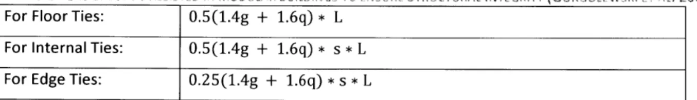
Table 3.1 Tensile Loads resisted in modular buildings to ensure Structural Integrity (Gorgoloweski et al. 2001)
... 4 5
Table 4.1 Building Drift and Maximum Module Displacment for Building Protoypes with Pinned Modular Interco nnectio ns...59 Table 4.2 Typical Modular Building Height Depending on Stabilizing System (SCI 2018) ... 61
Table 4.3 Core Thickness required to limit total building Drift to H/400 in Pin Connected Building Protoypes 64 Table 4.4 Structural Behavior of Building Prototypes with Rigid Connections... 69 Table 4.5 Stiffness Requirements of Modular Building Systems with Rigid Connections and Concrete Core ... 72
Table 4.6 Structural Behavior of Modular Protoypes with Horizontal Post-Tensioning...82 Table 4.7 Structural Behavior of Modular Protoypes with Vertical Post-Tensioning ... 82
Chapter 1. Introduction
Modular construction is a term used to describe the use of pre-fabricated building components that are assembled on site to create a complete building. Figure 1.1 shows the basic steps involved in erecting a modular building, including: manufacturing modules in a factory, delivering them to a site, and assembling them together. Because modular buildings are composed of discrete modules, they
must be connected together, using interconnections, so that the entire building behaves as a single structure. The manner in which the modules are connected together will largely impact the global structural behavior of the building. The objective of this work is to investigate different types of interconnections and their impact on the structural behavior of modular steel buildings.
1. Fabrication 2. Delivery
3. Assembly
4. Finished
FIGURE 1.1 MODULAR CONSTRUCTION PROCESS (LEE ET AL. 2014)
1.1
Motivation
The global urban population is increasing by 200,000 people per day (World Economic Forum,
2016), all of whom need a place to live and work. It would seem that in the face of such an incredible
need for new infrastructure, the construction industry would be constantly evolving to meet this demand. However, while labor productivity for industries which have existed since 1964 in the US has on average increased by 153% over the past half century, productivity in the construction industry has significantly fallen (Figure 1.2). It has been slow to adopt new innovations in technology, material use, and manufacturing processes which have greatly benefited other market sectors. The construction industry would potentially see a tremendous boost in productivity from prefabrication and
standardization. Prefabrication reduces project delivery time and construction costs by enabling more productive sequencing in the construction process. Standardizing building components reduces risk and provides a greater opportunity for reuse. Modular construction incorporates both prefabrication and standardization to produce building components in a factory setting in a fraction of the time it would take to assemble them on site.
U.S. LABOR PRODUCTIVITY
300
NON-FARM BUSINESS LABOR PRODUCTIVITY 250
+153%/
200 150 100-19%
50CONSTRUCTION LABOR PRODUCTIVITY
Modular buildings provide economic and sustainability benefits over traditionally built buildings such as reduced construction costs and less material waste (described in detail in section 1.1.2). Off-site construction also creates the opportunity for buildings to be assembled faster and with less disturbance to the surrounding neighborhood. According to the Modular Building Institute (MBI), as of 2018
modular construction composed only 3.5% of the construction industry in the United States. However, this represents a 50% increase from 2014 where modular construction represented only 2.3% of the
permanent construction market share. The Sage Policy group, (a consulting firm which works with the MBI), estimates that modular construction could account for 10% of the construction market share in the United Stated by as soon as 2040. This percent increase in market share represents a change of more than 10 Billion dollars per year of new construction where buildings will be designed and engineered to be constructed modularly instead of using traditional on-site construction practices. Currently, few engineers and architects in the US have designed a modular building and there is a lack of detailed case studies which investigate the structural performance of modular buildings. As the market share of modular buildings grows, it is anticipated there will be an increased need for engineers to understand the behavior of modular buildings so as to optimize their design and engineer more efficient structures.
1.1.1 Defining Modular Construction
In this thesis the term "modular" is used to refer to buildings assembled with three-dimensional or volumetric units (Figure 1.3). However, there are many types of prefabricated construction
processes; Table 1.1, from (Gibb., A.G.F Off-site Fabrication - Pre-Assembly, Pre-Fabrication, and Modularization report 1999), illustrates various levels of off-site construction methodologies. Level 0 corresponds to a traditionally built buildings where only the material, such as the steel beams or
concrete masonry units, are manufactured offsite. Level 1 represents buildings systems that incorporate components such as pre-cast concrete slabs or prefabricated trusses. Level 4 corresponds to buildings built completely from modular units where around 60-70% of the building manufacturing is completed off site (Gibb 1999). These levels of off-site construction practices are not fixed and there are many buildings which were constructed with a process that fits somewhere in between two levels; however,
they show a clear distinction between modular buildings and those using other prefabricated
methodologies. This study examines only fully prefabricated building systems (level 4), composed of three-dimensional modules, similar to the one depicted in Figure 1.3.
FIGURE 1.3 -INSTALLATION OF A MODULAR HOSPITAL (S I EELCONSI RUCTION.INFO)
TABLE 1.1 LEVELS OF OFF-SITE CONSTRUCTION
Level Components Description of technology
0 Materials Basic materials for site-intensive construction, e.g.. concrete, brickwork
I Components Manufactured components that are used as part of site-intensive building processes 2 Elemental or planar systems Linear or 2D components in the form of assemblies of structural frames and wall panels 3 Volumetric systems 3D components in the form of modules used to create major parts of buildings, which may be
combined with elemental systems
4 Complete building systems Complete building systems. which comprise modular components. and are essentially fully finished before delivery to the site
Source: Adapted from Gibb.,A.G.E. Off-site Fabriation-PreAssenbly, Pre-Fabriation, and ModularisationWhittles Publishing Services, Dunbeath, Scodand. 1999.
1.1.2 Advantages & Disadvantages of Modular Construction
The key advantages a modularly built building has over a traditionally built one can be defined in terms of time, cost, and quality. These advantages cannot be summarized in one set of quantitative charts because of the vast variability between different construction sectors. Modular systems have the greatest competitive advantage over site-based construction in buildings where there is a high degree of repeatability. Hotels and student residences are therefore two sectors where modular systems are most widely used; the repetitiveness of rooms requires less unique modules to be designed which in term
translates to increases in construction speed and cost savings. Modular systems are used much less in office and mixed-use buildings because of the open floor plan and wider column spacing that is desired in these sectors. Table 1.2, summarizes which sectors, modular and other off-site manufacturing systems are most widely used in.
OFF-SITE MANUFACTURING IN VARIOUs Cot
Levels of off-site manufacture (OSM)
2. Elemental or
NSTRUCTION SECTORS (LAWSON ET AL. 2014)
Sectors fOr which V"N~i'ut apl'amr 3. Mixed- 4. Fully
OSM is most Structural 2D construction modukar
relevant frames panels systems systems
Housing I V, Apartments- I/ V V( multistorey
Student
residences Military accommodation Hotels Office buildings V IV Retail buildings Health sector buildings Educational buildingsMixed use. e.g., retail/residential Industrial. e.g., V V single storey Sports buildings I/ V V Prisons and %/ security buildings
Note: / -v. widely used: v often used: v , sometimes used.
A major driver in many development projects is "time to operation." The faster a building is
completed, the faster it can start creating revenue for the owner. The time to operation can be
simplified into two parts: design and construction. The architectural, structural, and mechanical design of a building takes roughly the same amount of time whether on or off-site construction processes are used. However, Gibb (1999) found that the construction period of a modular building can be half of what it would be for a comparable traditionally built building. The relative speed advantage modular construction has over on-site construction comes from the ability to complete several aspects of the building at the same time. Modules may be manufactured while a building's foundation is still being
14 TABLE 1.2 USE OF
excavated. Although traditionally constructed buildings may incorporate top down construction
techniques to start building upper levels before finishing the below ground levels by leaving access holes in each basement slab to allow for excavation of lower levels, this process is only used for buildings with more than 2 sublevels. Similarly, a modular factory may manufacture several floors of a building at the same time whereas an on-site construction crew is limited to building one floor at a time.
To compare the differences in schedule and cost between traditionally built and modular buildings a case study method is often utilized. It consists of identifying projects which match target criteria and documenting quantitative and qualitative data through literature reviews, questionnaires, and interviews. However, because most development projects are unique it may be difficult to find a direct comparison between a building built using a modular process and one built using on-site construction techniques. Smith (2015) proposes an alternative method to compare the cost and
construction speed between traditionally built and modular buildings. The method consists of finding an existing building which was built using on-site construction but its layout and application made it
feasible to possibly be built modularly. The building's plans and specifications would then be put out to bid by modular building manufacturers and partnering general contractors centered in the same area where the existing building is located. The bid data may then be compared to the actual cost and schedule of the existing traditionally built building. Figures 1.4 and 1.5 depict a summary of the results found by Ryan Smith and the Modular Building Institute when comparing the cost and construction speed of similar modular and traditionally built buildings using the case study method.
MODULAR VS. SITE-BUILT: CONSTRUCTION SCHEDULE COMPARISON
0 MODULAR CONSTRUCTION APARTMENT/ CONDO i SITE-BUILT CONSTRUCTION HOSPITAL EDUCATIONFIGURE 1.4 - MODULAR VS SITE BUILT: CONSTRUCTION SCHEDULE (RYAN SMITH & MBI: PERMANENT MODULAR CONSTUCTION, 2015)
MODULAR VS. SITE-BUILT: COST PER SQUARE FOOT COMPARISON
0 MODULAR CONSTRUCTION APARTMENT/ CONDO HOSPITAL - SITE-BUILT CONSTRUCTION RETAIL EDUCATION
FIGURE 1.5 - MODULAR VS SITE BUILT: COST COMPARISON (RYAN SMITH & MBI: PERMANENT MODULAR CONSTRUCTION,
2015) 16 20 15 10 0 z z 0 STUDENT HOUSING I MIXED USE 0L 0 $450 $400 $350 $300 $250 $200 $150 $100 $50 $0 STUDENT
The controlled environment in which modules are produced allows modular buildings to be constructed more efficiently and with a higher level of quality. The advantages of modular construction over on-site construction processes may be summarized as follows:
* Less material waste - due to automation and repeatability
0 Higher quality of interior finishes - due to controlled production environment of Level 4
pre-fabricated buildings
* Shorter build times - proven by Smith (2015)
* 75% fewer safety incidents - due to controlled factory production (Smith, 2015)
0 Potential ability to dismantle and reuse the building - due to individual module structures
* Less disturbance to the surrounding neighborhood - due to factory production
A major disadvantage of modular construction is the limitation placed on the width of interior
building spaces. The maximum size of a module is usually governed by transportation restrictions but larger modules may be used if permitting is acquired and an escort service is used when the modules are transported. Most modular manufacturers in the US, manufacture modules only up to 16 ft. in width
(MBI). This limits the ability to have large open spaces which are constructed with modules. According to New Holland Pennsylvania based modular manufacturer, Niagara Relocatable Buildings (NRB),
modules may get damaged while being transported which causes installation issues. If the frame of a module is bent out of place either during transportation or installation then it may not properly align with surrounding modules. Any adjustments which have to be made to modules once they arrive on site are often very costly (NRB). Although modular buildings provide many benefits over traditionally
constructed buildings the infrastructure needed for factory production requires greater investment in fixed manufacturing facilities and construction repeatability is required to achieve an economy of scale in production.
1. L Prr-kIcm I I r ti tr
-1J K)I VI I I -)LL IZ I I I i__I I L
1.2.1 Design of Modular Buildings
Steel modular buildings present a unique set of construction and structural challenges. Most practicing architects and structural engineers in the US have little to no experience designing modular structures. However, as more development projects are incorporating modular construction, architects and engineers will need a better understanding of the design requirements and structural performance of modular buildings.
The schematic and early design development (SD and DD) phases of a project are critical to a project's success. Issues in the final design and construction of building often stem from mistakes made in these early design phases. It is therefore imperative that questions regarding the overall structural behavior of a modular building be addressed in these early design stages.
A major structural aspect which should be considered in in these early stages is the design of
modular interconnections. The overall structural response of an assembly of modular units is influenced
by the behavior of interconnections. The design of these interconnections will impact the selection of a
building's gravity and lateral force-resisting systems as well as the overall architectural layout. The selection of modular interconnections will affect a buildings drift, acceleration, and member deflection; therefore, understanding the tradeoffs between different modular structural systems can lead to a more efficient design.
1.2.2 Thesis Goals
There is a need for engineers to understand the impact different interconnections have on the structural performance of modular building in the early design phases of a project so as to reduce the amount of design iterations and engineer an efficient structure. Therefore, the goals of this thesis are:
* Investigate the tradeoffs in terms of structural performance, constructability, and cost between steel modular buildings with different interconnections.
* Investigate feasibility of building high-rise modular buildings with rigid frames acting as the main lateral force resisting system
1.2.3 Approach
The approach used in this thesis is to model several modular building prototypes using SAP2000 v18, a structural analysis and design software developed by Computers and Structures INC (CSI), which have varying interconnections and building aspect ratios. The structural performance of the modular interconnections is then investigated using the notional element removal approach detailed in section
3.1. Less quantifiable attributes of the interconnections such as constructability and cost aspects are
studied through a literature review and interviewing modular building manufacturers.
1.3
Outline of Chapters
In Chapter 2, modular construction, its various forms and applications are explored as it is still a relatively new construction. The literature review provides the context for this thesis and establishes the need for the studies conducted. The chapter also identifies the parameters and constraints which influence the design and behavior of modular buildings.
In Chapter 3 the methodology used to conduct the study and achieve the thesis goals is presented. Several published guidelines which outline approaches to study modular buildings are explained and compared.
In Chapter 4, four different interconnections are analyzed. Their use in the industry and influence on the structural behavior of modular buildings is examined. The results of the structural integrity study are presented and their implications are discussed. The different modular connections are compared and their use in modular buildings of various heights is critiqued.
In Chapter 5, the benefits and challenges of constructing high-rise modular building with various lateral force resisting systems and interconnections are explored.
Chapter
z.
iodular
use ana
uesign
2.1
Background to Modular Construction
The use of modular construction is expanding to innovative applications. The first modular structures were small and simple buildings; but today modular construction is being used in buildings that are 30+ stories tall with complex geometries and non-uniform layouts. To better understand the possible applications of modular construction, various types of prefabricated modules and their uses are outlined below.
2.2.1 Module Categorization
Modules may be manufactured out of various types of materials including: steel, concrete, and timber. This thesis focuses specifically on modular buildings made of steel, but some of the concepts and ideas may be applied to concrete and wood modular buildings as well.
Steel modules are often classified based on their structural systems as follows:
1. Four-sided modules (Figure 2.1 a)
* Four-sided modules are continuously supported on all their longitudinal sides which bear on the walls of the modules below.
* Walls, floors and ceilings, are usually composed of cold formed C section studs placed singly or in pairs
" Lateral force resistance is provided by X or K-bracing in the walls of the modules to create
diaphragm action of wall and floor panels. 2. Corner Supported Modules (Figure 2.1 b)
" Corner supported modules have open sides with columns only incorporated at their corners
and sometimes at intermediate points
* Columns are usually composed of hot rolled square HSS or angles
* Lateral force resistance is provided by rigid connections, added bracing, or external systems.
iqIii
IL(a)
(b)FIGURE 2.1 - MODULAR CATEGORIZATION. (A) FOUR-SIDED MODULE (B) CORNER SUPPORTED MODULE (LAWSON ET AL.
2014)
Four-sided modules are used primarily in buildings no taller than three stories because of their cold formed design (Lawson 2011). Corner-supported modules offer greater flexibility when designing an interior layout because of their open sides. Although Figure 2.1b depicts a module with a standard rectangular geometry, corner supported modules made be manufactured in L-shapes, have balconies cantilevering from them, or be outfitted with staircases.
2.1.2 Lateral Load Resisting systems in Modular Buildings
In traditionally built buildings, many types of lateral force resisting systems have been
incorporated including those illustrated in Figure 2.2. Lateral force resisting systems are selected based on factors such as the building' geometry, geographic location, seismic region and serviceability criteria. Wind loads increase with height and therefore lateral force resisting systems are critical to the structural
While most of the structural systems illustrated in Figure 2.2 could be theoretically applied to a modular building, so far, the vast majority of modular buildings have incorporated braced frames or concrete cores to resist lateral loads (Lawson et al. 2014). The tallest modular building constructed so far is the Atlantic Yards Tower located in New York City, (described in detail in section 2.3). The modular tower is 32 stories tall and therefore at this height such building systems as belt trusses or bundled tubes would be excessive and most likely not cost effective. X or K-bracing may be incorporated inside modular walls as illustrated in Figure 2.1a. The braces in modular buildings are often made of flat rectangular bars or angles and can be designed to resist tension and compression or tension only. The majority of modular buildings which rely on in-wall bracing as the main lateral force resisting system are no taller than 6-8 stories (Lawson et al. 2014). In conventionally constructed buildings, braced frames have been used in buildings of upwards of 40 stories (Ayman 2010); however, in modular buildings the braced frame must fit within the walls of a module and therefore the bracing is smaller than what it could potentially be in a conventionally built building.
140-130
10 R
11
40
FIGURE
2.
2- BUILDING SYSTEMS (AYMAN2010)
For modular building taller than 7 stories, concrete cores have been the predominantly used lateral force resisting systems (Lawson et al. 2014). The core is often constructed using traditional cast in place construction techniques. (Figure 2.3 a) depicts the Paragon, an 11-story residential complex located in Brentford London, UK. A self-climbing concrete formwork system was used to construct the concrete core of the Paragon which acted as the main lateral force resisting system and also housed the elevators and stair cases. A pre-cast concrete module such as the one depicted in (Figure 2.3b) may also be used to construct a buildings core. Whereas it typically takes a day to erect one stories of cast in place concrete core, more than 5 stories of a precast core can be erected in a single day. However, a precast core has to be heavily reinforced with steel at its lifting points so that it can resist the tension loads when it is being assembled into place. The precast concrete relies on frictional bearing but connection bolts are used to ensure positional accuracy between the modules. A third option for the central core is utilizing a twin wall. Twin wall construction is a combination of in situ and precast concrete construction. The twin wall, consists of two precast reinforced concrete skins which are connected and spaced with a steel lattice. The concrete skins act as a permanent form work and act compositely with the in-situ concrete which is cast between them. The twin wall system takes longer to construct than a fully precast core but the in-situ placed concrete creates a stronger connection
between the core units. "Corefast" is another type of prefabricated core, (Figure 2.3c). It is a steel composite core, similar to the twin wall except steel panels are used instead of the precast concrete panels. The steel panels confine the concrete which increases its load carrying capacity, however the exposed steel must still be fire-proofed. Steel brackets which are welded to the Corefast walls are used to connect the modules to the wall.
Concrete cores are commonly used in both concrete and steel conventionally built buildings as lateral force resisting systems because of their structural and constructability advantages. Concrete cores are often placed near the center of buildings and may be designed to take large portions of the gravity loads which in turn reduces the number of interior columns required and frees up floor space. Services system such as elevators and stairs require fire proofing which often comes in the form of concrete walls, thus the concrete core is able to serve a dual purpose. The hollow tube shape of the concrete core enables it to resist multi direction wind and seismic forces as well as any torsional loads.
I
'
Ir
I
~i rn-I (a)FIGURE 2.3 - MODULAR CORE SYSTEMS. (A) PARAGON UK, CASE IN PLACE (B) PRE-CAST (C) COREFAST SYSTEM (CALEDONIAN MODULAR, MAY 2018)
Although the vast majority of 7+ story modular buildings have been constructed with a concrete core, there are several disadvantages of having to rely on a core as the only means to provide lateral stability in a high-rise modular building. In order for a concrete core to provide lateral stability to the rest of a building, there must exist a continuous load path where seismic and wind forces can be transferred to the core. In conventional buildings, the roof and floors are integrated with the structural framing system through a concrete slab or composite deck so that they effectively act as a single diaphragm which provides a continuous load path. However, in modular buildings this lateral congruity
24
/
(b)I
I
L'
IL
JI4'
(c)is not inherent because of the discontinuous nature of modules. The majority of modules used in pre-fabricated buildings are connected only at their corners which complicates the transfer of lateral loads to the core (Sharafi et al. 2017). Often extra reinforcing in the form of in-plane trusses must be
incorporated in the corridors to assist in transferring these loads (Lawson et al. 2014). In some instances, an in-situ concrete floor slab is poured after the modules on a particular floor have been assembled to create a continuous diaphragm which connects to the concrete core. However, this practice reduces benefits such as construction speed and reduction of construction waste that a fully modular building provides to the end user (Gunawardena 2016). An in-situ poured concrete slab also inhibits the ability to reuse or relocate the modules.
In many conventional buildings with concrete cores, the concrete core is designed to resist both lateral and significant gravity loads. As depicted in the floor framing plan shown in Figure 2.4, beams often span directly between perimeter columns to the concrete core forcing the core to support a large tributary area. In traditionally constructed buildings this beam layout reduces the number of interior columns and creates a more open interior space. However, as depicted in Figure 2.5 modular buildings are designed so that gravity loads are transferred directly from module to module and therefore do not rely on the concrete core to carry much of the gravity loads. Modules must be supported at all four corners in order to be lifted by a crane and installed without deforming, therefore, creating an open floor plan with much of the gravity loads resisted by the concrete core as shown in Figure 2.4 would not be feasible.
In both conventional and modular buildings, concrete cores are often placed in the center of the building. As shown by Figure 2.6 the torsional displacements a building experiences are minimized when the eccentricity between the center of mass of a building and the center of rigidity is reduced. However, because service areas are often located inside the central concrete shear core this creates a restriction on where stairs and elevators may be placed. This restriction limits the freedom architects have in designing a buildings floor plan.
Because of the disadvantages present in using a concrete shear core as the main lateral force resisting system of a modular high-rise building it is worth exploring other potential structural systems.
"N, 12m
>1
1~
17-'1~
I.' VA
FIUR 2. - TYIAIEMLYU AON OCEECR
I
ELCNTUCIN II I
12
FIGURE 2.5- GRAVITY LOAD TRANSFER IN CORNER SUPPORTED MODULAR BUILDING (SHARAFI ET AL., 2017) Large Displacement A I Seismic Force
I
i
-~ $ 9I.
I
Center of+Mass
U
Stiffness Small DispilacementI
p
IIa
I I I UFIGURE 2.6 - STORY ECCENTRICITY (MIDASUSER, MAY 2018)
26
-f
K.2
M Ad ilar I
nter
-nnectifns
Connections between modules have a significant influence on the structural stability of a modular building. Modular interconnections are made at the top and bottom of modules so that adjacent modules are connected at their corners. Steel module floor systems are often comprised of a
metal deck which is supported on purlins made of hot rolled rectangular HSS sections or cold formed channels. The subfloor is then constructed using cementitious particle boards followed by acoustic padded and floor finishes. In this floor system no concrete is used making the modules relatively light. On average steel modular systems without concrete slabs weight approximately 65% of a conventional RC flat-slab building (Farnsworth, 2014). However, without a cast in place concrete slab the modules are structurally unattached to each other. Interconnections are required to provide a continuous load path. Lateral loads are transferred between the individual modular diaphragms through the interconnections, until they reach the lateral force resisting system. Interconnections need to be designed to transfer horizontal forces due to wind, earthquakes, and extreme or accidental loads. Interconnections are also designed to provide alternative load paths in the event of accidental damage to structural members. Sections 2.2.1 and 3.1 describe in more detail how modular interconnections are critical in providing structural integrity in modular buildings and preventing progressive collapse.
Mechanical fasteners, such as those shown in Figure 2.7, are the most common type of modular interconnection. They are usually comprised of an arrangement of horizontal and vertical plates that are bolted or welded to the external face of modules. To realize the advantage of using pre-fabricated modules with finished interiors, all structural connections should be made external to a module. The modular interconnections are usually installed using external scaffolding and other mobile access platforms (Lawson et al. 2014). Although alternate proposals of attaching modules such as through interlocking or post tensioning are being explored, mechanical fasteners located on module corners are the most popular connecting systems due to their simplicity, they do not require a highly skilled
workforce and ease or service. As illustrated in Figure 2.7 many of these mechanical fasteners can be constructed with only a single steel plate and two bolts. However, the design of these simple
connections makes them uncapable of transferring significant moments between modules. They are often modelled as simple pin connections that transfer only shear and axial forces.
-ItJ
HI7
100 x 100 x 10 Bolted Connection PLAN Top Mod e ---0 Roof Sectior 0 x 100x 100x 101L Connector P1 to 4 0 ELEVATION a a I I a I j a a I * a a a * a a a a a a I a I Locator L a) ~:-~ Plates a, I a, 'I4!
Lifting Plater-4I~~7maaa~ Shear Key
a ha a a a g p g a I a p Top Module --.. - - -. Lower Module * a * a * a * a * a * a * a a a * a * a * *Ill',' I a a a A4~ Locator Plates "*NLifting Plate Sheer Key
FIGURE 2.7 - TYPES OF MODULAR CONNECTIONS (MILLS ET AL. 2015)
28
---Lower Module
2.2.1 InterInrnn NAng lar Systems
In the majority of modular buildings, modules are designed to connect to each at their corners through mechanical fasteners to ensure vertical stability of the structure. However, several researchers have proposed novel ways to interlock modules without the use of interconnections; they are worth exploring because of the disadvantages inherent in mechanical fasteners and the potential
constructability and structural benefits that these innovative interconnections may bring.
In his paper "Interlocking system for enhancing the integrity of multi-story modular buildings", Sharafi et al. (2017) introduce an innovative way to interconnect modules called the "modular
integrating system" or (MIS). The system is comprised of a pair of interlocking joints (Figure 2.8) which fit on each of the six edge beams of every module. The topological interlocking system consists of rigid integral mechanical attachments defined as "connection type A" and "connection type B" in Figure 2.8. Both connection types are composed of tongues and grooves that when attached will interlock two or more modules and prevent relative motion in major directions of translation and rotation and prevent unwanted separation, (Sharafi et al., 2017). The only difference between connection type A and B is that the interlocking strips have opposite tongue and groove patterns. Incorporating only two different types of connections and significantly simply the design and construction of a building. A traditionally built steel building will often have several different connections due to range of different beam and column sizes. Similarly, modular buildings which are connected with mechanical fasteners may require different interconnections for joints which connect different groups of modules.
In the modular integrating system, two adjacent modules are connected by simply using a crane to push one of them in the direction perpendicular to the length of the tongues and grooves. In order for the modules to become properly interlocked a specific assembly method must be followed. The corner module on the base level is placed first, then adjacent modules in the first row and column of the module layout plan are assembled using a simple push slide motion. This is repeated until the last module on the opposite corner is placed and then the same order is followed on each upper level. This assembly method will cause all adjacent modules to be integrated and for the whole system to be
through the diaphragm and their collector elements until they reach the lateral force resisting system of the building. Modular buildings with mechanical fasteners at the corners of the modules rely on the fasteners to transfer loads between the diaphragms of each module. The failure of a single fasteners will cause a discontinuity in the load path and may cause stress concentrations in the other fasteners (Lawson et al. 2014). However, the modular integrating system allows for adjacent modules to be connected at several locations so that the failure of any individual tongue to grove connection has a minimal impact on the structural integrity of the building.
(a)
verfA all(b)
Connection type A
Connection type B
(c)
FIGURE 2.8 - (A) ATTACHMENT OF INTEGRATING CONNECTION TYPES. (B) ATTACHING TWO ADJACENT MODULES. (C)
INTERLOCKING STRIPS (SHARAFI ET AL. 2017)
The integrating connection transfers loads between modules by having the tongues and groves bear on each other. The mechanical interface resists shear and compressive stresses that are
30
imposed from external loads which try to displace the modules Figure 2.9. Moments can be resisted by the modules because the interlocking tongues and grooves resist overturning. Moment connections in traditionally built steel buildings Are often difficult and costly to construct because of the large amount of on-site labor required to make a rigid connection between two steel frame members. The integrating design allows for modules to act as rigid frames and be assembled in a manner where it easy to visually see if connections were properly constructed. However, a disadvantage of the interlocking connection is that it does not resist tension in the direction opposite of the applied load. The modular integrating system is also limited to modular buildings which consist only of rectangular modules which are the same size. It would be difficult to integrate the system into a building with more complex geometries.
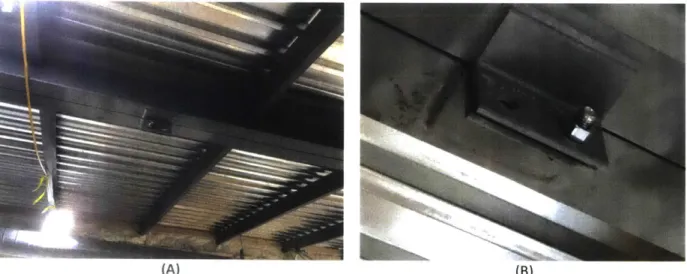
One of the main advantages of the modular integrating system is that it provides a more redundant interconnecting system than linking modules only at their corners using mechanical fasteners. Adjacent modules may also be connected by incorporating intermediate mechanical connections such as those shown in Figure 2.10. The intermediate mechanical fastener consists of angles which are welded along the outside perimeter of the modular ceiling edge beams. When the modules are assembled on site the angles of adjacent modules are then bolted together as depicted in Figure 2.10b; several of these connections may be incorporated along the edge beams of each module. These intermediate fasteners would add a level of redundancy to a modular building so that if a corner connection between two adjacent modules failed, the intermediate fastener would still apply a tying force between the two modules. Adjacent modules tend to slip with respect to each other when subject to lateral loads because of the discontinuity between modules (Lawson, 2005). These intermediate fasteners would help to resist the horizontal shear forces caused by lateral loads and limit non-uniform displacements between modules.
(a) (b) (c)
(B)
FIGURE 2.10- INTERMEDIATE MODULAR FASTENER. (A) CONNECTION LOCATION (B) INTERMEDIATE BOLTED CONNECTION (IMAGEs TAKEN BY THE AUTHOR)
2.2
Applications of Prefabricated Modular Structures
Prefabricated construction has been used for several centuries in Europe and Japan. One of the earliest accounts is that of John Rollo, a Scottish military surgeon, who described the use of portable hospital buildings in the West Indies in the 18th century. From then on, modular construction has been
used in new and innovative applications.
2.2.1 The London Crystal Palace
One of the earliest and most iconic examples of prefabricated construction is the London Crystal Palace seen in Figure 2.11. In Europe it opened the way to the Modern Movement and influenced the use of new construction materials and methods in the US. The London Crystal Palace was designed by Sir Joseph Paxton for the Great Exhibition of 1851. The "Great Exhibition of the Works of Industry of all Nations" showcased the latest technologies and innovations from around the world and so it was imperative the building itself was an engineering marvel.
Paxton, who before designing the London Palace, was a famous gardener, was influenced by his passion for biomimicry (the design of structures and systems that are modeled on biological processes). His previous work included designing the public gardens at Bikenhead Park which directly influenced the
design of Central Park in New York City. He was particularly inspired by the giant leaves of the Victoria Amazonica waterlily (Figure 2.11b) and attempted to mimic its compact design (Merin 2013).
The design of the London Crystal Palace consisted of large open spaces supported by cast iron columns, trusses and x-braces which supported a completely glass fagade (Figure 2.11c). However,
rather than design the Palace to be constructed beam by beam, Paxton implemented a modular approach by creating a system of right angled triangles which held 10in x 49in glass panels and were supported by a grid or mirrored cast iron beams and pillars. The modular glass components were prefabricated and installed at a rate of 18,000 panes a week allowing the project to be constructed in 5 months. (a) (b) a ulldings.
kX
dlLu 1
131
Paxton combined together tested building designs, materials, and construction methods from various manufacturing, engineering, and construction fields in order to construct the building in record time. Paxton standardized several elements of the Crystal Palace's structural system such as the cast
iron columns. All ground floor columns were 22 ft. long and those above were 20 ft. long. In order reduce the number of different connections, the external dimensions were kept constant for the majority of columns and girders (Addis 2006). The wall thicknesses of the columns and girders varied based on the applied loads but their cross-section widths and depths remained constant. A fixed connection was created between the cast iron columns and girders using a series of wedges (Figure 2.12) Both cast iron and oak connections were used. The oak allowed for greater longitudinal movement as the Crystal Palace expanded and contracted with changes in temperature.
The roof of the Crystal Palace was supported on the "Paxton Gutter." During its construction, the Paxton Gutter was a novel system which carried both rainwater and condensation from the interior surface of the glass along separate channels into the top of the hollow columns (Addis 2006). Paxton limited the deflection of the gutters and reduced ponding by pre-cambering the gutters with adjustable trussing rods. The hollow columns which doubled as drain pipes were incorporated in sections where the roof of the Crystal Palace was flat and water could not runoff naturally. The columns were
connected at their bases to horizontal pipes using molten led, which then led to the main sewer system at the south of the building.
The lateral force resisting system of the Crystal Palace was comprised of both Vierendeel trusses and diagonal braces. The Vierendeel action was provided by the rigidity of the column to girder
connections created by hammering in cast iron wedges. The Vierendeel system was rare at the time and Paxton explained how it worked by comparing it to a rigidly connected wooden table (Addis 2006). Diagonal braces were fitted in 220 vertical bays to keep the cast iron beams and columns from carrying excessive bending stresses. The timber floors of the Crystal Palace acted as part of the diaphragm carrying wind loads from the glass facades, to the diagonal braces and fixed frames, and down to the concrete foundation.
Structural pre-assembly was a major reason the Crystal Palace was erected in just 27 weeks. Rather than receive prefabricated components from a modular factory, as is done today, mini
manufacturing workshops were set up around the palace. Six horse-power steam engines were used in the workshops which provided power to drive the machinery for routing, shaping, sawing, and drilling the structural components. The rigid connections allowed for the frames to be assembled with
minimum temporary supports. The timber ribs which made up the arches of the transept vault were too
slender to lift into position individually without deforming. Several timber ribs, purlins, and wrought iron diagonal bracing were preassembled on the ground floor and lifted as a single unit which prevented any of individual pieces from breaking and decreased the construction time.
L
*\ /0
N ~ A.7
p
7
1~t
(A) (B)FIGURE 2.12 -CRYSTAL PALACE COLUMN TO GIRDER CONNECTION. (A) CONNECTION SECTION VIEW (B) CONNECTION
INSTALLATION (ADDis, 2006)
2.1.2 Victoria Hall, London UK
Victoria Hall is a modular built student dormitory located in Northern London. The 19 Story building, shown in Figure 2.3, is comprised of 435 student rooms spread among 3 wings which surround
West Sussex and then transported them 90 miles to Wembley where they were assembled by the general contractor Mace.
The wings of Victoria Hall are composed of modules which are 52' long x up to 12.5' wide. This module size makes it possible to incorporate a twin corridor and two rooms, reducing the amount of on -site work required. The corridors are finished after modules are installed and provide access for
services to be connected. Each wing of Victoria Hall consists of 10 modules per floor and 3-4 floors were installed per week. It is estimated that the student dormitory was completed 6 months faster than it would take it build it using only on-site construction (MBI). The fagade of the buildings consists of light weight rain screen cladding supported on horizontal rails attached to the modules. The modules are weather tight, and fully insulated. The use of modular construction allowed Victoria Hall to be constructed much more sustainably than a traditionally built building.
e
r
FIGURE 2.13 - VICTORIA HALL, UK (FUTURE FORM 2011)
The main lateral force resisting system implemented in Victoria Hall is a concrete core. While the wings are made of steel frame modules, the central tower was built on site using cast in place concrete. Figures 2.4 and 2.5 shows the core being cast in place using self-climbing concrete formwork system while the at the same time modules are being installed in the three wings. The walls and floors of the modules are constructed by welding together cold formed steel C-sections. Although the modules themselves are composed of rigid connections, because the building height is over 200 feet,
the overall structure would not be able to resist the high wind loads without the support of the core. The majority of modular buildings over 6 stories rely on a core for lateral stability (Lawson et al. 2014). The modules themselves make up the individual rooms and carry the majority of the gravity loads. The
central core houses elevators, stairs and service risers, it increases the rigidity of the building and limits drifts and displacements due to wind. In order for the modules to properly engage the core, additional bracing had to be incorporated within the module floors and ceilings. Lateral forces were transferred between modules through the modular interconnections. Ensuring the modules are properly braced to the core creates structural and construction challenges. The concrete core is subject to creep and shrinkage, while the steel modules experience little long-term deformation. A maximum manufacturing deviation of 0.2 inches was achieved between adjacent modules. Construction tolerances for the concrete core were much greater which could cause out of verticality in the modules. The interior spaces within the core are built on site which reduces the benefits in sustainability and quality control that a fully modular building would experience.
2.1.3 Atlantic Yards, New York
Atlantic Yards B2 Modular Residential Tower, (referred to from now on as Atlantic Yards) is the tallest modular building in the world. At 32 stories, (Figure 2.61), the tower, which was finished in 2016, is by far the most ambitious modular building constructed in the United States. Compared with
countries like the United Kingdom, Japan and South Korea where modular construction has been used much more widely, the US has lagged behind in adopting modular construction, with only 3.5% of new development projects being built with modular construction (MBI, 2018).
Located and manufactured in Brooklyn, New York, the tower was designed by SHoP and Arup for the developer Forest City Ratner. The tallest modular building before Atlantic Yards was a 24-story apartment tower in Wolverhampton, UK; the design team for Atlantic Yards was tasked was developing a modular system which was optimized for construction market conditions in NYC and could be
delivered at a price competitive with conventional flat-slab construction. Figure 2.17 shows the modular floor plan which consists of 36 modules per floor; a 90 ft. transfer girder, (Figure 2.19), is used over the entrance of the Barclays Center to support 19 stories of modules above. The substructure was built conventionally with steel floor framing and reinforced concrete perimeter walls.
ij
--4i
FIGURE 2.16 -ATLANTIC YARDS (SHoP ARCHITECTS) FIGURE 2.17 - MODULE LAYOUT (FARNSWORTH 2014)
The module sizes were governed by transportation restrictions, with the largest modules being
50 ft long, 15 ft wide and 10.5 ft tall. The module sizes were also influenced by crane requirements; the
heaviest modules were designed to be close to the 26-ton tower crane to fall within the lift limits at different crane radii. Atlantic Yards had 225 unique module structure types. Incorporating such a large variety of modules is uncommon because modular construction is most cost efficient when
standardization in manufacturing is achieved. However, Forest City Ratner desired to have a wider range of apartment types and chose mass customization over mass production (Farnsworth 2014).
The modules are stacked on a conventional steel-framed plinth level above the ground floor which makes it possible to have open areas, unencumbered by module walls in the lobby and provides a level platform to stack the modules on. Figure 2.8 depicts the structural components of a single module. The fully welded steel-framed chassis is comprised of 6" square HSS corner columns, 8" by 4"
rectangular HSS bottom chords and 2" by 3" intermediate posts. The module floor system consists of a 2" metal deck running in the long direction of the module, supported by 6" by 3" rectangular HSS
included as diagonal bracing to minimize module weight and deflections. The sides of modules without steel bracing act as welded Vierendeel trusses spanning between corner columns.
Roof Purka
Roof Deking
Roof C hords
Strap Bracusg
Posts
Floor Chord F r Parla
C oruor Columas r Deckin
FIGURE 2.18- MODULE STRUCTURE (FARNSWORTH 2014)
Hat Truss
Building Setbacks
E-W Braced Frames
E-W# V
N-S Braced Frames
Dean Street Transfer Building Massing
Typical Modules
r4 19 Plmth
Basement and Foundation
FIGURE 2.19 - ATLANTIc YARDS STRUCTURAL SYSTEM (FARNSWORTH 2014)
The lateral force resisting system consisted of conventionally built steel braced frames. Two inverted v-braced frames were constructed in each primary direction and tied together at the roof level with a hat truss (Figure 2.9). Lateral loads were transferred to the braced frames from the roofs of the
modules which were composed of 1" metal decks and supported by 3" rectangular HSS purlins and acted as the lateral diaphragm. The module roofs were designed to act as the lateral diaphragms instead of the module floors to minimize the potential for on-site activities to damage the finished apartments (Farnsworth 2014). Although modular interconnections were incorporated between the module roofs, they were designed to transfer the full lateral loads to the braced frames (Figure 2.10). The modules were designed to carry only gravity loads. The interconnections were designed as an assembly of thin steel tension plates to resist against progressive collapse.
Atlantic Yards deviates from the majority of high-rise modular buildings in that it does not use a reinforced concrete core as the main lateral force resisting system. A central core was considered but was ultimately abandoned to minimize the number of union trades on site. A steel only solution reduces construction tolerances between systems and makes it simpler to transfer lateral loads from the module diaphragms to the braced frame. Connection issues between the modules and lateral force resisting system are reduced in the steel-only option because the creep and shrinkage of a reinforced concrete core do not have to be considered. The stairwells and elevator core were constructed modularly and did not have to be confined to being placed in a central concrete core.
Although Atlantic Yards stands as the tallest modular building in the world, while it was being constructed it was faced a myriad of issues that caused Forest City to part ways with its modular division. The tower ended up taking twice as long as scheduled to construct at a cost far more than
projected. Half of the first 39 units suffered water damage and the interior finishes had to be replaced. Several steel chassis were damaged during transportation which caused the modules to be misaligned when installed. Forest City partnered with Skanska in manufacturing the modules at their plant in Brooklyn's Navy Yard. However, disputes over the scope of work broke out between the two firms causing Skanska to temporarily close down the factory and eventually withdraw from the partnership. Skanska CEO, Richard Kennedy, claimed that misalignment issues were created because of the limited adjustability of the conventionally built steel frames. The plethora of issues associated with the construction and design of the Atlantic Yards tower prove that although modular construction has the possibility of revolutionizing the construction industry, more research and scientific studies are required to successfully implement modular construction practices in high-rise buildings.
I
af
FIGURE 2.20 -ATLANTIC YARDS CONVENTIONALLY BUILT BRACED FRAMES (FIELD CONDITION 2014)