HAL Id: hal-03058399
https://hal.archives-ouvertes.fr/hal-03058399
Submitted on 18 Dec 2020HAL is a multi-disciplinary open access archive for the deposit and dissemination of sci-entific research documents, whether they are pub-lished or not. The documents may come from teaching and research institutions in France or abroad, or from public or private research centers.
L’archive ouverte pluridisciplinaire HAL, est destinée au dépôt et à la diffusion de documents scientifiques de niveau recherche, publiés ou non, émanant des établissements d’enseignement et de recherche français ou étrangers, des laboratoires publics ou privés.
Challenges in the Certification of Computer
Vision-Based Systems
Frédéric Boniol, Adrien Chan-Hon-Tong, Alexandre Eudes, Stéphane Herbin,
Guy Le Besnerais, Claire Pagetti, Martial Sanfourche
To cite this version:
Frédéric Boniol, Adrien Chan-Hon-Tong, Alexandre Eudes, Stéphane Herbin, Guy Le Besnerais, et al.. Challenges in the Certification of Computer Vision-Based Systems. Aerospace Lab, Alain Appriou, 2020, �10.12762/2020.AL15-06�. �hal-03058399�
Artificial Intelligence and Decision Making
Challenges in the Certification
of Computer Vision-Based
Systems for Civil Aeronautics
C
omputer vision techniques have made considerable progress in recent years.
This advance now makes possible the practical use of computer vision in civil
drones or aircraft, replacing human pilots. The question that naturally arises is
then to provide a way to certify those types of systems at a given level of safety.
The aim of the article is, firstly, to understand the gap between today’s computer
vision systems and the current certification standards; secondly, to identify the
key activities that must be fulfilled in order to make computer-vision systems
certifiable and, thirdly, to explore some recent works related to these key activities.
F. Boniol, A. Chan-Hon-Tong, A. Eudes, S. Herbin, G. Le Besnerais, C. Pagetti, M. Sanfourche (ONERA) E-mail: [email protected] DOI: 10.12762/2020.AL15-06
Introduction
Computer vision techniques have made considerable progress in recent years. One of the most recent successes in computer vision has been achieved through the development of Deep Learning meth-ods. It seems unlikely that this trend will backtrack radically on short notice: most signal and data analysis approaches will now include somewhere in their processing pipeline one or several components that have been designed using machine learning techniques. Before the advent of Deep Learning, more conventional methods based on geometric vision already offered very interesting performances for autonomous localization.
The performance gain obtained by these techniques now makes pos-sible the practical use of computer vision in complex systems, and particularly in surface vehicles and in civil drones or aircraft, replac-ing human pilots.
Driving Automation Systems for On-Road Motor Vehicles have been widely studied. A dedicated standard [80] has been published by SAE to propose a set of recommended practices and a taxonomy describing the full range of levels of driving automation in on-road motor vehicles. The concerns and risks associated with on-road autonomous vehicles are also discussed in [94]. To address these risks, the authors explore vari-ous strategies that can be adopted and emerging responses by govern-ments. They show that, thus far, authorities have generally avoided bind-ing measures and have focused on creatbind-ing councils and work groups, in order to not slow down the development of autonomous vehicles. In this article, we focus on the civil aeronautics domain. In this domain, the strategy is quite different. An aircraft (autonomous or not) cannot enter service without being certified from a safety point of view. One of
of the (human or artificial) pilot to detect any abnormal situation or any risk of collision and to ultimately take control of the vehicle.
The issue that naturally arises for allowing the use of computer vision in civil aeronautical vehicles is to provide a way to certify a given level of safety. This is a difficult issue for such processes, which are effec-tive in their empirical domain of expertise, but it is often not possible to state why they are so.
What is a computer vision based system?
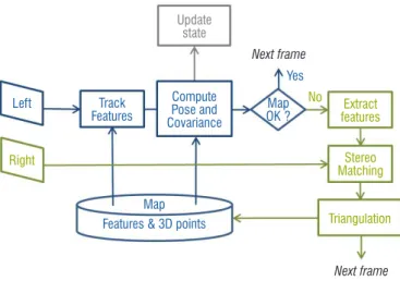
Let us begin by illustrating what a computer vision-based system is. As an example, let us consider a vision-based navigation system rep-resentative of embedded systems in robotics, drones, autonomous cars, or automated taxiway driving for an aircraft. A simplified generic architecture is sketched in Fig. 1. Visual information stems from two cameras (denoted as left and right camera) mounted together on a stereoscopic rig.
Right
Camera OdometerVisual
Other Sensors (e.g. IMU, GPS) Absolute Localization GIS Scene Interpretation Left Camera
The Visual Odometer (VO) component exploits sequences of stereo-scopic images to estimate the trajectory (position and orientation) with respect to some relative reference coordinate system.
The Scene Interpretation (SI) component uses frames from the left camera to build a description of the scene pertaining to the navigation task at hand. For instance, SI has been designed to provide bounding boxes (BB) around objects of interest, which are essentially of two types:
• Landmarks: objects referenced in a local GIS (Geographic infor-mation system) of the area;
• Obstacles.
SI should also be able to more precisely characterize detected objects of each type; for instance, providing an identification of landmarks (e.g., a traffic sign and its meaning, a ground sign and its class, etc.); and providing a category for each obstacle (e.g., moving/static object, person/car/truck, etc.).
The Absolute Localization box combines information from all other components to estimate the position/orientation of the mobile in an absolute world coordinate frame, such as WGS 84 (World Geodetic System 1984). The basic operation here is to match objects extracted by SI to landmarks in the GIS, so as to change and/or refine the esti-mated trajectory. Matching landmarks is aided by characteristics provided by SI and by the approximate 3D localization deduced from VO information. We will not enter into further details regarding the Absolute Localization component.
In this paper, we will focus on the two functions VO and SI. For both of these we will identify the gap between the current standards and their specifics. Indeed, if such a vision-based system is to be embed-ded into some operational system, these two components would have to be compliant with some certification framework, depending on the application field. The choice of these two functions is motivated by the fact that they represent two major trends in current vision resources. VO belongs to geometric vision, which is aimed at extracting geometric information from images, a field that has been theorized for instance in [41]. Although very different in their implementation details, many such geometric codes are used nowadays in robotic systems. SI is representative of the numerous recent codes for image-based scene understanding driven by machine learning techniques. Moreover, as said before, their combination opens the way to realistic vision-based systems.
Problem
The article focuses on the civil aeronautics domain. In this domain, an aircraft is allowed to enter in operation if the manufacturer has obtained a type certificate from the certification authorities. For that, the aircraft manufacturer must demonstrate the compliance of its product with the regulatory requirements [25]. An accepted means of compliance with the requirements is to rely on mature standards, such as the ARP 4754A [79] for the system’s development process, or such as the DO 178C [75] for the software development process. When using these means to prove that a product is trustworthy, the certification activities consist in providing a detailed documenta-tion, and justifications, that argue how the development process is indeed compliant with the standard.
The certification activities must cover all of the levels of the develop-ment process. In the embedded field, the developdevelop-ment process is usually divided into four levels:
• function: specification of the expected behavior, the usage do-main, and the constraints of an avionic function;
• algorithm: i.e., the methods, the structure, the algorithmic prin-ciples, etc., used to fulfil the avionic function;
• source code: i.e., the software modules, which are compiled and transformed into executable object code;
• item: i.e., all of the low level components, whether they are hardware (e.g., processors, cameras, etc.) or software (e.g., middleware, kernel devices, etc.).
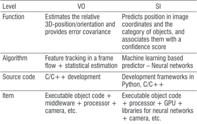
For instance, Table 1 illustrates these four levels for the VO and SI functions.
Level VO SI
Function Estimates the relative 3D-position/orientation and provides error covariance
Predicts position in image coordinates and the category of objects, and associates them with a confidence score Algorithm Feature tracking in a frame
flow + statistical estimation Machine learning based predictor – Neural networks Source code C/C++ development Development frameworks in
Python, C/C++ Item Executable object code +
middleware + processor + camera, etc.
Executable object code + processor + GPU + libraries for neural networks + camera, etc.
Table 1 – VO and SI implementation
Existing certification approaches for avionic functions, as shown in Section "Certification practice for civil avionic systems", require strong relationships between levels (such as conformity and trace-ability) and strong properties (such as determinism). However, as discussed in Section "Certification practice for civil avionic systems", some of these properties are often not shared by vision systems. For instance, VO uses optimizer algorithms to compute the best position, and optimization partly relies on the random operation of outlier rejec-tion (RANSAC, Random Sample Consensus, [29]). Similarly, SI is typically based on machine learning techniques applied to deep neural networks (DNN) [33]. In this case, it becomes difficult to ensure the traceability between each line of source code and the functional level. Another difficulty arises from the notion of failure. In safety terminol-ogy, random failure refers to item failures only, and systematic failure refers to software bugs. However, even in the absence of item and software failure, the perception functions may behave abnormally due to "bad" external conditions (e.g., bad weather conditions) or "bad" internal choices (e.g., bad random operation). The difficulty arises from the fact that these "bad" conditions partly depend on the internal algorithms, making the safety analysis more difficult.
As a result, most of today’s computer vision systems do not meet the current certification standards for civil aeronautical vehicles, although the evolution of technology makes it possible to integrate such per-ception systems into drones or aircraft.
Objectives and organization of the article
Following this observation, the objectives of the article are:
• First, to understand the gap between today’s computer-vision systems and the current certification standards;
• Second, to identify the key activities to be fulfilled to make com-puter-vision systems more certifiable;
• And last, to explore some recent works related to these key activities.
The paper is organized as follows:
• The current certification practices in the civil aeronautical field are presented in Section "Certification practice for civil avionic systems". More particularly, we discuss two certification stan-dards: the ARP-4754A [79] dedicated to safety issues (see Section "Safety design process"), and the DO-178BC [75] dedicated to software issues (see Section "Algorithm and soft-ware development process"). They are discussed with respect to computer-vision systems and we show that they are rather inappropriate for this type of systems. We also discuss in Sec-tion "Computer vision based system development process: a data driven design logic" one of the novelties of computer vision ("novelties" with respect to conventional certified systems); that is, its data driven nature: the behavior of the systems is mainly defined or tested via a great number of data (called dataset). • Section "Developing specific certification objectives for
com-puter-vision algorithms" then discusses a new certification approach (proposed by the Overarching Properties working group, and proposes 5 certification objectives dedicated to computer vision.
• Section "Visual odometry" (resp. 5) discusses the certification issues in the specific case of the VO function (resp. SI). • Finally, Section "Conclusion and challenges" proposes a list
of key scientific challenges to be explored to make the vision-based perception systems certifiable.
Certification practice for civil avionic systems
The two main certification standards that are concerned with civil avionic systems are: first, the ARP-4754A [79], which is a guideline for development processes under certification, with an emphasis on safety issues; and second, the DO-178BC [75], which provides guid-ance for developing software under certification.
Given that they are central in civil aeronautics, we briefly present these two standards in the two following subsections (ARP-4754A in Subsection "Safety design process", and DO-178C in Subsection "Algorithm and software development process") and we discuss their limitations with respect to computer-vision systems.
Safety design process
ARP-4754A design process
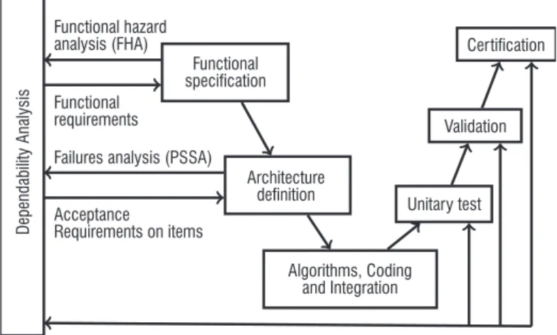
A safety critical development process is the imbrication of a usual development process (that ensures the functional correctness) with a safety assessment process (that ensures the safety requirements compliance). Figure 2 provides a schematic overview of the develop-ment process for a safety critical system compliant with ARP 4754A.
The high-level functions define the main functionality expected from the system and are analyzed with regard to the risks that they may encounter through the FHA (Functional Hazard Analysis). For each risk, the experts must identify its causes and evaluate the severity of the consequences in dangerous situations. For instance, if a failure of a function could lead to a crash, it is classified as "catastrophic"; the function will not be lost with a probability lower than 10–9 / FH, and
nothing less than a triple failure will lead to the loss of the function. If the failure of the function "only" causes serious or fatal injuries among the passengers, or could lead to physical distress of the crew, then the function is classified as "hazardous"; the probability of losing it will be lower than 10–7 / FH and only a double failure will lead to such
a loss.
After such a risk analysis, the high-level functions are then refined as a preliminary functional architecture (second step of the devel-opment cycle in Figure 2). Each high-level function is implemented as a set of sub-functions providing the expected functionality. This architecture is analyzed through the PSSA (Preliminary System Safety Assessment) to check whether the requirements from the FHA can be fulfilled assuming some properties (such as independence, failure modes and propagation rules). This step is an iterative activity: if the functional architecture does not fit the requirements, the designers must propose a new architecture with additional redundancies. Once a consolidated architecture has been found (at the end of the second step in Figure 2), the next phase is the selection of the hard-ware item, the allocation of levels of softhard-ware criticality (called DAL for Dependability Assurance Levels) to each software function, and the coding of the functions and the platform services (third step). Five Dependability Assurance Levels are defined by the certification standards (by the DO178B), from DAL A (the highest criticality) to DAL E (the lowest criticality), with specific objectives and activities required for each level.
Then, during the ascent of the development cycle, several tests are applied and the SSA (System Safety Assessment) verifies that the hypotheses made in the previous steps are satisfied.
Applying this safety design process generally leads to a high level of safety for conventional avionic systems.
Dependability Analysis
Functional hazard analysis (FHA) Functional requirements
Failures analysis (PSSA) Acceptance Requirements on items Functional specification Architecture definition Algorithms, Coding and Integration Unitary test Validation Certification
Application and limitations of the standard for perception systems
Now let us consider the Absolute Localization system. This system is a less conventional one in the sense that it involves computer vision. If we try to apply the current practices to this system, we obtain the following schematic reasoning:
• Absolute Localization is used for autonomous taxi driving. The FHA analysis (step one in Figure 2) concludes that the most risky situation is the failure condition FC = "the function pro-vides a wrong position without the error being detected". If a FC occurs, it could lead to collision with other vehicles or with people on the taxiway. The severity of such a situation is classi-fied as hazardous because it can cause serious injuries. Thus, the associated safety objectives are:
– no double failure should lead to the occurrence of a FC, and
– the probability of occurrence of a FC should be less than 10–7 / FH.
• Let us suppose that the chosen architecture (designed during the second step in Figure 2) of the perception system is that shown in Figure 1. Absolute Localization relies on VO, SI and on the Other Sensors. According to the contribution of each com-ponent to the whole function, the PSSA leads to new refined safety objectives for each component. In case of VO and SI, let us suppose that these refined safety objectives are:
– the probability of occurrence of an undetected erroneous output of VO (resp. SI) must be less than 10–4 / FH, – no common failure can lead to an undetected erroneous be-havior of VO and SI, and – the software functions VO and SI must be developed in ac-cordance with the DAL B objectives.
A cause of an undetected erroneous VO behavior could be internal or external "failures" leading to an erroneous estimated covariance of the provided position. Likewise, a cause of an undetected erroneous SI output could be internal or external "failures" leading to a high score on false hypotheses.
The issue is then: what are the "failures" that can lead to VO or SI undetected erroneous outputs.
Algorithm associated hazards
As mentioned in the introduction, random failures refer to hardware failures and systematic failures refer to software bugs. In the domain of computer-vision, it is well admitted that vision algorithms may enter in failure modes even in the absence of those types of failure. For instance, external objects moving together in the same direction can fool the VO function. Similarly, an overexposed image can negate the SI function. Other internal causes, such as non-deterministic divergence of internal random solvers (usually used to speed up the convergence of the algorithms), could also lead to undetected errone-ous outputs.
As a consequence, to apply the aeronautical safety design process (Figure 2) to computer-vision it is necessary to revisit the notion of "failure". Failures must be extended to algorithm associated hazards, that is to say, to any internal or external ambiguous situations where the algorithm is not able to behave correctly, even if there is no hard-ware or softhard-ware failure.
The first difficulty is then to be able to identify, for a given vision-based perception system, all of the possible algorithm associated hazards.
Effect and failure modes of algorithm associated hazards
The second difficulty lies in the need to extend the safety analyses to take into account the effects of the algorithm associated hazards; that is to say, to determine what kind of hazard each algorithm is sensitive to, and what the associated failure modes are. These issues are new to the conventional safety aeronautical process.
Algorithm and software development process
With regard to the software level, the aim of the software assur-ance process is to provide evidence that the software components behave as expected by their requirements and do nothing else. In the commercial aircraft domain, the software assurance process is based on the certification standard titled "Software Considerations in Airborne Systems and Equipment Certification", known as DO-178C [76].
DO-178C
The DO-178C standard does not prescribe a specific development process, but identifies four mandatory steps:
• Development of High Level Requirements (HLR) from system requirements;
• Development of Low Level Requirements (LLR) and Software Architecture from the HLR requirements;
• Development of the source code; • Production of an object code executable.
Certification objectives are then associated with each step. The schema depicted in Figure 3 summarizes all of these objectives for Dependability Assurance Levels A and B (the two highest ones). The five main points addressed by the software aeronautical certification standard are the following.
Requirements
The expected behavior of the software must be explicitly and com-pletely defined by high level software requirements (the HLRs). For instance, in the case of a VO function, the HLRs are the functional requirement depicted in Table 1 (e.g., "the VO estimates the relative position and provides error covariance" and "any erroneous output is detected by a high covariance"). HLRs must then be refined into a software architecture (i.e., the internal architecture of the VO function, shown in Figure 4) and low-level requirements (LLRs). In the case of VO, the LLRs describe the pseudo-code of each module of the function and the underlying methods (such as RANSAC). Like HLRs, LLRs must be complete and explicit. They must also be verifiable by an identified means.
Traceability and compliance
A second important certification objective is downward and ascend-ing traceability. Downward traceability signifies the demonstration that a requirement of a given level is broken down into one or more requirements or software elements of the next level. Conversely, ascending traceability means the demonstration that a low level ele-ment corresponds to a requireele-ment of the previous level. Together
with traceability comes the compliance objective, which is the demonstration that the requirements or solution elements of a given level are correct with respect to the requirements of the previous level. In the aeronautical software certification scheme depicted in Figure 3, traceability and compliance concern more precisely:
• traceability between HLRs and system requirements and com-pliance of HLRs with system requirements;
• traceability between LLRs and HLRs, and compliance of LLRs with HLRs;
• traceability between source code and LLRs, and source code compliance with LLRs.
In other words, aeronautical certification requires evidence that all requirements are properly addressed, and that the source code does not contain unnecessary lines (i.e., not justified by the requirements).
Coverage
A third strong certification objective is the coverage of all require-ments and all of the source code during verification activities: each expected behavior related to a given requirement must be verified and,
conversely, each part of the source code must be covered by a veri-fication activity.
Determinism
Determinism of the software is a fourth key point. The expected behaviors must be deterministic in the sense that to each input stimulation must correspond a single response. From a mathematical point of view, the software must implement a total function.
Bounded execution time
Finally, an embedded system is by definition immersed in a real environment. It must respond in real time: faced with an external situation, the system must be able to find a suitable answer within a limited time; this time bound must be compatible with the time constraints of the operating conditions under which the system is used.
Application of all of these certification objectives to conventional civil avionic software, such as a flight control software, provides the high level confidence required for the most critical systems (classified as catastrophic or hazardous).
System Requirements Accuracy & Consistency
HW Compatibility Verifiability Conformance to standards Algorithm Accuracy Architecture Compatibility Consistency HW Compatibility Verifiability Conformance Partition Integrity Compliance Verifiability Conformance Accuracy & Consistency
Complete & Correct Compatible With Target Compliance Traceability
Compliance
Traceability Accuracy & ConsistencyHW Compatibility Verifiability Conformance Algorithm Accuracy Compliance Robustness Compliance Robustness Review/analysis activity Test activity Compliance Traceability High-Level Requirements Source Code Executable Object Code Software
Architecture RequirementsLow-Level
Application and limitations of the standard for perception systems
Unfortunately, as shown in [7], the certification objectives for civil avionic software outlined above pose several difficulties when trying to apply it to computer-vision algorithms. In particular, only require-ments and bounded execution time objectives can be achieved. The three others must be dealt with in a different manner.
Ambiguity (opposite to compliance)
First, ambiguity is inherent to the real world that the system has to perceive. For instance, even for human actors it is difficult to interpret without ambiguity a real scene in an airport under difficult weather conditions. In other terms, it could happen that the questions "What do I see?", "Do I see any the object on the landing track?", "Am I matching the right features from two consecutive input images?" do not have unambiguous answers. Thus, the possibility of ambiguous situations make the algorithm difficult to test and validate. Therefore, it is difficult (if not impossible) to prove compliance between each level of the development process (i.e., between LLR and HLR, and between the source code and LLR).
Algorithm associated hazards (opposite to compliance)
Second, as mentioned in Section "Safety design process", vision algorithms may return erroneous outputs even in the absence of hardware failures or software bugs. This is what we called "algorithm associated hazards". When such a hazard occurs, the system (i.e., the source code) does not fulfill the intended behavior, leading to a loss of compliance between the source code and the requirements (the LLR and the HLR).
Indeterminism
Third, several vision algorithms explicitly use random methods. This is the case, for instance, for algorithms that use optimization techniques to extract features from a frame. The advantage of using randomness is to improve the convergence of the algorithms (and thereby reduce their computation time). However, it may lead to unre-peatable executions. Such unpredictability is a strong limitation for current certification objectives.
Coverage and traceability
Finally, as mentioned above, certification requires that the software implementation be completely covered in order to guarantee that each part of the code corresponds to an identified requirement. However, for perception systems implemented by neural networks (for instance aimed at detecting the landing track and detecting other aircraft in the airport) it is difficult to explicitly determine which part of the neu-ral network is responsible for the track detection and which part is responsible for aircraft detection. This leads to a lack of traceability between requirements and source code.
To summarize, compliance, determinism and coverage requirements are difficult (if not impossible) to meet for computer-vision software. Therefore, we believe that the current certification standard for civil avionic software cannot apply to vision-based perception systems.
Computer vision based system development process: a data driven design logic
Another novelty, and issue, when developing computer vision based systems is the way in which they are calibrated and validated. For
both VO and SI, the algorithms are designed and configured using large data sets. Identifying difficult cases is a key ingredient for building data-sets that can evaluate safety issues. Most of the avail-able benchmarks, however, do not address the explicit definition of hazards, but rather favor the diversity of sources. There are at least two reasons for this situation. First, data acquisition or collecting is usually opportunistic, and is not able to fully control their content. Second, most such data-sets are aimed at ranking new algorithms in terms of some easy-to-compute discriminant performance index. The variety of data sources seeks to challenge the algorithms rather than to explore some predefined operational domain.
This issue has been investigated in [102] by means of the HAZOP method originating from the chemical process control industry, and codified since then in the IEC 61882 standard (IEC 61882:2001). As FHA, HAZOP applies to some systems operating within its environ-ment, but is interface-oriented, given that hazards are formulated in terms of deviations of the input/output of the system with respect to their nominal values.
[102] applies the HAZOP method to computer vision (CV) expert knowledge and design CV-HAZOP, a checklist of more than 900 haz-ards that could affect generic computer vision functions. They provide a guideline for evaluating existing data-sets or design new ones with respect to their coverage of hazards, and apply it to in-depth estima-tion by stereovision. The authors have made the CV-HAZOP checklist freely available and intend to integrate contributions from the commu-nity to extend it collaboratively in the future. While such an analysis of CV certainly pertains to vision systems, it does not fully describe the dynamical and environmental aspects of a vision process that could be embedded within an autonomous system. It would be interesting to update the CV-HAZOP checklist in this direction. [23] considers an autonomous system operating in open unconstrained environments in which interactions may occur outside the intended mission sce-narios. The authors propose Environmental Survey Hazard Analysis (ESHA) as a way to exhaustively account for such non-mission inter-actions.
All conclusions of the previous subsections meet a more general observation made by authors of [17], who claim that "the current standards may be inappropriate for very complex systems developed now and in the future".
Developing specific certification objectives for
computer-vision algorithms
Given that current standards do not offer a proper way to deal with artificial intelligence, new approaches and methodologies have to be developed. To face these difficulties and to anticipate the devel-opment of embedded vision-based systems, recent works regard-ing certification have been proposed. The reader can refer to [7] for a detailed study on certification challenges for adaptive systems. The authors explore new solutions to improve trust in the behavior of such systems and to facilitate certification. Among these solu-tions, they recommend that new certification processes be studied and, in particular, the OPs (Overarching Properties), which are a very promising methodology from which we derive five high level objectives.
Development of new certification approaches
The starting observation is that new techniques and technologies are rap-idly developed and are "vital for the modernization of avionic systems, so finding an [certification] approach that is more amenable to new technol-ogy trends and capabilities is crucial" [17]. Alternative approaches have been explored in [17, 45] by a consortium composed of the European (EASA) and American (FAA) certification authorities, an industrial panel, and two aerospace research institutes (NASA and ONERA). The new certification framework that they propose is based on three "Overarching Properties" (OPs for short) that are fundamental characteristics of the system being certified and of any sub-element of it.
The three Overarching Properties are:
• Intent: the intended behavior (i.e., the requirements of the system)
must be explicitly defined, and it must be correct and complete with respect to the desired behavior (i.e., what the system is sup-posed to do from an external point of view). The first Overarching Property also requires that the usage domain of the system (called "foreseeable operating conditions" in [45]) be clearly defined.
• Correctness: the implementation of the system, that is, its
ar-chitecture (composed of a hardware item, algorithms, source code, etc.) is shown to be correct with respect to the defined intended behavior in the defined usage domain.
• and, finally, Innocuity: the system may contain some parts that are not required by the intended behavior (for instance, because the implementation uses a previously developed item that of-fers more services than required for the specific usage of the system). In that case, the traceability requirement between the intended behavior and each part of the implementation is bro-ken. This is not a problem anymore. However, it must be shown that these extra parts (e.g., extra lines of code, extra services, etc.) have no unacceptable safety impact on the system. The framework defined by these three high-level Overarching Prop-erties no longer requires determinism, traceability and coverage, three of the four major difficulties related to the DO-178C standard identified in the previous subsection. It focuses on more fundamental objectives. Therefore, we believe that the Overarching Properties are the appropriate certification framework for computer-vision.
Five high-level objectives
From now on, we consider the framework defined by the Overarch-ing Properties. Therefore, new questions arise: Is it possible to refine the three Overarching Properties into certification objectives that are specialized for computer-vision? And, if so, what are these special-ized objectives? Let us enumerate the remaining high-level tough certification objectives (remember that determinism, traceability and coverage are no longer explicitly required):
• First, an applicant wishing to certify a computer-vision device shall define the usage domain and the intended behavior under this usage domain (first Overarching Property).
• Second, the applicant shall identify all algorithm associated hazards and their effect on the system (see discussion at the end of Subsection "Application and limitations of the standard for perception systems").
• Third, the applicant shall show the correctness of the imple-mentation (second Overarching Property).
• Last, the applicant shall show that no unnecessary part has an
un-The two first points are related to a modeling problem: What kind of mod-els are required and how can we be sure that the modmod-els are complete? The two last points require argumentation: How can correctness and inno-cuity be shown, and what kind of evidence is required for that purpose? We propose to segment the potential activities that could contribute to the certification of vision-based perception systems into five families:
1. Complete description of the intended behavior and of the us-age domain. To explicitly enumerate all of the possible
situa-tions and to define what the system should "see" is a challeng-ing task for most perception systems, even in the restricted area of an airport. For systems based on learning techniques, both the intended behavior and the usage domain are defined by data-sets (the test base). The challenge in this case is to show that this data-set correctly samples the real world and that the sampling is tight enough not to miss significant situations.
2. Safety hazard identification. The second activity to be carried out
is twofold: to list the possible hazards, the difficulty here arises from the fact that some of the hazards are related to the internal weaknesses of the algorithms; and to define good benchmarks, that is, benchmarks that contain all of the identified hazards.
3. Run-time safety. As stated at the end of Subsection
"Applica-tion and limita"Applica-tions of the standard for percep"Applica-tion systems", computer-vision algorithms can be fooled in some situations (the situations that we called hazards). The question in this case is "How can the algorithm be prevented from generating hazardous or unexpected behaviors?", which can be answered by developing specific functions used to detect bad operation and mitigation means. The third activity to be carried out is then to be able to define and develop appropriate detection functions and mitigation means that address all of the possible hazards.
4. Requirement satisfaction assessment. The goal of the fourth
ac-tivity is to answer the question "How can we ensure that the instan-tiated algorithm actually implements the target function and does nothing else unacceptable from a safety point of view?", and de-velop means of validating & verifying that requirements are satisfied. Some sub-requirements can also be considered, such as: stability (i.e., Is the algorithm stable to small changes in the environment, for instance, is there any adversarial image that the system is sensitive to?); convergence (i.e., If the algorithm contains an internal loop, how can we ensure that this loop converges in bounded time?).
5. Certification assessment methods. The question to be
an-swered is "How can we demonstrate to users and authorities that the algorithm is doing the right thing?" and propose meth-ods/tools able to either show that the algorithm actually per-forms well on the current data, or that the process has been correctly designed. In other terms, the keyword here is "explain-ability": how to make the computer-vision algorithm explainable in order to convince both the user and the certification activity. Note that this fifth activity does not stem from the current certification standards nor from the Overarching Properties. Explainability is not a usual objective in certification. However, we believe that when faced with complex systems in complex situations, it could be safer to reassure the user by giving him, if required, some explanation about the behavior of the system. Misinterpretation can cause inappropriate actions by the user. Therefore, making the perception more explainable makes it safer. In the following, we discuss these five activities and the related state-of-the-art in the case of VO (Section "Visual odometry") and SI
(Sec-Visual odometry
OverviewVisual odometry denotes the estimation of the ego-motion of a vision system from the sequence of images that it provides. VO belongs to the field of artificial vision because it is essentially the implementation on an on-board computer of a sense common to many animals. It has been the subject of numerous research studies since the 80s. Nowa-days, the subject is considered as mature, since complete formaliza-tions were proposed in the mid-2000s and a number of hardware/ software realizations have been released since then. Among these realizations, we focus on eVO for "efficient Visual Odometer" [81], a stereovision-based odometer proposed at ONERA in 2013, [81]. eVO is indeed paradigmatic of several works on visual odometry and, moreover, it has been used in many robotic experiments conducted at ONERA, demonstrating its practical interest for autonomous systems. Note that monocular odometers could have been considered (which make use of one camera only); however, stereovision systems offer a conceptually simple way to get 3D information from the world, which greatly facilitates the navigation task and also the qualification of the result. In other words, stereovision leads to a simpler topic for the present study about safety and certification.
Architecture
The general principle of VO is to locate a camera with respect to a known 3D map of the environment. eVO uses a stereorig: a set of two cameras rigidly assembled and separated by a known distance called the baseline. Stereorigs can be mounted on small autonomous plat-forms, for instance UAV, as shown in Fig. 5. They allow the system to construct at each instant a map of the visible environment.
A simplified version of eVO’s architecture is presented in Fig. 4. In the initial step, a map is constructed by stereovision: some image features are extracted in the left frame, matched in the right one and associated with a 3D position by triangulation (green boxes in Fig. 4). The association of a 3D position and an image feature is called a landmark. The map is a cloud of landmarks.
When the system moves on, features are tracked in the left frame. Their apparent motions in the image are solely due to the ego-motion of the system, since they are supposed to be associated to fixed land-marks. In the process, some of the landmarks may leave the camera field of view. However, if a sufficient number of the landmarks are still visible, the pose (position and orientation) of the current left camera can be computed by comparing the 3D positions of landmarks and their current localization in the image plane. VO must also provide an estimation of the covariance of the error on the outputted pose. Such a characterization of the estimation is required to update the state of the system and fuse visual information with that from other navigation sensors (GPS, IMU, wheel odometers). All of these operations, which are represented by blue boxes in Fig. 4, run nowadays at a framerate (i.e., 20Hz) even on small PCs embedded on UAVs such as the one shown in Fig. 5.
To summarize, eVO is the combination of two processes: pose com-putation running at 20 Hz and map building invoked at each keyframe, typically every 1 second. The following section details the operations
Hazards associated with eVO
As mentioned in Section "Safety design process", hazard identifica-tion is a strong issue for safety analysis and then for certificaidentifica-tion. Hazards can come from algorithm weaknesses. We called such haz-ards "algorithm associated hazhaz-ards". In the case of VO (Figure 4), three groups of modules are the source of such hazards: (1) track features, extract features, and stereo matching; (2) triangulation; and (3) compute pose and covariance.
Hazards associated with feature extraction, tracking and stereo-matching
These operations act on image pixels and, as such, they are both costly and critically dependent on image quality. "Good features" are a group of pixels that can be extracted unambiguously and tracked or matched with high accuracy [86]; for instance, corners appearing in a man-made environment [40]. While several recent proposals have been made to improve this step by using more robust features [6, 74, 77], or by using strategies to improve their dispersion within the image field of view, failure cases are still encountered, with several causes:
• Scene. Feature processing requires that the image contain lo-calized and highly contrasted unambiguous details. Homoge-neous or pseudo-periodic scenes can be found, for example,
Update state Compute Pose and Covariance Extract features Stereo Matching Triangulation Map OK ? Yes No Next frame Next frame Map
Features & 3D points
Left Track
Features
Right
Figure 4 – Architecture of eVO. Blue boxes pertain to the estimation of the pose at each recorded left frame; green boxes concern stereo-reconstruction, and are activated when the map is to be updated (keyframe). The final output of eVO is an update of the state of the system including an increment of the trajectory and a new posterior covariance
robust loss functions to mitigate the influence of outliers [104]. Robust estimators (also called M-estimators) lead to iterative opti-mization, but usually the extra computational load is limited because most vision problems are non-linear and already require an iterative linearization process. However, M estimation cannot cope with a high proportion of outliers, which is a situation that is common in practice. In such a case, a popular approach is RANSAC (Random Sample Con-sensus) [29]. RANSAC iterates on pseudo random samples of data points to form putative estimates, which are then tested on the whole dataset. Given that it is very efficient for outlier removal, RANSAC is widely used in embedded vision despite its non-deterministic nature. However, pose estimation can also lead to inconsistency, a situation where the effective error is higher than the predicted error according to the estimated covariance. There are mainly two sources of incon-sistency. The simple one is the case of a confusing scene leading to a high confidence in a wrongly estimated motion, like when someone sees the train on the track next to his own start and feels like he is moving in the opposite direction. Such situations are mostly momen-tary, but can destabilize the system. More tricky are the structural inconsistencies related to the non-linearity of pose or motion estima-tion from images. In such situaestima-tions, the error can increase continu-ously while the estimated covariance remains low.
Difficulties regarding certification
Requirement satisfaction
If VO is part of a safety-critical function, demonstrating that the require-ments associated with VO are met is a central issue for certification.
Formal approaches
VO is a particular instance of statistical estimation, where a quantity of interest, the state of the system, is involved in a criterion depending on some data (e.g., image features) and whose functional form derives from a statistical modeling of the various components (sensor noise, prior distribution on variables) and their relationships. Optimization of this criterion leads to the optimal estimate of the state given the data, with the (implicit) relationship between data and estimated state being referred to as the estimator. Modeling efforts allow the properties of the estimator to be theoretically characterized. Some properties concern the discrepancy between the estimated state and the true one, such as bias (e.g., systematic error) and variance (statistical dispersion). Bias and variance are usually associated with the performance of the estimation. They are, themselves, characterized by another level of properties, called structural properties. Efficiency refers to the optimality of bias and vari-ance for the problem at hand; i.e., that no other estimator can achieve lower values. Consistency expresses the fact that they correctly charac-terize the performance; that is to say, that the true state indeed lies within the interval of values defined by bias and variance. It clearly pertains to the safety of vision-based navigation: with a consistent estimator it is, for instance, possible to guarantee that the plane remains within some known bounds around the requested trajectory. Unfortunately, consis-tency is very difficult to assess for vision-based odometry or SLAM estimators. This is due to the non-linearity of the relationship between image data and state parameters. Also, as already mentioned, vision is prone to outliers, which are not accounted for in the problem modeling and lead to inconsistency. Hence, consistency is not a definitive answer to VO/SLAM safety issues, yet the vast literature on the subject includes relevant works; for instance, regarding consistency check techniques, in indoor environments. In addition, contrasts should be stable
when the observer’s point of view changes, which is not the case for reflective or semi-transparent scenes such as mirrors, glass or water surfaces.
• Illumination. Low illumination decreases contrast, focused light sources lead to unstable contrasts between illuminated areas and shadows, etc.
• Propagation conditions. Smoke, haze, rain or snow degrade useful and stable contrasts in the recorded images.
• Camera settings. Aperture, shutter, and gain are camera pa-rameters that tune the range, contrast, noise and defocus, and motion blur affecting the image. When the system moves, going for instance from a bright to a dark area, they should be adapted in real time.
• Observer dynamics. When camera movements are too fast, the image quality becomes degraded due to motion blur. Reducing the shutter time is an option, but it also leads to an increase in the image noise. Moreover, fast and large rotations drastically modify the field of view and a large number of landmarks can be lost. Some of these conditions can be detected by testing the input image (low contrast, high noise, etc.), but usually it is done on the output. Indeed, computing a quality score usually involves some costly filter-ing of the whole image field and most often a degraded quality will lead to an abnormally low number of extracted or tracked/matched features. Most efficient VO codes monitor at all times the number, and sometimes the spatial distribution, of extracted or tracked features. Observer dynamics can also be predicted thanks to accelerometers and gyroscopes included in modern inertial measurement units (IMU). We will return later to fusing image information with IMU or "visio-inertial" navigation, which has undergone a major evolution recently.
Hazards associated with triangulation
Triangulation theoretically amounts to locating the intersection of two 3D rays in 3D space. In practice, matching and calibration inaccura-cies imply that the two rays do not cross. Only an approximate point can be found by means of a non-linear least-squares fit. Such inac-curacies can be considered as a source of "hazards" for navigation functions, for instance in the case of high-speed vehicles moving in scenes with highly varying depths with respect to the observer. To face this problem, solutions are explored in [54].
Hazards associated with pose and covariance computation
Pose computation is also a non-linear least-squares process calling for an iterative optimization. Initialization usually stems from an approxi-mate linearized system, and it is important to ensure that it is not too far from the true pose [41]. The estimated pose must be accompanied by an estimation of the error, generally in the form of a covariance matrix. Two situations may lead to a detectable failure of the process. First, the 3D map can be in a particular configuration leading to a degeneracy of pose computation, i.e., the uniqueness and stability of the solution is no longer guaranteed. An example is the case of a planar surface. However, in many cases, there are tests to select the right solution, or stable solutions can be obtained from alternative estimation strategies, especially in the planar case.
Benchmarks
The subject of datasets and benchmarks has already been discussed in Sec. "Computer vision based system development process: a data driven design logic". It may be interesting though, to emphasize that benchmarking a VO algorithm is a difficult task. Acquiring real data on several trajectories with ground truth is a heavy and complicated bur-den, which, in practice, cannot be done for all operating conditions. It is even more difficult when accounting for the fact that this process is supposed to be embedded in a robotic platform, with available IMU and low computing power. However, the design of benchmarks is still con-sidered as useful, at least for assessing algorithm performances: as an example, [21] recently proposed a benchmark relating to visual-inertial navigation for UAV, made publicy available as a "Euroc" dataset [11]. Like several other vision tasks, VO is the subject of open access benchmarks, the most popular being the Kitti dataset oriented towards autonomous driving1. The release of Kitti was originally motivated by
extending the operational field of CV methods to real-life sequences of autonomous driving [30]. However, although this dataset has cer-tainly contributed to improving the performance of recent CV algo-rithms, in particular in the field of urban visual navigation (and more precisely to navigation within a Western midsize town), it cannot be considered as a way to assess that an algorithm will behave correctly in other scenarios and environments, or even within the environment of the recordings. For instance, this dataset does not proceed from a systematic exploration of hazards.
Run-time safety
Detecting at run-time hazards and errors that can have a safety impact on the behavior of the system is required for certification.
Run-time safety check tests can be done at three levels: input (e.g., checking image quality), internal variables (e.g., number of tracked point features [81], [73]), and output (cross-validation with another sensor such as IMU, magnetometers array [14], etc.). It also includes tests about the status of internal operations, such as the monitor-ing of optimization processes and consistency checkmonitor-ing [36]. Like for the problem mentioned in Sec. "Computer vision based system development process: a data driven design logic", of ensuring a com-plete coverage of hazards by a given database, an issue here is to guarantee a complete coverage of failures encountered at run-time. In this same way, [64, 47] formalize safety tests for hazard detection related to vision in a domain-specific language ViSaL (Vision Safety Language). ViSal allows the automatic generation of efficient code and opens the way to guaranteed safety check tests.
Vision-based scene interpretation
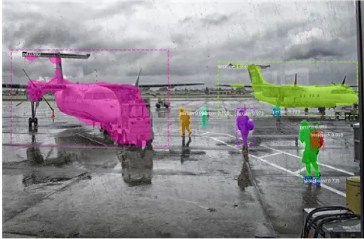
OverviewScene interpretation is an expression that stands for a collection of functions, such as object detection and classification, semantic seg-mentation or object tracking, that take an image frame, or a video, as input data and produce a symbolic representation of its visual content, usually associating geometry (the where part) and semantics (the what part), and often qualified by a score (see Fig. 6). These func-tions have been addressed since the beginning of artificial intelligence
and computer vision, with various paradigms. The modern approach, which is likely to last since it has demonstrated its capacity to equal or even surpass human performance in some contexts, involves a machine learning step able to specialize a complex parametric function to a dataset expected to be representative of the operating domain.
Description (white box)
Most of the current SI functions make use of Convolutional Deep Net-works; i.e., neural networks chaining a rather large number of layers with local two-dimensional filters. A typical example of such networks is depicted in Fig. 7.
The current trend of algorithm design is to integrate all of the neces-sary computations to complete the function in a common unifying deep network framework, making the learning step globally influence the whole chain, in a so-called end-to-end fashion. The resulting global function is therefore heavily dependent on the learning dataset that empirically specifies the function.
Difficulties regarding certification
The certification of software implementing a deep network should not modify current practices. Their architectures are homogeneous, exploit a small functional vocabulary (convolutional or fully con-nected layers, non-linear activation functions, pooling), make use of software development frameworks (Tensorflow, PyTorch, etc.) and specific libraries able to implement the network on a Graphical Pro-cessing Unit (GPU).
Figure 6 – Typical output of an SI algorithm, detecting objects of interest and their outlines. Obtained using Mask-RCNN [42]
RolAlign
class box
conv conv
However, the question of certifying data-driven AI algorithms – not software – is another matter. It appeared rather recently to be a very hot topic, since this kind of technology is expected to invade our life at rather short notice2.
One can summarize the problems brought by data-driven algorithm design in the following way:
• Specification by examples: the high dimensions of input and output spaces involved in perception functions make their for-mal and complete specification almost impossible. The usual way to describe the target function is to provide a distribution of good operating samples; i.e., a dataset of N input/output samples
{
,}
1N i i i
X Y = . This distribution is expected to describe both the input operating domain (what the possible input Xi
are) and the desired output predictions (the system should pro-duce Yi when fed with Xi). This way of specifying the per-ception function thus assigns a central role to the quality and representativeness of the dataset.
• Probabilistic requirements: the approach of specification by examples has a direct consequence on the way functional re-quirements are described: they depend on some uncertainty representation that expresses the lack of knowledge about the exact operating domain at the time of the algorithm design. Classical ways to define requirements are performance metric objectives, such as precision/recall for detection or retrieval, classification accuracy for recognition, mean square error for localization, etc. Many usual metrics are presented as trade-offs between several measures. This requirement description approach leads to several issues: 1) How do they relate to the full system hazard analysis?, 2) How are the acceptable trade-offs defined?
• Validation by testing: one consequence of specification by ex-amples is that validation also becomes data-driven. The ques-tion is to design fair evaluaques-tion protocols and metrics able to predict and estimate whether the requirements are satisfied. When dealing with machine learning, a key aspect is to find ways to compute unbiased estimates of the metrics and their variance, for instance by using cross validation.
• Robustness: deep networks are complex functional structures that are prone to instability or hyper sensibility that can be dis-covered, for instance, by adversarial optimization techniques. The question related to certification is to either assess a suf-ficient level of robustness, i.e., invariance to perturbation, or to detect potential instabilities or "attacks".
• Operational domain assessment: Defining an operational do-main through a dataset is inherently problematic and can be broken down into two issues: 1) How do we state whether a given input data will be correctly processed? 2) How do we describe the set of correctly processed input data – the opera-tional domain itself?
• Usability of formal verification: This has been a central approach in the aerospace domain, and is suitable when the problem can be expressed as a series of formal properties that have to be jointly satisfied, making possible the application of generic solv-ers for verification. Several studies have proposed the adapta-tion of this paradigm to neural network architectures, usually for 2 "A series of strategic themes [...] has to do with ethics, and the validation and
certification of AI technologies, the aim being confidence by all stakeholders in their results: from validation in terms of theoretical proof to explicability, transparency, causality and fairness." p. 65 of Villani’s Report (https://www.
low-dimensional problems, but the question of their generic us-ability for perception in very large dimensional spaces remains. • Intelligibility of the predictive process: DNNs follow a series
of complex nonlinear transformations of an input space, with a role for each step that is hard to assign clearly. The overall process is considered opaque. This makes the justification of both bad and good behaviors difficult, which is an obstacle to convincing of hazard-free functioning.
• Evolutivity and operational domain extension: the use of ma-chine learning techniques implies that the algorithm operational domain is restricted to what the dataset samples. Making the system evolve to a different context with new requirements will require a new learning phase, often with no non-regression guarantee.
State of the art
Several solutions to the above problems have been proposed, but mostly remain in the academic domain. We will follow the catego-rization described in "Developing specific certification objectives for computer-vision algorithms", with an emphasis on the last three to briefly give an idea of the current state of the art.
Run-time safety
Anomaly or novelty detection
A safe system should be able to warn its user when there is a risk of catastrophic consequences when exploiting its prediction; i.e., when it may be false, suggesting that it be rejected. In a prediction system, there are mainly two causes of rejection: uncertainty – the input data can be associated to more than one prediction – or novelty – the input data has not been considered during the design phase or is abnormal with respect to the underlying models exploited for the prediction. An uncertainty measure is a way to score prediction quality, and can be used either in combination with other scored predictions in a fusion step to improve the overall result, dynamically when using sequential filters for instance, or statically when exploiting redundancy. Another common usage of an uncertainty score is to consider it as a rejection indicator of abnormal behavior. We focus in this section on this last case.
Novelty, anomaly or outlier detection are synonyms of the same formal problem: deciding whether a given item of data belongs to an underly-ing distribution, usually described as samples, or as a set of charac-teristic prototypes. It does not address the question of designing a system that is robust to anomaly or outliers, but is aimed at equipping a predictor with an explicit rejection capacity or out-of-distribution detector. In machine learning, this problem is also known as the "one-class "one-classification". The expression "anomaly detection" sometimes refers to a way of building "saliency" detectors [10] – an anomaly being a pattern considered different from most of the others – but is not used for rejection purposes.
Novelty detection is not a new problem, and is used in many applica-tions, for instance in data stream analysis to detect intrusions (see [16, 61, 105, 72, 3] for various surveys). However, when data is highly dimensional, like images, applying generic methods is not powerful enough and depends on a projection over a much lower dimension feature space; e.g., Principal Component Analysis (PCA),
inferences. [105] discusses the issue of high dimension and its rela-tion to the dimensionality curse phenomenon.
Deep learning has been introduced in classical frameworks to better encode the data manifold, either for generic tasks (classification) or to specifically improve anomaly detection.
[15] describes a robust auto encoder that learns a nonlinear subspace that captures the majority of data points, while allowing some data to have arbitrary corruption, and evaluates their approach on three image datasets. [103] investigate two decision criteria (energy score and reconstruction error) for performing anomaly detection from an energy-based distribution representation computed on a deep network architecture. [26] presents a hybrid model where an unsupervised deep belief network (DBN) is trained to extract generic underlying features, and a one-class SVM is trained from the features learned by the DBN. [78] extends a one-class support vector approach to deep networks, using the same concept of a minimum volume hypersphere boundary. Another series of works exploits or modifies the output scores before decision, and uses them to detect out-of-distribution data coming from datasets that contain classes different from those found in the in-distribution.
[43] shows the performance of a baseline approach on several data-sets, relying on the idea that correctly classified examples tend to have greater maximum softmax probabilities than erroneously clas-sified and out-of-distribution examples, allowing their detection. [53] describes a method improving the detectability of out-of-distribution from the output scores by adding a small perturbation to the input and output temperature scaling. [22] proposes a method that learns a confidence score jointly with the actual prediction by retraining the last layer of a classification network, and uses it on the task of out-of-distribution detection. [60] also learns a confidence coefficient from the inner layers of a classification network and prediction, but with another loss measuring pairwise distance between different classes. [50] exploits a hierarchical class structure to detect data coming from new classes using confidence-calibrated classifiers, data relabeling, and a leave-one-out strategy for modeling novel classes under the hierarchical taxonomy.
As a binary decision problem, the evaluation of novelty detection algo-rithms depends on measures of false positive/false negative tradeoffs (AUC under ROC curve, Precision at given Recall). Most evaluation frameworks exploit data acquired from "real" situations, e.g., by label-ling several classes as outliers, or importing other datasets of similar origin and labelling them as novel (Cifar-10 vs. Imagenet). Algorithms are believed to be fairly compared under such settings. [12, 92] dis-cusses the suitability of available benchmarks (datasets and metrics) and compares several algorithms using such metrics. Their evalua-tion, however, is limited to low-dimensional data, and whether their conclusion scales to higher-dimensional perceptual data is open. However, using such evaluation approaches it is difficult to tell whether the state of the art of novelty detection algorithms is usable to assess on-line safety of data-driven perceptual algorithms.
Detecting adversarial examples
The discovery of adversarial examples has motivated the develop-ment of defense techniques able to counter or at least detect possible
attacks that have been demonstrated" [34]. This can be a clear issue for APES safety, the fear being that attackers may purposely design malicious examples to fool the system.
There are have been mainly three different ways to address defense against adversarial attacks:
• Modified training or input data: Changes in training data for learning or inputs during testing. [20] detects adversarial exam-ples by testing the validity of Neural Fingerprints, a set of fixed perturbations that are expected to have a controlled behavior when added to real data and not when added to an adversarial example. [96] studies a technique that augments training data with perturbations transferred from other models.
• Modified networks or learning: Modifying networks, e.g., by adding more layers/sub-networks, changing loss/activation functions, etc. For instance, [18] control the Lipschitz constant of each layer through regularization. [70, 69] exploit the no-tion of distillano-tion, i.e., the extracno-tion of class probability vec-tors produced by a first model to train a second one of reduced dimensionality without loss of accuracy, to generate more regu-larized deep networks. [88] augments model parameter updates with worst-case perturbations of training data in a Wasserstein ball. [59] studies the adversarial robustness of neural networks through a robust optimization perspective.
• Augmented networks: Using external models as network add-ons when classifying unseen examples. [101] uses feature squeezed (pixel encoding depth reduction and spatial smooth-ing) data to compare predictions from the original and the squeezed images. If a large difference is found, the image is considered to be an adversarial example.
The objective of these is to enable the system to be robust to adver-sarial attacks, or simply raise an alert to initiate further mitigation means.
A rather large number of recent studies on adversarial example detec-tors exploit the same intuition that they are far from being a manifold of clean data and can be identified by an out-of-distribution method in a given subspace spanned by inner activation layers of a deep neural network. [49] exploits a convex outer approximation of the set of acti-vations reachable through a norm-bounded perturbation for learning and testing. [62] detects adversarial examples by projecting the data to the learned manifold of clean images. [28] uses kernel density estimates and Bayesian uncertainty through a drop-out to detect out-of-distribution adversarial data. [55] learns a Radial Basis Function SVM to detect out-of-distribution data from the last stages of a deep network, where adversarial examples are expected to have the most different behavior. [52] defines a cascade classifier from convolu-tional filter outputs of various layers in a deep network to detect sarial data. [58] uses local intrinsic dimension estimation of adver-sarial regions and applies it to the detection of adveradver-sarial examples. [51] proposes a method for detecting any abnormal samples based on computing the Mahalanobis distance between class conditional Gaussian distributions with respect to (low- and upper-level) features of the deep models obtained through Gaussian discriminant analysis. The high interest of the research community has fostered several chal-lenges in designing defense methods against adversarial attacks: for instance, NIPS 2017: Defense Against Adversarial Challenge Attack3
![Figure 3 – Certification objectives required by DO-178C [76]](https://thumb-eu.123doks.com/thumbv2/123doknet/14484632.524791/6.892.172.721.66.624/figure-certification-objectives-required-c.webp)