Applications of optical parametric downconversion:
I. Self-phase locking;
II. Generation of entangled photon pairs in
3periodically-poled lithium niobate
by
Elliott J. Mason, III
Submitted to the Department of Electrical Engineering and Computer
Science
in partial fulfillment of the requirements for the degree of
Doctor of Philosophy in Electrical Engineering and Computer Science
at the
MASSACHUSETTS INSTITUTE OF TECHNOLOGY
June 2002
©
Massachusetts Institute of Technology 2002. All rights reserved.
A uthor .... ...
Departmnent of Electrical Engineering and Computer Science
May 17, 2002
Certified by...
Dr. Franco N. C. Wong
Principal Research Scientist
Thesis Supervisor
A ccepted by ...
...
...
...
Arthur C. Smith
Chairman, Department Committee on Graduate Students
MASSA 8W WSr TItT OfTECHNOLOGY
JUL
3 1 2002
Applications of optical parametric downconversion:
I. Self-phase locking;
II. Generation of entangled photon pairs in
periodically-poled lithium niobate
by
Elliott J. Mason, III
Submitted to the Department of Electrical Engineering and Computer Science on May 17, 2002, in partial fulfillment of the
requirements for the degree of
Doctor of Philosophy in Electrical Engineering and Computer Science
Abstract
Nonlinear optics plays a key role in many applications not only as a means of fre-quency synthesis and control, but also as a source of twin photons and other nonclas-sical states of light. Advances in nonlinear materials, including engineered nonlinear interactions through the use of quasi-phase matching, have increased the flexibility and performance of many nonlinear optical devices. One of the devices presented in this thesis is a 2:1 frequency divider based on self-phase locking in a type-II phase matched optical parametric oscillator. This device is investigated both theoretically and experimentally. Results are also presented on fabrication of periodically-poled nonlinear crystals for quasi-phase matching in lithium niobate and barium magne-sium fluoride. Finally, a high-efficiency frequency-nondegenerate twin photon source is implemented in periodically-poled lithium niobate.
Thesis Supervisor: Dr. Franco N. C. Wong Title: Principal Research Scientist
Acknowledgments
I am grateful to my thesis supervisor Dr. Franco Wong for advising me and supporting me over the past eight years. His guidance and insight have been a valuable resource for me, and it has been a pleasure to work under his leadership. I have also been fortunate to have as members of my thesis committee Prof. Jeff Shapiro and Prof. Erich Ippen. I have learned much from both of them over the years.
I would also like to acknowledge the programs that have provided my financial support. I started my research with three years of support under a National Science Foundation Minority Graduate Fellowship. I have also obtained support from both the Army Research Office and the Air Force Office of Scientific Research through two DoD Multidisciplinary University Research Initiative (MURI) programs. Much of my work on electric-field poling was done with support from the M.I.T. Lincoln Laboratory Advanced Concept Program. I am grateful for the use of the Lincoln Laboratory facilities as well as the help and support from members of group 83: Skip Hoyt, Kevin Ray, Bob Bailey, Leo Missaggia, Chris Harris, Jeannie Porter, and from members of group 82: John Daneu, Scott Buchter, T. Y. Fan, and Antonio Sanchez.
I have also been supported by the fellow members of the Optical Communications
group here at R.L.E. I want to express my heartfelt thanks to Marius Albota who put in many long nights with me in a cold lab looking for photon pairs. I want to thank Chris Kuklewicz for his valuable help with G programming for the poling and the data acquisition, and I want to thank Frieder Koenig who is continuing work on the photon pair generation experiment. I also appreciate the former members of our group that have given me support, friendship and advice over the years: Eser
Keskiner, Phil Nee, Joe Teja, Reggie Brothers, and Dicky Lee.
As my stay at M.I.T. comes to a close I have to acknowledge my family who has been there for me showing me love and encouraging me every step of the way. My
parents and grandparents have always kept me aware of their love and their prayers.
My wife Jessica has constantly supported me and shown patience and understanding
constant presence and provision in all the details of my life and has renewed my strength each day.
Contents
1 Introduction 12
1.1 Background . . . . 12
1.2 Parametric Downconversion . . . . 14
1.3 Applications and contributions of this research . . . . 16
1.4 Thesis organization . . . . 20
2 Self-phase locked optical parametric oscillator 21 2.1 Theoretical analysis of a SPLOPO . . . . 22
2.1.1 Basic Equations . . . . 22
2.1.2 Tuning Behavior . . . . 27
2.2 Observation of two distinct phase states . . . . 35 3 Periodically-poled nonlinear materials
3.1 Device fabrication . . . . 3.1.1 QPM grating design . . . . 3.1.2 Lithography and sample preparation . . . .
3.1.3 Electric-field poling . . . .
3.2 Periodically-poled BaMgF4 for VUV generation . . . .
3.2.1 Material Properties . . . .
3.2.2 Periodic-poling of BMF . . . . 3.3 Application of PPLN to frequency-nondegenerate entanglement source
3.3.1 PPLN Characterization . . . . 3.3.2 Coincidence counting . . . . 41 44 44 46 51 57 57 59 63 64 70
4 Conclusion
4.1 Sum m ary ... 4.2 Future W ork ...
A Grating Mask Specification and Generation A.1 Mask design parameters ...
A.2 AutoLisp Code ...
A.2.1 Mask specification files ...
A.2.2 Setup code library ...
A.2.3 Device drawing code library . . . . .
A.2.4 Area calculation code library . . . . .
A.2.5 Auxiliary code library . . . .
76 76 77 83 . . . . 8 3 . . . . 8 5 . . . . 8 6 . . . . 9 0 . . . . 9 5 . . . . 1 0 1 . . . . 10 5
List of Figures
2-1 Plot of thresholds normalized to K1K2/X 2 over the locking range for no
coupling (6O = 0), weak coupling (6O = 0.3), and strong coupling (6N =
1). The two threshold branches for the two coupled cases correspond
to the higher-threshold (solid) and the lower-threshold (dashed)
self-phase locked states. 6O is normalized to 'Kj K2 and L/1A2 = 0.4 1iK2. 28
2-2 Plot of the minimum threshold [(e )th] normalized to K1K2/X2 as a
function of the normalized cavity detuning VA1A2/KpK 2 for two
dif-ferent values of 6o/ /' 1K2: (a) 0.2, and (b) 0.5. . . . . 30
2-3 Contour plots of the total output powers for (a) the lower-threshold SPLOPO state and (b) the higher-threshold state under the condition
of weak coupling co/I/s1K2 = 0.3. The output power is scaled by
K1/K2/2 X2 . . . . . 32
2-4 Contour plots of the total output powers for (a) the lower-threshold SPLOPO state and (b) the higher-threshold state under the condition
of strong coupling 60/ VK1K2 = 1. The output power is scaled by
K1K2/2X2. . . . . 33
2-5 Plot of the signal-idler phase difference 01 - y2 as a function of the
normalized cavity detunings for the two SPLOPO states. The range of one state is from 0 to 7r (top half) while the other state spans from
0 to -7r (bottom half). The two states have the same phase difference
of 0 (heavy line A) and ir (modulus 27r, heavy lines B) at the two ends
2-6 Schematic of the experimental setup. SHG, second-harmonic
genera-tor; PZT, piezoelectric transducer. See text for other definitions. . . . 36
2-7 LO-signal interference under self-phase locked conditions (N/ = 20,
'Oh - 00) for (a) the p state, (b) the p state with a -r phase shift in both
#1
and 02, and (c) the n state. . . . . 38 2-8 Outputs at detectors DI and D2 (4'q = 1 , V/h= 1030) for (a) p stateand (b) n state. At V)h = 103' the D1 interference of the p state was m axim ized. . . . . 39 3-1 Schematic of lithium niobate sample after preparation with deposited
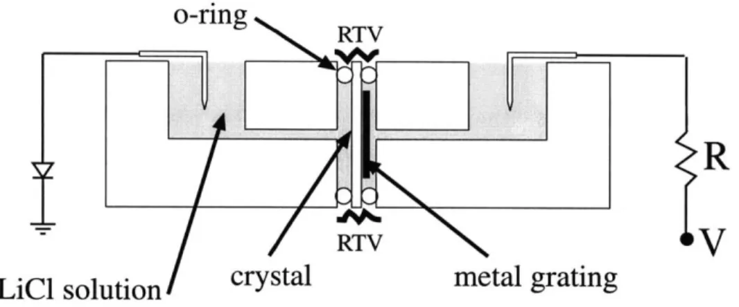
NiCr and insulating layers of fused silica and photoresist. Arrows in-dicate directions of domains after poling is completed. . . . . 51 3-2 The lithium niobate sample is shown here in the fixture which connects
to the high voltage circuit. The chamber in the plexiglas is filled with liquid electrolyte that makes electrical contact between the circuit leads and the crystal surfaces. . . . . 52 3-3 Simplified circuit schematic for poling of PPLN device. Vmon and Imon
are voltage and current monitors which are fed back to control the total charge transfer. The high voltage amplifier has a gain G = 2000. The diode prevents back-flow of current. . . . . 53
3-4 Traces of the voltage and current monitors out of the Trek 20/20 high voltage amplifier. LabVIEWTM is used to integrate the current and turn off the voltage when the total charge transferred reaches its target value. In this ideal case the current turns on and off sharply. . . . . . 54
3-5 More traces of the voltage and current monitors out of the Trek 20/20
high voltage amplifier. In this case the poling current started early and stopped late due to uncertainty in the turn-on poling voltage. .... 55 3-6 Top (left panel) and bottom (right panel) etched surfaces of PPLN
grating with a 22.4 pm period. The grating is only slightly over-poled with a 55% duty cycle. . . . . 56
3-7 Plots of the unpolarized optical transmission for two crystal lengths
and the resulting inferred absorption coefficient. . . . . 58 3-8 Period of QPM grating needed to generate 157 nm with sum frequency
generation. Plot versus shorter wavelength, for d33 (dashed) and d32 (solid ). . . . . 60
3-9 Voltage and current of 19 pulses used to pole the BMF grating. . . . 61
3-10 Image of +z-face of periodically-poled BMF using an environmental
scanning electron microscope. The grating period is 19.2 pm and the white scale bar corresponds to 50 pm . . . . 62 3-11 Experimental setup for the DFG measurements taken to evaluate the
poled crystals. A Si PIN photodiode and a lock-in amplifier was used to detect the generated light. The LP filter is a long-pass filter with
cut-off frequency ~700 nm . . . . 66 3-12 DFG conversion efficiency of the 3rd-order 22.1 pm period grating as
a function of temperature with FWHM of 1.3 . . . . 68 3-13 DFG conversion efficiency of the 1st-order 7.5 jim period grating as a
function of temperature with FWHM of 1.60 . . . . 69
3-14 Wavelength vs. temperature tuning curve for 21.6 pm period grating of PPLN. ... ... 70 3-15 DFG conversion efficiency of the 3rd-order 21.6 pm period grating of
PPLN as a function of wavelength with FWHM of 1.26 nm. . . . . . 71 3-16 Setup for coincidence counting of generated photon pairs. . . . . 72 3-17 Timing of conditional coincidence counting. . . . . 73 3-18 Conditional detection probability of idler photons given a signal photon
is detected. Normalized histogram of counts in 2-ns time bins over a 20-ns window . . . . 75
4-1 Dual coherently-pumped downconverter setup. The signal outputs are combined in one PBS and the idler outputs are combined in another PBS. Coincidence counting is performed as before, with HWPs and polarizers to project the outputs onto an arbitrary linear polarization basis. . . . . 78
4-2 Conditional coincidence counts normalized to give the probability of detecting an idler photon, given a signal photon has been detected. Plotted for various HWP angles from 0' to 900. The maximum value at a HWP angle of 450 corresponds to rotation of the idler polarization
by 90' such that the orthogonal state is detected. ... 79 A-i Shown here are the definitions of the parameters specified when
design-ing a QPM gratdesign-ing device with contact pads, and the corresponddesign-ing device with contact pads only. . . . . 84
List of Tables
3.1 Measured DFG conversion efficiency and comparison with theory based
on nominal value of d3 3 = 27.2 pm/V. Different focussing where
Chapter 1
Introduction
1.1
Background
In a linear medium electromagnetic fields of different frequencies propagate without interacting with each other. Expressed in terms of input-output relations between electromagnetic fields, the total output can always be expressed as a linear combina-tion of the individual output fields corresponding to different input frequencies. For any particular frequency the presence or absence of fields at other frequencies does not affect the evolution of the field. In optical materials the simplest (and strongest) form of nonlinearity is the second-order nonlinearity described by the second-rank nonlinear susceptibility tensor XM. The lowest order nonlinearity in isotropic media such as glass is third-order since those of second-order only exists in media lacking inversion symmetry. There are many noncentrosymmetric crystals which possess a second-order nonlinearity by which an electric field induces a polarization propor-tional to the square of the field. This gives rise to an exchange of energy among fields of different frequencies, and is referred to as three-wave mixing.
The first known direct observations of the effects of the second-order nonlinearity are in the experiments of Pockels in 1893. One of the interacting fields was a static field giving rise to what is known as the electro-optic effect. The DC electric field strengths attainable were high enough to observe an induced birefringence experienced
been performed to attempt to observe optical nonlinearity as suggested by the words of Isaac Newton in his Opticks [1] in 1704: "when one sort of Ray hath been well parted from those of other kinds, it hath afterwards obstinately retained its colours,
notwithstanding utmost endeavours to change it".
It was the discovery of the laser or the 'optical maser' [2] that was the key to enabling true nonlinear optical frequency mixing. The field of nonlinear optics has continued to flourish for most of over four decades since the demonstration of the first lasers. The first milestone was the observation of second harmonic generation by Franken et al. [3] in 1961. 694-nm light from a pulsed ruby laser was sent through a quartz crystal to generate 347-nm light. Closely following this was a demonstra-tion of sum frequency generademonstra-tion [4]. These experiments suffered from the effects of dispersion which caused the interacting fields to have different phase velocities in the material, thus limiting the efficiency of the power transfer.
The importance of phase matching was pointed out independently by scientists from Bell Laboratories [5] and Ford Motor Company [6] who demonstrated that ma-terial birefringence could be used to cancel the effects of dispersion. This is known as birefringent phase matching. Another means of phase matching was suggested by Armstrong et al. [7] which involved compensating for the dispersion by periodically changing the sign of the nonlinear coefficient in the material to reset the relative phases after they have slipped 180 degrees out of phase. However, no practical means existed to accomplish this technique, now known as quasi-phase matching (QPM), so birefringent phase matching remained dominant for the following few decades. Over the years there have been improvements in the quality and availability of nonlin-ear materials and laser sources to extend the wavelength range of birefringent phase matching. There were also new techniques developed contributing to the advance of the field of nonlinear optics including Q-switching, optical parametric oscillation, and nonlinear interactions in waveguides. Nonlinear optics has been used for frequency converters, amplifiers, tunable sources, and important applications in fields such as frequency metrology and quantum optics.
de-vices. Though QPM had been demonstrated before, the methods used had limitations that made it impractical. When electric field poling with a periodic metal electrode was demonstrated by Yamada, et al. [8] in 1993 many experiments followed that firmly established this method as a powerful technique for phase matching. Now, instead of finding a particular angle for a set of wavelengths that could be phase matched in a particular material, any wavelengths in the transparency range could be matched as long as a suitable electrode grating could be fabricated. Lithium niobate, already a widely available material used for its electro-optic and acousto-optic properties, be-came a popular material for QPM because of its high nonlinear coefficient and wide transparency range. Details of QPM and fabrication of periodically-poled lithium niobate (PPLN) are covered in chapter 3.
1.2
Parametric Downconversion
Energy conservation for any three-wave mixing interaction requires that the frequen-cies of the three interacting fields be related by
W (s + w, (1.1)
where the subscripts refer to the pump ('p'), signal ('s') and idler ('i') fields. These labels correspond to the process known as optical parametric amplification (OPA) where energy is transferred from a strong 'pump' field to amplify a weak 'signal' field. In addition to the requirement on the frequencies in (1.1), energy conservation also requires that energy will flow into a third 'idler' field. Equation (1.1) can also be interpreted according to the photon interactions by noting that every pump pho-ton created (destroyed) requires that one signal and one idler phopho-ton be destroyed
(created).
In an interaction where a new frequency is generated from fields at two input frequencies there are two standard three-wave mixing schemes. One is sum frequency generation (SFG) where fields at frequencies w, and wi mix to generate a field at a
higher frequency wp = w, + wi. The other is difference frequency generation (DFG) where fields at frequencies wp and w, mix to generate a field at wi = wp - w,. As explained above, this is also called optical parametric amplification when the process is used to amplify a weak input field at w,.
The two main applications demonstrated in this thesis make use of the process known as spontaneous parametric downconversion (SPDC). Unlike OPA, it only re-quires one input field. Classically, a single monochromatic input field does not un-dergo downconversion in a X . However, according to quantum theory, there is a nonzero probability that an 'input photon' at wp undergoes SPDC into two 'output photons' at w, and wi. This process is known as parametric fluorescence. Parametric amplification of single signal or idler 'noise' photons by a pump field is also known as parametric superfluorescence [9]. This type of interaction is useful for generat-ing pairs of signal and idler photons that are entangled in energy and momentum. In this work we use SPDC in a PPLN crystal to achieve highly efficient, tunable, frequency-nondegenerate entangled photon pair generation.
When one or both of the downconverted fields are resonated in an optical cavity the parametric gain and optical feedback enable oscillation to occur. The parametric gain increases with pump power. The oscillation threshold occurs when the round trip gain and loss are equal. When pumped above threshold the SPDC seeds the conver-sion such that the circulating fields build up to a steady-state value. In steady state the gain remains clamped at this value and increased pump power above threshold increases the signal and idler outputs. This is known as an optical parametric oscil-lator (OPO). When only one field is resonated in a singly-resonant OPO (SRO) the frequency with the largest gain and smallest loss, such that the oscillation condition is met, determines the signal and idler frequencies within the broad phase-matching bandwidth. There exists such a frequency for every cavity length. A doubly-resonant OPO (DRO) requires both fields to be resonant which places an extra constraint on the frequencies such that it only oscillates in a discrete set of longitudinal cavity modes. Both SROs and DROs have been used extensively as sources of continuous-wave (cw) or pulsed light. They enable high-power frequency conversion and expand
the ranges of frequency, power, and tunability that can be achieved over conven-tional laser sources. In this work we demonstrate a new application of an OPO: a 2:1 frequency divider based on a self-phase-locked cw DRO.
1.3
Applications and contributions of this research
CW OPOs have properties which make them useful sources of light for a wide range of applications. They have played important roles as tunable sources for high-resolution spectroscopy, and as fixed stable sources for precision measurements and optical fre-quency metrology. Progress in nonlinear materials (including periodically-poled crys-tals), and stable solid-state pump lasers have contributed to the interest in cw OPOs as practical tools. Tunability over broad operating ranges of tens to hundreds of nm have been achieved with techniques such as the use of broadband high-reflection mir-rors [10] and novel grating designs [11]. For spectroscopy OPOs can provide substan-tial amounts of power, with narrow linewidths and large continuous (mode-hop-free) tunability. Continuous tuning of both SROs and DROs have been demonstrated. An implementation of molecular spectroscopy was demonstrated using a pump-resonant SRO [12] with a tuning range of over 1 GHz. Due to their discrete longitudinal cavity modes, DROs require a servo to lock onto a single cavity mode. Nevertheless, contin-uous tuning in DROs has also been demonstrated using pump tuning (over a range of 8 GHz) [13], or using a dual-cavity design (over a range of 900 MHz) [14].
In some situations it is desirable to remove this degree of tunability freedom and fix the output frequencies. For example, the subharmonics of an OPO can be tuned and locked to precisely known ratios of the pump frequency. Such devices are known as optical frequency dividers [15, 16]. Used in conjunction with optical frequency comb generators they played an important role in optical frequency metrology in the implementation of optical-to-microwave frequency chains [17]. More recently, the role of optical frequency dividers has been dramatically reduced by breakthroughs that utilized octave-spanning optical frequency combs generated from modelocked lasers [18, 19]. They can still provide an important function of precisely dividing an
input frequency by two or some other predetermined ratios.
Graham and Haken first investigated the quantum noise characteristics of OPOs. They showed that the sum of the signal and idler phases follows the phase of the pump, and the difference of the signal and idler phases undergoes a phase diffusion process from interaction of the signal and idler modes with vacuum fluctuations [20]. Thus, in order to achieve phase-coherent frequency division the signal and idler waves must be phase locked. One method used to achieve a stable phase locked output is by means of an external phase-locked loop [21]. This method is limited by the electronic servo bandwidth. An alternative method is an internal all-optical method: self-phase locking. This was first observed in a 2:1 frequency divider based on a type-I phase matched DRO [22]. When tuned to frequency degeneracy the co-polarized signal and idler experience strong mutual coupling and they become phase locked to the pump with either a zero or -r relative phase. In contrast, the signal and idler fields in a type-II phase matched DRO are orthogonally polarized and can be smoothly tuned through frequency degeneracy with no locking occurring. In this thesis I show that it is possible to obtain self-phase locking in a type-II phase-matched DRO and that its characteristics are very different from that of a type-I phase-matched DRO.
By inserting an intracavity waveplate to rotate and thereby couple the orthogonally
polarized fields self-phase locking occurs at frequency degeneracy [23]. A theoretical analysis [24] of this device shows that this mutual signal-idler coupling leads to two steady-state oscillation modes, both of which we observed experimentally. This thesis covers both the theoretical analysis and the experimental demonstration of the self-phase locked type-II self-phase matched DRO.
Based on the results of our work, Lee et al. demonstrated self-phase locking in a 3:1 frequency divider based on a type-I phase matched DRO through the use of nonlinear signal-idler coupling [25]. A dual grating PPLN crystal was used to provide one grating section for the downconverter and a second grating section to phase match mixing between the signal and idler which were in a 2:1 ratio. Theoretical analysis of this type of device has also been done investigating the resonant X(2) : X(2) cascaded second order nonlinearity and the resulting self-phase locking behavior [26].
Quantum optics is another area where cw OPOs have played an important role as nonclassical light sources. Many experiments have been performed demonstrating squeezing when pumped below threshold (as a cavity-enhanced OPA), and sources of intensity-correlated twin-beams when pumped above threshold. It was a correlation measurement using a cw OPO that provided the first experimental demonstration [27] of the original Einstein-Podolsky-Rosen paradox utilizing continuous quantum vari-ables where quadrature-phase amplitudes played the role of the canonical position and momentum variables. The European Union has a consortium [28] of universities in Germany, France, UK, and Denmark focusing on the use of continuous quantum variables in quantum communications. A primary goal is quantum teleportation of continuous quantum variables using various sources of "bright quantum light." One of the sources utilizes the same configuration as the type-II self-phase locked OPO first demonstrated in this work. They propose "...to operate a type II OPA in the frequency degenerate regime by injecting it with an external field, or by 'self injection' (coupling of the two orthogonally polarised fields inside the cavity). By separating of the two outgoing polarisations, one expects to produce beams with entangled quadra-ture phase amplitudes."
A large area of research is devoted to sources of entangled pairs of photons
pro-duced via SPDC in a nonlinear crystal. Entangled photon pairs are a key element in many systems that rely on quantum information. The goals of such systems are implementation of quantum communications, quantum computational algorithms, or quantum cryptography. Many particular applications such as teleportation [29] make use of polarization-entangled photons. One of the main goals of many experiments is to demonstrate practical "bright" entangled sources with a high pair production rate [30]. One way to boost the production rate is to place the crystal in a cavity for the pump field, thus increasing the efficiency of the SPDC [31].
One recently proposed quantum communication system [32] aims to achieve long-distance high-fidelity teleportation making use of polarization-entangled photons and trapped-atom quantum memories [33]. The polarization state of the photons can be transferred to the long-lived hyperfine levels of ultra-cold trapped rubidium atoms.
This system allows for quantum information in the form of qubits to be transmitted reliably and stored for later processing. A novel ultrabright narrowband source of polarization-entangled photons is proposed [34] to achieve efficient coupling of photons into the optical cavity containing the atom which has a ~6 MHz bandwidth at a
795 nm center wavelength. This source produces narrowband polarization-entangled
photon pairs using a doubly resonant optical cavity for signal and idler. Pumped well below threshold, the OPA produces a high flux of photon pairs over the bandwidth defined by the OPA cavity that is designed to match the trapped-atom memory. A single OPA would produce signal and idler outputs correlated in polarization, but not in a polarization-entangled state. Two such OPAs can be combined in such a way that each of the signal and idler outputs is in a superposition state of two orthogonal polarizations coming from the two OPAs. Such a scheme does not require that the signal and idler be frequency degenerate as do many typical downconverter sources. In the proposed system this feature is utilized to make the signal match the
795 nm excitation wavelength of a local trapped-Rb quantum memory, and the idler
at -1600 nm for low loss fiber optic transmission to a remote location. The first step towards such a source is implemented in this thesis using PPLN pumped by a 532 nm pump to generate photons at 795 nm and 1609 nm. The benefits of PPLN in providing a flexible and efficient means to generate entangled photon pairs is beginning to be recognized [35, 36]. We demonstrate efficient generation and collection of photon pairs into single-mode fibers by time-coincident counting of the signal and idler photons.
Another application demonstrated in this thesis was also made possible by electric-field poling of ferroelectric crystals. Conventional materials for generation of wave-lengths in the UV and vacuum UV spectral regions suffer from limitations such as
solarization, large Poynting-vector walk-off, and limited vacuum-UV transparency. One material, barium magnesium fluoride (BMF), not only has excellent transparency down to <140 nm, but is also resistant to solarization. However, the birefringence is not strong enough to birefringently phase match interactions for generating wave-lengths this short. We have shown that it is possible to use electric-field poling to enable QPM in this material [37]. This also eliminates Poynting-vector walk-off since
QPM utilizes noncritical phase matching. We also use an environmental scanning
electron microscope to examine the quality of the domain reversal and find that high-fidelity patterning of a 19.2-mm-period grating is possible, an important step for showing feasibility of obtaining shorter period gratings.
1.4
Thesis organization
This thesis demonstrates devices based on optical parametric downconversion and developments made in periodic poling of ferroelectric crystals. Chapter (2) intro-duces and describes the self-phase locked OPO. It starts with a theoretical analysis and illustrations of some basic properties of the device in section (2.1). Then in sec-tion (2.2) the observasec-tions made from an experimental realizasec-tion of the device are presented. Chapter (3) covers periodic poling in two nonlinear crystals, lithium nio-bate and BMF, and the advantages they bring to particular applications. A detailed description of all the steps involved in fabricating PPLN is contained in section (3.1). Section (3.2) then covers the first-time demonstration of periodic poling in the ma-terial BMF enabling UV generation through QPM. Then the use of PPLN for as a high-efficiency source of frequency-nondegenerate photon pairs is discussed in sec-tion (3.3) with a demonstrasec-tion of nonclassical time correlasec-tions through coincidence counting. The thesis concludes in chapter (4) with a summary of the main results and a discussion of future directions for work on the photon pair source.
Chapter 2
Self-phase locked optical
parametric oscillator
Self-phase locking is a means of achieving a mutually phase-locked (and frequency degenerate) signal and idler output in a type-II phase-matched doubly-resonant OPO without the need for an external phase-locked loop [21]. By inserting an intracav-ity quarter-wave plate (QWP) a linear coupling between the orthogonally polarized signal and idler fields allows a form of mutual injection locking at exact frequency degeneracy. Two self-phase locked modes with different thresholds and signal-idler phases are possible. This is illustrated here both theoretically and experimentally along with other properties of this device [24, 23].
A detailed theoretical model of the steady-state characteristics of the self-phase
locked OPO is covered in section (2.1). Section (2.2) describes the experimental observations of self-phase locking in a type-II phase-matched KTP OPO. We observed two distinct phase states that differed by nearly 7r in their signal-idler phase difference. Attention is focussed on how these two states were identified. These observation prompted the analysis of section (2.1).
2.1
Theoretical analysis of a SPLOPO
In section 2.1.1 the basic equations of both the normal, uncoupled OPO and the self-phase locked OPO are introduced and solved. As a first step, and in order to introduce the relevant notations and equations, we consider a nondegenerate, doubly resonant OPO (DRO) without an intracavity waveplate. In a DRO the signal and idler fields are resonated in a cavity which contains the nonlinear crystal. Since we are covering self-phase locking phenomenon under type-II phase matching, we will assume a crystal that is phase matched for orthogonal signal and idler polarizations (set by the ordinary and extraordinary crystal axes) given by unit vectors i and
i2 for signal and idler, respectively. We then modify the equations introducing an intracavity QWP for self-phase locking. The orientation of the fast and slow axes of the QWP are defined according to the angle /)q between the QWP's fast axis and the fixed direction i2. In section 2.1.2 numerical results are plotted to illustrate the
regimes of operation for various values of the free parameters.
2.1.1
Basic Equations
The DRO converts a pump field of frequency wp into signal and idler fields of fre-quencies w, and w2, respectively. Energy conservation yields the relationship among the frequencies w, = w1 + w2. Furthermore, the interaction is assumed to be phase matched such that kp = ki + k2. Let Ap, A1, A2 be the complex amplitudes of these
three fields, normalized in such a way that JAi 2 (i = p, 1, 2) gives the corresponding
photon flux in units of photons/second.
The pump is assumed to be nonresonant and takes a single pass through the crystal. The signal and idler modes are allowed to have some nonzero detuning from the nearest cavity resonance denoted by Aj (i = 1, 2), where
A, = -L(wi) - 2rpi. (2.1)
c
L(wj) is the cavity roundtrip optical length at frequency wi, which can be
experimen-tally changed either by moving one mirror of the cavity or by changing the crystal temperature and therefore its index of refraction. The double resonance condition implies that A,
<
1 and A2<
1, i.e., the output fields are near cavity resonanceand within a cavity linewidth of the resonance peaks.
When the DRO is in the steady-state regime the roundtrip gain and losses ex-perienced by the resonant fields are equal and small. The fields can therefore be approximated as varying linearly over the length of the crystal: the signal and idler fields increase and the pump decreases linearly over the length of the crystal. The circulating fields A, and Ai are approximately constant inside the cavity. The nonres-onant pump can be depleted by a significant amount. However, as shown below, the magnitude of AP, defined here as the mid-crystal pump field amplitude, is clamped
at its threshold value even at full depletion [38].
By requiring in steady-state that the field amplitude is unchanged after one round
trip in the cavity, one obtains the following well-known classical equations for the three fields:
(Ki - i*Ai)A = XAA*1, (2.2)
(K2 - iA2)A2 = XApA*, (2.3)
1
AP= e- -XA1A 2, (2.4)
2
where X is the normalized crystal nonlinearity (taken real, because the crystal is assumed to be lossless and exactly phase matched), ep (its phase set to zero) is the
pump amplitude at the input of the crystal, and ,i (with ,i < 1) is the roundtrip
cavity field loss coefficient. The pump is assumed to make a single pass through the crystal and the cavity losses are lumped together and assigned to a single output coupling mirror with power reflection coefficient Ri (i = 1, 2) given by Ri = (1 - Ki)2.
It is well-known that these equations have a nonzero solution only when
(2.5)
which, with the help of Eq. (2.1), sets a well-defined value to the signal and idler frequencies for a given longitudinal mode number pi. Expressing the complex field amplitudes in terms of the real-valued amplitudes and phases Ai = riew, the following relations hold 2 2 X r = K1K2 + A1A2, (2.6) r1 2
A
2 - = A (2.7) r2 All (P1 + 92 =pp + tan- . (2.8)The mid-crystal pump power is independent of the pump input power e2. The ratio of the signal and idler circulating powers is determined by the ratio of their detunings (which is the same as the ratio of their losses). The sum of the signal and idler phases is fixed relative to the pump phase. However, their difference is undetermined and undergoes a phase diffusion process [20, 39].
The oscillation threshold occurs when the input pump power is equal to the value given by Eq. (2.6):
1
(e )th = =2 (KiK 2 + A1A2). (2.9)
x
Above threshold, the photon flux transmitted through the output coupler (including the loss associated with it) is given by P = 2rir2 (i = 1, 2). As expected, the total photon flux for the signal and idler are equal: P1 = P2. The total output power can also be expressed in terms of the input pump power and other cavity parameters
P,,.= P + P2 = 2 ir2 + 2K2r2 (2.10)
= 8e O F[ - (A1/K1)2 - i], (2.11)
where Fp = eP/e is the number of times the DRO is pumped above the zero-detuned threshold e= i 2/X2. The circulating signal and idler powers that determine the
output powers P and P2 are related to Pst by the following expressions 2 A2 Pout (2.12) ,1A2 + K2A1 2 2 rA Pout (2.13) 2 K 1A2 + K2A1 2
For the self-phase locked OPO, we now modify the equations for the usual DRO
by inserting a linear coupling term between the signal and idler fields. Experimentally
this can be easily achieved in a type-II phase-matched DRO with an intracavity QWP in a standing-wave cavity configuration. A double pass through the QWP is equivalent to a single pass through a half-wave plate, rotating each field by twice the angle 01 between the wave plate and the crystal axes. The equations for the projections of the fields on the ordinary and extraordinary crystal axes are now
(K1 - iiA)A 1 = xApA* + cA 2ei(W1 W2)t, (2.14)
(K2 - iA2)A2 = XApA* - f*Aie-(1-W2)t (2.15)
where e is the mutual-injection coupling constant due to the QWP. As required by energy conservation, the injection coupling constant in Eq. (2.15) is the negative complex conjugate of that in Eq. (2.14). Writing e = co exp(i6), we have co oc sin 2
'Oq .
The coupling strength co also depends on mode matching and Poynting-vector walk-off. 0 is the roundtrip phase shift between the signal and the injected idler.
This DRO has a frequency degenerate regime with time independent values for
A1 and A2 with the condition wi - W2= 0, i.e., w = W2= wp/2. This corresponds to the self-phase locked OPO (SPLOPO), working at exact frequency degeneracy, where
the coupling between the two oscillating fields leads to mutual frequency locking. Experimentally this regime is entered when the signal-idler frequency difference is tuned to within the capture range that depends on the coupling strength as in laser injection locking. The theoretical analysis here covers only the steady-state solutions
within this regime where Eqs. (2.14) and (2.15) take the simplified form
(ri - iAi)A1 = xApA* + cA 2, (2.16)
(r2 - iA2)A2 = xA A* - C*Aj. (2.17)
This set of equations has a nontrivial solution (A1 # 0, A2 = 0) when its determinant
is zero. This leads to the following equation that is necessary for the self-phase locked operation
Xr - Kis2 - A1A2 - CO)2 + (K1A2 - K2A1) = 401A2
This equation has real solutions for the pump field amplitude rp if and only if
4,EA 1A2 > (ti1A2 - K2A). (2.18) As A1 and A2 can be tuned by changing external parameters, such as the cavity length
or the crystal temperature, condition (2.18) defines an operating range for these pa-rameters within which the locking phenomenon takes place. The oscillation threshold is still defined as the clamped mid-crystal pump power: (e2)th = r2. However, there are now two solutions for r . When condition (2.18) is satisfied the SPLOPO may oscillate in one of two locked modes, each with a different threshold given by
2 2 ~1 2 ± +AA )2.
x r = K1K2 + A1A2 + Ci 4cA1A2 - (K1A2 - K2A 1)2. (2.19)
The ratio of the signal and idler circulating powers is still given by the ratio of their detunings as in Eq. (2.7). However, now this ratio is no longer equal to the ratio of their losses, but can vary over the locking range determined by condition (2.18).
The signal and idler sum and difference phases are given in the following equations
0f~ 4-r
2 - I~~ I[1 (Ki ) A2 -
A
(221L2o k =V i1 k - 'V 2 (2.21)
where the ± signs depend on the sign of A, and on the oscillation mode. The sine of both 01 + 02 - po, and 01 - V2- 0 can also be obtained from Eqs. (2.16) that can uniquely determine the signs in Eqs. (2.20) and (2.21) which clearly show that the phases V, and 02 are uniquely determined by the various operating parameters, and
hence are both locked to well defined values that are related to the mid-crystal pump phase Wp. Unlike the conventional OPO in which the signal-idler phase difference undergoes phase diffusion, the SPLOPO has a fixed phase difference and fixed signal and idler phases. Note that these phases take on different values in the two possible oscillation modes.
The total output power Po0 t as defined by (2.10) can be shown to be a solution of the following equation
0 x ou +
16(KlA 2/A 1
+
2K1K2 + 2Ai/A 2) 4+ (KIK2 + A1A2 + 4coAlA 2 - (K1A 2 - K2A1)2) - x2e . (2.22)
The signal and idler amplitudes are still related to the total output power by Eqs. (2.12). Above threshold, there is only one positive solution for Pont in Eq. (2.22) for each oscillation mode.
2.1.2
Tuning Behavior
Based on the above solutions we now investigate the tuning characteristics of the SPLOPO. The linear coupling strength Eo is an adjustable parameter that is ex-pected to have a significant effect on the SPLOPO tuning behavior. Physically EO is determined by the amount of polarization rotation due to the intracavity waveplate as described above. When we speak of tuning we do not mean the tuning of the output frequencies, which are fixed at wp/2 in the self-phase locked regime. Instead, the tunings that we are interested in are those of A1 and A2 which can be adjusted
by varying the crystal temperature, the physical length of the cavity, or even the
sep-arate beam paths inside the cavity (due to walk-off). Changes in A1 and A2 within
the locking range affect the thresholds, the output powers, and the signal and idler phases.
2.5-2.0
1. -1.0 ---F-E0 0. 300.5-0.0
-1
-0.6
-0.2
0.2
0.6
1
cos((p-
P
20
Figure 2-1: Plot of thresholds normalized to K1K2/X2 over the locking range for no
coupling (Eo = 0), weak coupling (co = 0.3), and strong coupling (fo = 1). The
two threshold branches for the two coupled cases correspond to the higher-threshold
(solid) and the lower-threshold (dashed) self-phase locked states. co is normalized to
K1 K2 and VA1A2 =
0.41rK2-From the threshold Eq. (2.19) it is clear that the geometric mean of the roundtrip
cavity losses fIr 2 serves as the normalization factor to which other parameters
should be compared. Figure (2-1) shows the threshold power (e2)th over the
lock-ing range for the two SPLOPO states for weak coupllock-ing with fO/ K1K2 = 0.3 (or
defined by condition (2.18) can be rewritten as
I - 2 A I ) = cos(91 - 2 - )|. (2.23)
It is therefore appropriate to represent the locking range axis in Fig. (2-1) by -1 <
cos(0 1 - 02 - 0) 1. We note that the locking range condition constrains only the ratio A1/A 2 and, in order to completely specify the operating conditions for Fig.
(2-1), we set the geometric mean of the cavity detunings vA1A2 = 0.4VtNiK2. For reference, the straight line in Fig. (2-1) represents the threshold for the uncoupled case (Eo = 0) given by Eq. (2.9). There are two oscillation threshold branches for
each coupling case corresponding to the two states of the SPLOPO. At the center of the locking range, where K1/A1 = k2/A2, the threshold difference between the two
branches is maximum and equals 4EO6 A1A2. As a result, this threshold difference is
much more pronounced for the case of strong coupling. We note that in Fig. (2-1)
the minimum threshold for the weak coupling case (Eo/ "/-1i2 = 0.3) is actually lower
than the uncoupled case (co = 0).
In general the threshold is higher for a larger E0. However, near the center of the locking range it is possible for the strong-coupling threshold to be lower than the weak-coupling threshold. At the center of the locking range the threshold difference between the two oscillation modes is maximum. In this case the lower threshold is
[e
()th]m = 2 (K1 K2 + ( A1A2 - eO)2). (2.24)
We see that for a given coupling strength the minimum threshold at the center of the locking range depends on the detuning. For a given pair of signal and idler detunings, this minimum threshold is reduced with respect to the uncoupled case if 4A1A2 >
We note that the minimum threshold in the SPLOPO is always above or equal to the minimum threshold for the uncoupled case at zero detuning (Al = A2 = 0) which is
K1K2/X2.
"c
1.61.5
-
S1.4-(a)
"1.2-
(b)
c
1.1-Z
1.0
0
0.2
0.4
0.6
0.8
1
Normalized detuning
Figure 2-2: Plot of the minimum threshold [(e2)th] m normalized to K1K2/X2 as a
function of the normalized cavity detuning A1A2/rri12 for two different values of
co / / 1K2: (a) 0.2, and (b) 0.5.
two different values of co/K iK1 2 = 0.2, 0.5. The two curves look identical except for
a displacement along the cavity detuning axis, as Eq. (2.24) clearly indicates. The
threshold reaches the minimum of unity (normalized to K1K2/X 2) at -A
1A2 = co. It illustrates that for a given coupling co the minimum threshold can be obtained with adequate cavity detuning and that this minimum threshold does not occur at zero detuning, as is the case for the uncoupled OPO.
While it is useful to plot the threshold values over the locking range it is perhaps more intuitive to study the tuning behavior as a function of the individual cavity detunings A1 and A2. Figure (2-3) shows contour plots of the total output power
Pout of Eq. (2.22) of the (a) lower-threshold and (b) higher-threshold SPLOPO states as a function of the normalized cavity detunings, A1/ri and A2/K2, for weak coupling
2.5(K1 K22/X 2). The area within the two straight lines is within the locking range and the shaded areas denote above-threshold operation. The contour lines are scaled by
K1i2/ 2X2 and the higher output power is in darker shades. For this weak coupling case the operating regions and the output power levels for the two SPLOPO states are quite similar, which is expected because the linear coupling term which lifts the degeneracy of the two states is small. One apparent difference in Fig. (2-3) is the convex curvature of the contour lines for (a) the lower-threshold output power, and the concave curvature for (b) the higher-threshold output power, when viewed toward the origin.
For strong coupling co/ K1K2= 1, Fig. (2-4) shows that the two SPLOPO states
have very different operating regions and output powers for pumping at 2.5x above the minimum threshold. The lower-threshold state (a) in Fig. (2-4) has a much broader operating region in the A1, A2 space than that for the weak coupling case
Fig. (2-3(a)). The operating space of the higher-threshold state (b) in Fig. (2-4) is confined to a much smaller area because the strong coupling makes the threshold significantly higher in most regions. In addition, the output powers of the high-threshold state in Fig. (2-4(b)) are significantly lower than that of the lower-high-threshold state in Fig. (2-4(a)). Note that the convex-concave features of the contour lines remain in the strong coupling regime.
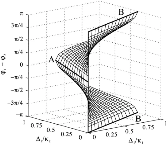
The signal-idler phase difference 01 - cp2 of the self-phase locked OPO determines
the polarization of the output. This phase difference ranges from 0 to 7r for one mode and from 0 to -7r for the other oscillation mode (for 0 = 0). The exact
phase-difference angle depends on the operating point within the locking range. Therefore the output polarization can be manipulated by changing the operating point of the OPO. Figure (2-5) shows the signal-idler phase difference (0 is set to zero for conve-nience) for the two SPLOPO states as a function of the normalized cavity detunings. We assume moderate coupling of co/ K'i 2 = 0.5 for Fig. (2-5). We note that near
the center of the locking range the difference in the relative phase difference yc1 - 'p2
1.8
-
(a)
2
01.4
1.0
0.6-0.2
-1.8 -
(b)
<
1.4
2
01.0 -4
0.6
0.2
0.2
0.6
1.0
1.4
1.8
Idler detuning
A2/K
2Figure 2-3: Contour plots of the total output powers for (a) the lower-threshold SPLOPO state and (b) the higher-threshold state under the condition of weak
cou-pling co/ 1vK2 = 0.3. The output power is scaled by K1K2/2X2
3.0
4
2
2.5-0 .6
2.0
1.5
e
1.0
C/)0.0.5
3.0
(b)
2.5
-.
2.0
1.5
e 1.0
-.r.4 0Cn
0.5
0.5
1.0 1.5 2.0
2.5
3.0
Idler detuning
A2/K
2Figure 2-4: Contour plots of the total output powers for (a) the lower-threshold SPLOPO state and (b) the higher-threshold state under the condition of strong cou-pling co/.,/1K2 = 1. The output power is scaled by K1K2/2X2.
3n/4 9-0 -3n/4 -In 1 0.750. 0.25
0
0A .25 05Figure 2-5: Plot of the signal-idler phase difference Wi - W2 as a function of the normalized cavity detunings for the two SPLOPO states. The range of one state is from 0 to 7r (top half) while the other state spans from 0 to -7r (bottom half). The two states have the same phase difference of 0 (heavy line A) and 7r (modulus 27r,
heavy lines B) at the two ends of the locking range. co/ FKIj 2 =0.5 and 0 = 0.
2.2
Observation of two distinct phase states
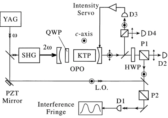
Figure (2-6) is a schematic of our experimental setup for the SPLOPO. We frequency-doubled a diode-pumped cw 1064-nm YAG laser to pump the OPO, which contained a 3 x 3 x 10-mm KTP crystal that was cut for OPO operation at frequency
degen-eracy (crystal cut parameter: 0 = 900, 0 ~_ 23'). The OPO cavity was formed with
a 10-cm-radius input mirror and a 2.5-cm-radius output coupler and had a nominal free spectral range of -1.14 GHz. The input (output) mirror was coated for high transmission (maximum reflection) at 532 nm and maximum reflection (0.75% trans-mission) at 1064 nm. The KTP crystal and the zero-order QWP were antireflection coated at both 532 nm and 1064 nm, and the QWP was aligned nearly normal to the propagation axis. As described in section (2.1.1) co oc sin 24
q, where /q is the
angle between the QWP's fast axis and the crystal's c-axis i2. At V = 0' there was no polarization mixing and we observed that the threshold was approximately the same with or without the QWP. We have also confirmed that at q = 0' we
could continuously tune the OPO through frequency degeneracy without any sign of self-phase locking by varying the crystal's temperature.
Typically, with /q initially set to zero, we tuned the OPO close to frequency
degeneracy with a signal-idler beat note of < 600 MHz that was detected by a
1-GHz InGaAs photodetector, D1. Part of the vertically polarized signal output was monitored by detector D3 and fed back to stabilize the OPO signal intensity at a preset level, while the horizontally polarized idler was monitored by detector D4. The OPO threshold was ~65 mW, although we had both higher and lower thresholds depending on the alignment of the crystal and QWP. The OPO was usually operated at a pump level of 120 mW. Under stable cw operation we set V, to the desired value and tuned the crystal temperature to bring the beat note closer to zero. As the beat frequency came within the capture range, self-phase locking occurred. The capture range was a function of the QWP angle 4
'q and the cavity's free spectral
range. Typical capture ranges were -20 MHz/degree for 4 q up to 4'. We have also
YAG
(OQWP
2w
SHG
PZT
Mirror
Intensity
Servo
D3
c-axis
DD4
P1
KTP
T4WPD2
OPO HWP L.O. P2e
...
Interferenc
Fringe
Figure 2-6: Schematic of the experimental setup. SHG, second-harmonic generator; PZT, piezoelectric transducer. See text for other definitions.
free spectral range.
The signal and idler outputs passed through a half-wave plate (HWP) and then a polarizer P1 for analysis of their frequencies, phases, and polarizations. The hor-izontally polarized, transmitted output of P1 was monitored by detector D2. The vertically polarized, reflected output of P1 was mixed with a local oscillator (LO) that was derived from the YAG laser, and the homodyne signal was detected with the 1-GHz detector, D1. A second polarizer, P2, aligned for transmission of vertically polarized light was placed before D1 to block any leakage of horizontally polarized light from P1.
When the angle Oh between the HWP's fast axis and the crystal's c-axis was set to 0' the idler was transmitted and the reflected light was the intensity-stabilized signal. We monitored the dc portion of the homodyne signal as the LO phase was varied using a piezo-mounted mirror. The ac portion of the Dl output was sent to a rf spectrum analyzer to measure the signal-idler beat note that was obtained when the LO was blocked and OVh ~ 22.50 was set to project the signal and idler onto a
common polarization axis.
Trace (a) in Fig. 2-7 shows a typical LO-signal interference at Oh = 00 (for O4 =
20). We adjusted the LO power to match the signal power of -0.6 mW at D1 (set as
1 arbitrary unit). The interference pattern confirms that the signal and LO had the
same frequency and were phase coherent and hence the OPO was self-phase locked. Trace (b) of Fig. 2-7 shows an interference pattern that indicates that the signal phase
had a ~ 7r phase shift relative to that of trace (a). The switch between traces (a) and (b) in Fig. 2-7 was usually triggered by a momentary perturbation in the OPO operation (without breaking the intensity servo). The two SPLOPO oscillation modes are labelled as p state (preferred state with lower threshold) and n state (non-preferred
state with higher threshold). Traces 2-7(a) and 2-7(b) belonged to the same p state
with the same threshold, sum and difference phases, but they differed by a ir phase
shift in both the signal and idler fields. We observed similar interference and phase
shift between the LO and idler at 4h ~ 45'. We note that the minimum (maximum)
amplitude of the interference does not reach 0 (4) owing to mode mismatch. Trace (c) of Fig. 2-7 is a LO-signal interference for the n state that is phase shifted from trace 2-7(a) by ~67'. The switch between phase states usually occurred after a large perturbation or a break in the intensity servo.
We determined by the following observations that under our experimental
con-ditions the n phase state had a higher threshold (various /h angles): In one set of
measurements with a pre-self-phase locked pump threshold of -40 mW and a pump level of -100 mW, we found that the p state occurred slightly more often than the n state. However, in another set of measurements in which the pump threshold was
-90 mW and the pump level was ~110 mW, we observed the n state only once out of
-100 measurements. This is consistent with theory that predicts a higher threshold for the n state near the center of the operating range.
To characterize the OPO further, we used detector D2 to monitor the transmitted
output of P1. Figure 2-8 shows the Dl and D2 outputs for the (a) p state and
(b) n state at V/h = 1030 and /q = 1'. The angle 'h = 1030 was chosen because
3W
0
-~
0
10
20
30
40
50
LO Sweep Time (ms)
Figure 2-7: LO-signal interference under self-phase locked conditions (/q = 20, Oh =
00) for (a) the p state, (b) the p state with a 7r phase shift in both q1 and
#2,
and (c) the n state.nonzero D2 output for the p state indicates that the output was elliptically polarized.
A comparison of the D1 and D2 outputs for the p and n states in Fig. 2-8 clearly
shows that the two states have different ellipticity. We can therefore obtain the phase difference kd = wi - 992 for each state by varying 'h and analyzing the corresponding
D1 and D2 outputs. We should point out that even though the two states had different
threshold levels the OPO intensity servo always set the signal power level at 1 unit. However, the idler power could vary by as much as 50% which was confirmed by measurements at detector D4.
We made extensive measurements of the p and n states of the SPLOPO as a function of 'Oh, often by maximizing or minimizing the D1 or D2 outputs. For each
D1 or D2 measurement the signal and idler powers were recorded by D3 and D4.
The signal-idler beam walk-off prevented simultaneous mode-matching between the LO and the signal, and between the LO and the idler. We used a numerical fitting program to estimate qd(p) and
#d(n)
for a set of 28 different measurements taken atone PZT scan
(c)
(a)
F

![Figure 2-2: Plot of the minimum threshold [(e2)th] m normalized to K1K2/X2 as a function of the normalized cavity detuning A 1 A 2 /rri1 2 for two different values of co / / 1K2: (a) 0.2, and (b) 0.5.](https://thumb-eu.123doks.com/thumbv2/123doknet/14052931.460403/30.918.189.737.103.525/figure-minimum-threshold-normalized-function-normalized-detuning-different.webp)