Publisher’s version / Version de l'éditeur:
Vous avez des questions? Nous pouvons vous aider. Pour communiquer directement avec un auteur, consultez la première page de la revue dans laquelle son article a été publié afin de trouver ses coordonnées. Si vous n’arrivez pas à les repérer, communiquez avec nous à PublicationsArchive-ArchivesPublications@nrc-cnrc.gc.ca.
Questions? Contact the NRC Publications Archive team at
PublicationsArchive-ArchivesPublications@nrc-cnrc.gc.ca. If you wish to email the authors directly, please see the first page of the publication for their contact information.
https://publications-cnrc.canada.ca/fra/droits
L’accès à ce site Web et l’utilisation de son contenu sont assujettis aux conditions présentées dans le site LISEZ CES CONDITIONS ATTENTIVEMENT AVANT D’UTILISER CE SITE WEB.
Proceedings of the International Thermal Spray Conference 2019, 2019-05-29
READ THESE TERMS AND CONDITIONS CAREFULLY BEFORE USING THIS WEBSITE. https://nrc-publications.canada.ca/eng/copyright
NRC Publications Archive Record / Notice des Archives des publications du CNRC :
https://nrc-publications.canada.ca/eng/view/object/?id=71c25a89-482b-4d3c-b3bb-30606f705db0
https://publications-cnrc.canada.ca/fra/voir/objet/?id=71c25a89-482b-4d3c-b3bb-30606f705db0
NRC Publications Archive
Archives des publications du CNRC
This publication could be one of several versions: author’s original, accepted manuscript or the publisher’s version. / La version de cette publication peut être l’une des suivantes : la version prépublication de l’auteur, la version acceptée du manuscrit ou la version de l’éditeur.
Access and use of this website and the material on it are subject to the Terms and Conditions set forth at
Observation of a redeposition effect while cold spraying Sn-based
mixed powders onto carbon fibre reinforced polymers
Observation of a Redeposition Effect while Cold Spraying Sn-based Mixed Powders onto Carbon Fibre Reinforced Polymers
Mr. Andre Liberati, Dr. Hanqing Che, Prof. Stephen Yue
Mining and Materials Engineering, McGill University, Montreal, QC, Canada Main contact e-mail: andre.liberati@mail.mcgill.ca
Dr. Phuong Vo
National Research Council Canada, Boucherville, QC, Canada
Abstract
Single component tin coatings have successfully been cold-sprayed onto carbon fibre reinforced polymers (CFRPs) in previous studies at McGill University. Coatings with mixed metal powders were also sprayed to improve the coating conductivity for lightning strike protection (LSP) purposes. Results indicated a noticeable improvement in deposition efficiency (DE) related to the addition of a secondary metallic powder (aluminum, copper and zinc); this study is focused on the effect of aluminum. Following cold spray of various Sn/Al mixtures over a wide range of gas pressures, unusual coating morphologies were observed. The study of these morphologies leads to the description of two distinct deposition phases depending on the spray pressure. The presence of submicron particles also supports the occurrence of a powder melting phenomenon during the process.
Introduction
CFRPs are poor electrical conductors – the carbon fibres are approximately 1,000 times more resistive than aluminum to current flow and epoxy resins are 1,000,000 more resistive [1] – so they are prone to damage from lightning strikes that aircraft endure once per year on average [2]. To improve their conductivity while maintaining low densities, “metallizing” or applying metallic coatings to composites such as CFRPs has received increasing interest, but these coatings still suffer from poor quality (porosity, adherence, conductivity, etc.). “Metallization” can be achieved through a series of approaches, such as lay-up molding [3] or arc spray [4], but cold-spray appears as a legitimate alternative [5-9] since it uses relatively low temperatures (several hundred versus several thousand degrees for other techniques), thus limiting the risk of oxidation of the metallic powder particles and the heat damage of the substrate [5].
Coating CFRPs through cold-spray has been tried and mixed results have been obtained regarding the erosion of the soft substrate due to the higher hardness of most metallic powders [7, 10, 11]. Nonetheless, some researchers have encountered success in depositing tin particles on polymeric substrates [6-8] all while recording relatively low deposition efficiencies (DE) (i.e. the ratio of effectively deposited particles on the substrate versus the amount of sprayed particles). In parallel, several researchers have proven that the deposition of a coating on a substrate can be enhanced by mixing ceramic
powders in the feedstock powder, which will produce a shot-peening effect on the relatively softer feedstock powder and produce better coatings [12-14]. Che et al. [15] observed a similar improvement of the coating deposition process when mixing metallic powders (zinc or copper) with tin powders. This improvement was associated with the tamping effect of the secondary component on the relatively softer tin. In a previous study [16], the addition of aluminum to feedstock tin powder was shown to also improve the DE of a pure tin coating but with a different trend from the mixed zinc-tin or copper-tin coatings of [15]; however, only few spray parameters were tested.
In this present study, mixed tin-aluminum powder was cold-sprayed on CFRP and mild steel substrates over a wide range of carrier gas pressures to corroborate and expand on the results of [16]. Tin-aluminum mixed powder with a 90:10 weight ratio was cold-sprayed onto a thermosetting epoxy CFRP substrate at various process conditions with a low-pressure cold spray system. Microanalysis of the coatings was then performed and the deposition mechanism of the mixed powders on CFRPs is discussed. The DE was also measured and a discussion on the variation of the DE is proposed.
Experimental Methods
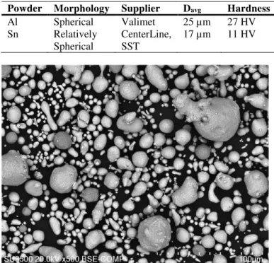
The feedstock materials used in this work are listed in Error! Reference source not found.. The particle sizes of the feedstock powders were measured with a laser scattering particle size analyzer (LA-920, HORIBA, Japan). The tin powder was relatively spherical and had a broad monomodal and non-symmetrical distribution, whereas the aluminum powder, which was also spherical, had a more continuous size distribution with a higher average particle size. The hardness of the aluminum powder was more than double that of the tin powder. Both powders were of commercial purity. The scanning electron microscope (SEM) images of the single component powders are presented in Fig. 1. The powders were mixed in a metallic can without additional media (e.g. milling balls) with a double movement powder mixer for 1h. No significant morphological changes or hardening were noticed in the mixed powder when compared with the starting powders. The compositional back-scattered electron (BSE-COMP) image of the mixed powder is presented in Fig. 2.
The substrates used in this work were CFRPs provided by Bombardier Aerospace (Montreal, Canada) and 1020 mild steel plates. The steel substrates were used as a benchmark to compare the spraying of powders on CFRPs to a typical metal-
Fig. 1: SEM images of the feedstock powders: (a) Sn, (b) Al.
Table 1: Properties of the feedstock powders used in this work Powder Morphology Supplier Davg Hardness
Al Spherical Valimet 25 µm 27 HV Sn Relatively Spherical CenterLine, SST 17 µm 11 HV
Fig. 2: BSE-COMP image of the mixed Sn-10Al powder: Al presents the darker contrast.
metal cold-spraying situation. The CFRP material used here consists of a thermosetting epoxy matrix with continuous carbon fibre reinforcements. The CFRP-panels were made of four plies of 5276-1/G30-500 epoxy carbon prepreg ([0/90]2s). Sheet sections of dimensions 7 x 3 cm were used as substrates during the cold spray campaigns. The substrates were degreased with acetone and the mild steel plates were grit-blasted before cold-spraying. The CFRP substrates were not grit-blasted as it would result in the erosion of the substrate.
The cold spraying was performed at the McGill-NRC cold spray facility at National Research Council Canada in Boucherville. The cold spraying was performed at low pressure with a commercially available CenterLine SST system (Supersonic Spray Technologies, CenterLine Windsor Limited, Canada). This choice enabled the use of the so-called “downstream injection” mode, where the particles were injected in the main gas stream after the throat of the nozzle. The risk of clogging the nozzle when using metals with low melting points, such as tin, was thus reduced. The primary cold spray parameters are listed in Table 2. These parameters were chosen based on previously successful cold-spray campaigns with tin [7, 15]. The carrier gas was nitrogen, the stand-off distance was 18 mm and the gun travel speed was 25 mm/s. The powder feeder rate was set to 1 revolution per minute (RPM), which gave a measured feeding rate of 11.5 g/min. Only one pass was sprayed for each set of conditions, with a step size of 1 mm. Deposition efficiency was measured as the mass gain of the substrate divided by the total mass of feedstock powder fed during the time the gun was over the substrate. Note that previous spraying of single component aluminum on CFRPs generated no deposition because of erosion, whereas pure tin generated a coating with a maximum DE of 20% [7]. After the cold spray process, the samples were observed from a top-surface view then prepared as metallographic samples and characterized with a Hitachi SU3500 Scanning Electron Microscope. The cross-sectional samples were cut and observed parallel to the gun spraying direction, as shown in Fig. 3.
Table 2: Principal cold spray parameters. Powder Carrier Gas
Temperature °C
Gas Pressure psi Sn-10Al 300 50, 55, 60, 70, 80, 100,
120, 150
320 50, 60, 80, 100, 120, 150
Fig. 3: Schematic representation of the different viewpoints for image acquisition
b
a
Results
Figures 4 and 5 respectively show the DE of the mixed powder Sn-10Al on different substrates at 300°C and 320°C as a function of the gas pressure. Coating deposition on steel was achieved for all conditions, while deposition on CFRP was irregular in some cases, namely higher pressures. While the DE on steel provides one maximum for both spray temperatures (around 70 psi), the DE on CFRP seems to provide a local maximum (around 70 psi) then a plateau regime with increasing pressure.
The retention rates of aluminum in the CFRP coatings were measured in the cross-section for several coating conditions (60 psi at 300°C and 60, 80 and 100 psi at 320°C). These rates were estimated by measuring the relative surface areas of tin and aluminum in SEM BSE-COMP images using an image analysis method. From these retention rates, the DE of each pure element in the coating can be calculated with the following expressions:
��=���∗. ��= − ���. �∗
where DE, DEAl and DESn are respectively the overall DE of the
coating, pure Al and pure Sn and rAl is the weight fraction of Al
in the coating. Coating thickness was also measured with these cross-sectional micrographs. The results are listed in Error! Reference source not found.. The retention rates in the coating are very low compared to the initial 10% of aluminum in the powder mix. For the coatings at 60 psi, variations are observed in the overall DE, the DE of pure tin and the thickness of the coating while the retention rates of aluminum remain close to 0%. With increasing pressure at 320°C, the overall DE, the DE of pure tin and the coating thickness decrease while the retention rate of aluminum increases. Nevertheless, the
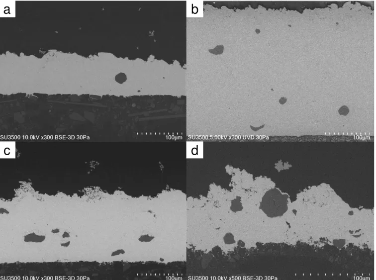
effective DE of pure aluminum remains relatively low (under 20% of the initial aluminum input). The cross-sectional micrographs of the mixed powder coatings sprayed for these conditions are presented in Fig. 6. These coatings are relatively dense with small defects mainly localized around the aluminum particles and only a small number of aluminum particles are noticeable in the coatings, which exemplifies the low retention rates of aluminum. More noticeably, the number of aluminum particles barely increases with increasing pressure at 320°C, while the thickness of the coatings decreases (from 290 to 70 µm) as does the overall DE (from 24% to 6%) and the DE of pure tin (from 27% to 7%). Therefore, there does not seem to be an obvious relation between aluminum retention and overall DE. The area around the top surface is less even with higher pressures as can be seen in Fig. 6 d.
This phenomenon can be better visualized with low-magnification top-surface images of the coatings as seen in Fig. 7. This figure shows an evolution of the coating with increasing pressure while cold-spraying at 300°C. For pressures below 60 psi (Fig. 7 a), a relatively uniform and even surface is obtained. For pressures around 80psi (Fig. 7 b), small agglomerations of powder can be observed and finally, for relatively higher pressures (Fig. 7 c-d), larger dendrite-like protrusions are observable. On another note, the carbon fibre matrix is apparent for very high pressures, as indicated by the white arrow in Fig. 7 d, revealing erosion of the CFRP. The previously described protrusions at higher pressures are also clearly visible to the naked eye as shown in Fig. 8. These protrusions have the same direction as the spray gun as it descends on the CFRP substrate, but they are not noticed on any of the steel substrates. Fig. 8 also reveals a strong difference in deposition throughout the substrate depending on the considered area: in the vicinity of the last spray step, there is no coating on the substrate (the carbon fibre matrix is visible, which is representative of
Fig. 4: Deposition efficiency of Sn-10Al mixed powders sprayed at 300°C on different substrates
Fig. 5: Deposition efficiency of Sn-10Al mixed powders sprayed at 320°C on different substrates
Table 3: Retention rates of aluminum measured at the cross-sections of the CFRP substrates and calculated deposition efficiencies for aluminum and tin in the coating.
Temperature Pressure Volume fraction of Al
Weight fraction of Al
Deposition Efficiency (%) Coating thickness (°C) (psi) (%) (%) Overall Al Sn (µm) 300 60 0.7 0.2 8 ~0 9 90 320 60 0.7 0.3 24 1 27 290 320 80 1.9 0.7 13 1 15 150 320 100 7.6 3.0 6 2 7 70
Fig. 6: SEM images of the cross-sectional microstructures for the Sn-10Al coatings at similar magnifications: (a) 300°C and 60 psi, (b) 320°C and 60 psi, (c) 320°C and 80 psi, (d) 320°C and 100 psi.
erosion) whereas in previously sprayed areas there are the previously discussed protrusions. Below the last spray step, some powder agglomerates can also be noticed. This behavior is representative of all higher pressure cold-sprayed CFRP substrates (above 100psi). The coatings at 320°C follow the same structural evolution with increasing pressure. Aluminum retention in the top surface is quite negligible.
With higher magnification SEM images of these coatings at 300°C (Fig. 9), tin powders can easily be observed for lower pressures (Fig. 9 a). These particles show minimal deformation and sizes ranging from 10 to 20 µm which is relatively similar to the initial feedstock powder (Fig. 1 a). For higher pressures, these particles become less and less discernable. As seen on Fig. 9 b, some larger particles may be observed with intermediate pressures but generally only particles around 5-10 µm are observed on the top surface. With higher pressures (over 100psi), small satellites are observed throughout the top surface and cover the few powders that can be seen, as in Fig. 9 c. At 150psi (Fig. 9 d), these satellites almost completely cover the top surface. Again, the coatings at 320°C follow the same structural evolution with increasing pressure. Higher magnification images of the high-pressure coatings reveal that the small satellites are small tin particles generally smaller than 1 µm, as seen in Fig. 10. As opposed to the feedstock powder
(Fig. 1 a), these particles are spherical and are not representative of the powder distribution results. It is important to note that the detection limit of the Horiba LA-920 is 0.02 µm and in the particle size distribution of the feedstock tin powder, no powders smaller than 1.5 µm are detected.
Discussion
The content of aluminum in the studied coatings is far lower than the initial aluminum input, as noted when studying the retention rates and resulting DE of aluminum in Error! Reference source not found.. An increasing fraction of aluminum was noticeable in the coatings at 320°C, but the DE of aluminum hardly increased and only the tin content in each coating noticeably evolved, which suggests that the evolution of the overall DE is related to the actual deposition of tin and not the aluminum. Therefore, there seems to be no relation between the cold spray conditions and aluminum retention here as already noted in [16]. A thorough study of the steel cross-sections would be interesting to compare the retention of aluminum in the steel coatings. Furthermore, the DE of Sn-10Al at 300°C and 320°C follow a similar trend with increasing pressure as the DE of pure tin on CFRP from [7], but they do not follow the same increasing trend observed in [16]. The maximum DE value of pure tin at 300°C
b
a
Fig. 7: Low magnification SEM top surface images of the Sn-10Al coatings sprayed on the CFRP substrates at 300°C for various pressures: (a) 50 psi, (b) 60 psi, (c) 70 psi, (d) 80 psi, (e) 100psi, (f) 150 psi
(15%) is higher than that of Sn-10Al at 300°C (8%) but lower than that of Sn-10Al at 320°C (25%). These differences could be related to process fluctuations between studies. Further experiments comparing pure tin and mixed metal powders such as tin-aluminum should be conducted to determine the effect of the secondary component with better comparability.
On another note, certain trends seem to stand out when comparing the DE results of this study with the obtained macro- and microstructures. For lower pressures (below 60 psi), the obtained coatings seem to be quite uniform with relatively higher DE and dense, uniform coatings. For intermediate pressures (70-80psi), the coatings tend to be thinner with lower DE and the appearance of small agglomerates on the top surface. For higher pressures (above 100 psi), DE slightly increases then plateaus, but deposition is very inconsistent: two areas clearly stand out from a macroscopic point of view with an area presenting dendrite-like protrusions that follow the same direction as the gun displacement and another area, directly below the last spray step, that presents very poor deposition and exposure of the carbon fibres (relevant of a non-negligible amount of substrate erosion). Furthermore, observation of the CFRP coating cross-sections (Fig. 6) indicates that increasing carrier gas pressure leads to a
decreasing coating thickness. Cross-sections of higher pressure coatings (120, 150 psi) were not observed but, given the top-surface micrographs of the coatings at 150 psi that reveal the carbon fibre matrix, it can be suggested that the average coating thickness would be minimal and only protrusions would provide a measurable thickness – not an actual coating.
Fig. 8: Image of the Sn-10Al coating on a CFRP substrate at 300°C and 150psi. The white arrow corresponds to the last sprayed step in the raster scan.
c
d
Fig. 9: Higher magnification SEM top surface images of the Sn-10Al coatings sprayed on the CFRP substrates at 300°C for various pressures: (a) 50 psi, (b) 60 psi, (c) 70 psi, (d) 80 psi, (e) 120 psi, (f) 150 psi.
Therefore, there seems to be no direct deposition of powders for higher pressures, and the existence of deposited powders under the form of protrusions at these pressures would indicate that a powder redeposition phenomenon must be predominant. The redeposition mechanism is based on powder rebound from the substrate remaining in the gas flow, and then re-accelerated to a velocity in the deposition window.
With regards to coating formation on CFRP substrates, the DE curves could then be separated into two curves as shown in Fig. 11: deposition on the CFRP would take place for pressures below 80 psi (thick line), then the redeposition effect would be observed for higher pressures (dashed line). The existence of two local maxima for the deposition of Sn-10Al on the CFRP substrates could then be explained by these two different phenomena. The absence of an observable redeposition effect on the steel substrates (i.e. no protrusions) would then explain the different behavior for the DE curves of both substrates as described for Fig. 4 and Fig. 5.
Based on the observations made for the top-surface views of the CFRP coatings, it is possible to suggest a mechanism for the redeposition process. Intermediate pressures reveal small agglomerates on the top surface (Fig. 7 b) that seem to be either larger powders or accumulations of smaller powders (Fig. 9 b),
while at higher pressures, sprayed powders do not directly adhere to the substrate (no coating during the last step of the spray gun, as seen in Fig. 8) but they adhere to the previous sprayed steps and give agglomerations or protrusions of particles. For these intermediate and higher pressures, powder velocities must be close to the erosion velocity (upper limit of
Fig. 10: High magnification SE top surface image of the Sn-10Al coatings sprayed on the CFRP substrates at 320°C and 100 psi.
a
b
Fig. 11: Deposition efficiency of Sn-10Al mixed powder sprayed on CFRP at 300°C and 320°C. The continuous line would represent the deposition curve, while the dashed line would represent the redeposition curve.
the deposition window as described by Sturgeon et al. [9]) for there to be erosion. Therefore, either deposition of a small fraction of powders may be observed in the periphery of the main spray area (due to velocities being below the erosion velocity) or a redeposition of the powders with velocities above the erosion velocity takes places. As pressure increases, this redeposition effect would be predominant as there is more erosion, i.e. less powders under the erosion velocity. These powders could rebound from the substrate while remaining in the gas flow, then be accelerated anew to a velocity in the deposition window, hence leading to a possible redeposition of the powders. This phenomenon could explain the deposition of powders or agglomerates of powders as described in Fig. 7 b but does not explain the development of protrusions that seem to grow as the pressure increases. For this phenomenon, a possible sweeping effect could simultaneously be at cause: as the powders impact the substrate, they could be swept laterally by the gas flow (instead of rebounding into the flow), gradually losing velocity and “re-entering” the deposition window to effectively adhere to the deposited agglomerates. This agrees with the idea that the protrusions are oriented in the same direction as the gun displacement direction, since powders swept upwards from the last spray step to a previous spray step would build up on the agglomerates and so the protrusions would build towards the last spray step.
Another possible idea would be related to a splashing phenomenon occurring with partially melted tin powders. The idea of partially melted tin has already been explained by Che et al. [7] as part of the “crack filling” mechanism that makes tin deposition on CFRPs possible and could explain part of the redeposition process. Additionally, the impact of the partially melted tin powder on the CFRP could generate a splashing effect of the molten particle’s outer surface. The resulting droplets could then be swept by the gas flow and be deposited on the agglomerates. Proof of this phenomenon could be seen in the large number of tin particles smaller than 1 µm in higher pressure coatings as seen in Fig. 10 : these particles were not observed in the initial particle size distribution data nor in the SEM images of the powder (Fig. 1 a), whereas they seem quite abundant throughout the top surface of the high pressure coatings. A future study oriented on cold-spraying tin powders with a better controlled size distribution (i.e. minimal content
of powder below 5 µm) is envisioned to determine the precise origin of these particles and their potential correlation with a melting phenomenon.
Conclusion
Mixed Sn-Al powders were cold-sprayed onto CFRP and mild steel substrates with a CenterLine low-pressure cold spray system. Corroborating the results of [16] over a wider range of gas pressures was difficult as the DE trends observed in the present study were different. The addition of aluminum led to better DE than with pure tin at a higher temperature than previously observed, but retention rates of aluminum remained relatively low with the coatings being mainly composed of tin, as previously noted. Spraying at higher pressures led to noticing unusual surface structures on the CFRP substrates and a redeposition phenomenon was described. Even though of no actual interest with regards to substrate coating, the microstructure of the observed protrusions reveals the existence of submicron tin particles seemingly inexistent in the initial feedstock powder. These particles could be proof of a melting phenomenon described in previous studies and will be studied in future works.
Acknowledgment
The authors wish to acknowledge the financial support of the Natural Sciences and Engineering Research Council of Canada (NSERC) through the Green-SEAM strategic network and the McGill Engineering Doctoral Award (MEDA). The industrial partner, Bombardier Aerospace, is gratefully acknowledged. Mr. Marco Zeman from National Research Council Canada, Boucherville, is acknowledged for his contribution to the cold spray experiments.
References
1. US Department of Transportation: F.A.A.,
Handbook-Airframe, Aviation Maintenance Technician,
(Oklahoma City, 2012), Vol. 1, p.7-6.
2. A. Larsson, A. Delannoy, and P. Lalande, “Voltage drop along a lightning channel during strikes to aircraft”, Atmospheric Research, Vol. 76, No. 1-4 (2005), pp. 377-385.
3. G. Archambault, et al., “Metallization of carbon fiber reinforced polymer composite by cold spray and lay-up molding processes”, Surface and Coatings
Technology, Vol. 300 (2016), pp. 78-86.
4. R. Wang, et al., “Effect of arc spraying power on the microstructure and mechanical properties of Zn–Al coating deposited onto carbon fiber reinforced epoxy composites”, Applied Surface Science, Vol. 257, No. 1 (2010), pp. 203-209.
5. J. Affi, et al., “Fabrication of Aluminum Coating onto CFRP Substrate by Cold Spray”, Materials
Transactions, Vol. 52, No. 9 (2011), pp. 1759-1763.
6. H. Che, et al., “Metallization of Various Polymers by Cold Spray”, Journal of Thermal Spray Technology, Vol. 27 No.1-2 (2017), pp. 169-178.
7. H. Che, P. Vo, and S. Yue, “Metallization of carbon fibre reinforced polymers by cold spray”, Surface and
Coatings Technology, Vol. 313 (2017), pp. 236-247.
8. R. Lupoi and W. O'Neill, “Deposition of metallic coatings on polymer surfaces using cold spray”,
Surface and Coatings Technology, Vol. 205, No. 7
(2010), pp. 2167-2173.
9. A. Sturgeon, et al., “Cold Sprayed Coatings for Polymer Composite Substrate”, Proc 10th Int’l
Symposium on Materials in a Space Environment & 8thInt’l Symposium on Protection of Materials and
Structures in a Space Environment, Collioure, France,
June 2006.
10. A. Ganesan, M. Yamada, and M. Fukumoto, “The Effect of CFRP Surface Treatment on the Splat Morphology and Coating Adhesion Strength”, Journal
of Thermal Spray Technology, Vol. 23, No. 1-2
(2013), pp. 236-244.
11. D. Zhang, P.H. Shipway, and D.G. McCartney, “Cold Gas Dynamic Spraying of Aluminum: The Role of Substrate Characteristics in Deposit Formation”,
Journal of Thermal Spray Technology, Vol. 14, No. 1
(2005), pp. 109-116.
12. H.Y. Lee, et al., “Cold Spray of SiC and Al2O3 With
Soft Metal Incorporation: A Technical Contribution”,
Journal of Thermal Spray Technology, Vol. 13, No. 2
(2004), pp. 184-189.
13. E. Irissou, et al., “Investigation of Al-Al2O3 Cold
Spray Coating Formation and Properties”, Journal of
Thermal Spray Technology, Vol. 16, No. 5-6 (2007),
pp. 661-668.
14. H. Koivuluoto and P. Vuoristo, “Effect of Powder Type and Composition on Structure and Mechanical Properties of Cu + Al2O3 Coatings Prepared by using
Low-Pressure Cold Spray Process”, Journal of
Thermal Spray Technology, Vol. 19, No. 5 (2010), pp.
1081-1092.
15. H. Che, et al., “Cold spray of mixed metal powders on carbon fibre reinforced polymers”, Surface and
Coatings Technology, Vol. 329 (2017), pp. 232-243.
16. A. Liberati,.et al., “Cold Spraying of Mixed Sn-Al Powders onto Carbon Fibre Reinforced Polymers”,
Proc Int’l Thermal Spray Conference, Orlando, FL,