Prof. E. A. Guillemin
N. DeClaris
M. S. Macrakis
Prof. R. E. Scott Y. C. Ho T. E. Stern
F. F. Lee
A.
INTRODUCTION
The Analog Computer group is engaged in a number of basic investigations in the
field of analog and special-purpose computers.
The emphasis has been on the
under-lying concepts and the introduction of new components rather than on the design,
con-struction, or operation of a large computing facility.
We are primarily concerned with analog computers, rather than digital computers,
because more basic research seems to be needed in the analog field. There is great
need for an increase in the speed and the accuracy of analog equipment.
While some combined analog-digital equipment has been constructed, the emphasis
is on special-purpose computers.
The underlying philosophy of special-purpose
com-puters is that they are cheap enough and simple enough to be used by the person who has
the problem to be solved.
They do not interpose the extra link of a large, trained
operating staff between the problem and its ultimate solution.
Since a great many of the special-purpose computers that have been built are directly
or indirectly related to network theory, our group has maintained an active interest in
network theory and has done some work in this field.
At the present time the research falls into three groups: (a) those problems relating
to computer systems and the basic philosophy of computers, (b) the design of new
com-puting elements, and (c) applications of modern network theory.
R. E. Scott
B.
COMPUTER SYSTEMS
1.
Energy and Power in Nonlinear Systems
A basic investigation is being conducted into energy and power relations in nonlinear
systems, such as those involved in computers. This investigation begins with a
transi-tional stability study of second-order systems.
In the design of electromechanical multipliers and function generators, various
schemes have been employed to extend their dynamic range. Among other things,
satu-ration at high-power level represents a limitation to such efforts. This limitation is
similarly encountered in the related field of feedback control systems. The
electro-mechanical device, which is stable in the linear sense, may exhibit relative instability
when saturation occurs.
Such operation involves the transition between linear and
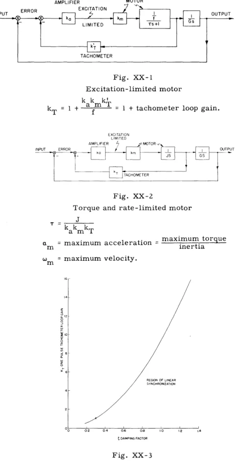
non-linear modes. A phase-plane study has been made of the transitional stability of two
second-order electromechanical systems (Figs. XX-i, XX-2) that are frequently used
to form multipliers and function generators.
AMPI IFIFP
Fig. XX-1
Excitation-limited motor
k k mk
kT =+ f 1
+
tachometer loop gain.
Fig. XX-2
Torque and rate-limited motor J T k kmk T
am T
a = maximum acceleration = mm
maximum torque
inertia
= maximum velocity. REGION OF LINEAR SYNCHRONIZATION 0 02 0.4 0.6 0.8 10 1.2 1.4 t DAMPING FACTORFig. XX-3
Transitional behavior of the system shown in Fig.
XX-1.
rPUT MOTOR
14 12 I0 8 CU C REGION OF LINEAR SYNCHRONIZATION 0 02 04 06 08 t DAMPING FACTOR Transitional behavior Fig. XX-4
of the system
shown in Fig. XX-2.
The result for the system of Fig. XX-1 is shown in Fig. XX-3. The system is said to be linearly synchronized if the response to a step input of very large amplitude
remains linear once it has left the saturated region. The result obtained by W. Hurewicz and N. B. Nichols (Servos with Torque Saturation: Part 1, Rad. Lab. Report 555, May
1944) is indicated by a cross on the curve. The result for the system of Fig. XX-2 is shown in Fig. XX-4. A formula for the approximate number of nonlinear entries when the number n is large, is given by
1 m
n< <n+1 2 a T
85
m
F. F. Lee
2. Investigations and Applications of the Theory of Signal Flow Graphs to Analog Computers
An attempt has been made to indicate to what extent computer component errors (especially of a dynamic nature) affect the form of the equations of the original physical problem being solved. Instead of expressing the resultant computer errors as actual functions of the independent variable, the errors are expressed as modifications of the original differential equations.
Thus far, we have determined the theoretical limit on the number of dynamic com-ponents necessary to solve a system of simultaneous linear constant coefficient equations
10 12 I
(XX. ANALOG COMPUTER RESEARCH)
on a computer. A systematic method of proceeding from the original equations to the final optimum computer connection is in the process of being completed.
Given a set in the form
L x 1+ L2X2 + ... + Lln x = S
Ln1 LnZX2 nn n 1n
L x +L x+ ... + L x = S
where L is a linear operator (that is, a polynomial in s), and S is a known function
pq q
of the independent variable, a signal flow graph is drawn representing the relations as they are written above, that is, with the unknown functions as sources and the known functions as sinks. The graph then consists of open paths, each path being a single branch. To make this system physically realizable on a computer we must invert at least n paths. The manner in which these paths are to be chosen depends largely upon the characteristics of the computer being used. We shall assume that we are dealing with a computer containing only integrators as dynamic elements. To utilize the
inver-sions to the best advantage, only n paths of inversion will be chosen. These paths inter-cept all 2n nodes, that is, no two paths of inversion will interinter-cept the same node. They are also chosen so that the product of their branch transmissions is as large as possible, to reduce the order of each individual branch operator. If paths of inversion other than those specified above are used, the resultant flow graph will present difficulties in physical realization. However, these difficulties can usually be overcome by performing appropriate loop inversions until the configuration reverts to the one that would have resulted from the correct initial choice of open path inversions.
The theoretical minimum number of integrators necessary to solve a given set of equations is equal to the order of the determinant of the operational coefficients. This is always either equal to, or less than, the sum of the orders of the highest derivatives of all the dependent variables. Therefore, the next step in the procedure is to determine this minimum and compare it with the number of integrations present in the inverted flow graph. If they are equal, no further advantage in this direction may be obtained by more modifications. If they are not equal, the number of integrators can usually be reduced to the minimum by such manipulations as the introduction of additional nodes, and the like. These further modifications, which do not change the fundamental relations between the variables, may also be necessary in certain cases for reducing the order of some branch transmissions that may still not be realizable on the computer even after the best possible combination of branch inversions. These modifications should also be used to make as many of the transmissions negative as possible, since electronic com-puter components always have an inherent phase inversion.
This method has been tried on several examples and seems to have some advantages over the conventional methods of setting up the computer.
Additional investigation is to be performed on modification of the flow-graph con-figurations to reduce the sensitivity of the solutions to errors in branch transmis-sions.
T. E. Stern
C. COMPUTER ELEMENTS
1. Square-Law Network
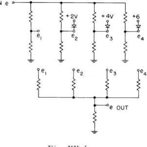
Two networks, shown in Figs. XX-5 and XX-6, were constructed and tested during the past months. Initial tests showed that the network in Fig. XX-5 is superior to that of Fig. XX-6 in both stability and accuracy.
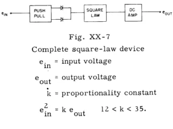
A push-pull stage was then constructed for the second network to enable it to accept
both plus and minus signals. At present, the device can be represented by Fig. XX-7. This device uses four straight-line segments to approximate the square-law charac-teristics. It has about 1 percent static accuracy. With ac signals the accuracy drops to 10. 5 percent due to an equal gain in the push-pull stages. Frequency response is unknown at the present time because many potentiometers have been used in the circuit to faciliate experimental adjustments and they decrease the upper frequency range. At present we need a more stable push-pull driving stage that has a maximum output of 3 ma into a 10-kilohm load and a better switching arrangement for the diodes in the net-work. IN e +2V +4V +6 e2 2 e34 e DC e OUT AMP
le
OUT Fig. XX-5Square-law network using active elements.
Fig. XX-6
Square-law network using
passive elements only.
Rf(XX. ANALOG COMPUTER RESEARCH)
PUSH SQUARE DC
eIN PULL LAW AMP OUT
Fig. XX-7
Complete square-law device
e.
= input voltage
1n
eout = output voltage
k= proportionality constant
ein = ke
12 < k < 35.
in
out
The principal limitation of square-law devices with germanium diodes is the finite
forward and backward resistance.
It is safe to say that unless elaborate compensation
is used an accuracy of 0. 5 percent is the practical upper limit for a square-law device
of this nature.
Any attempt to go above the limit will sacrifice the simplicity of the
net-work.
Y. C. Ho
2.
Delay Lines
The delay lines and their associated equipment built by Dr. C. A. Stutt are being
repaired and put into operation for experimental investigations of Dr. M. V. Cerrillo's
theory of network synthesis in the time domain.
Y. C. Ho
D.
APPLIED NETWORK THEORY
1. Potential Analogs
During the preparation of a technical report from the work on potential analogs the
material has been completely revised. It is true that an equation such as Eq. 2
(Quarterly Progress Report, July 15, 1953, p. 101) is quite costly to deal with, and for
this reason more examples have not been worked out. In the revised material the main
ideas and results remain the same but they are presented in a more precise and
satis-factory form.
M. S. Macrakis
2.
RC Filter Frequency Transformations
In the techniques of modern network synthesis it is customary to satisfy the
require-ments for a desired filter on a normalized lowpass prototype and then, through a
frequency transformation, to obtain the correct type of filter, highpass, or bandpass.
It is the purpose of this study to investigate the applicability of frequency transformation
in the case of a transfer function of RC character.
a.
Lowpass to highpass transformation
Consider a transfer function Z
1 2(s) which satisfies all the RC requirements
h
(s
2+
A.s
B
i ) Z12(s ) = C i=1 mr (s + ci)
i=1
n
- (s + Pi)(S + i)(s + a )
i=lwhere n = 2m as the upper limit and a. is real and positive.
1
To make the lowpass-to-highpass transformation let s - k/s. The new transfer function is
n
S(k
+ pis)(k + Pis ) i=lZ
z(s) = Z1L2
2 C, n = 2m (k + a.s)1
nsP
1
(k +
i:1
m11
(k
Pis)(k + Pis)
C, 2m = n + p + ais) 1sP
(s
+ k/i)(s
+
k/P
i ) i=1(s + k/ai)
]
i 2 Ci=m
ni
a
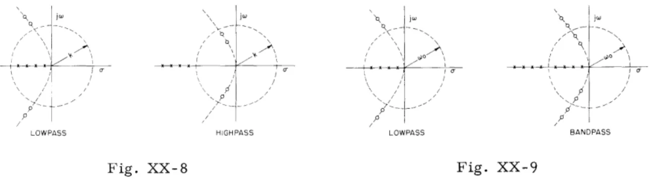
i=1On examining this equation it is seen that the poles and zeros of the new function are inverted about a circle of radius k. (See Fig. XX-8.) Since the RC character of the transfer function is preserved, that is, all poles are simple and on the real axis, and n
4
2m, the transformation is still applicable.b. Lowpass to bandpass transformation
For this type of frequency transformation let
sk s
(-Yo
(XX. ANALOG COMPUTER RESEARCH) j q t / \1 \ / p p / A
LOWPSS HIGHPASS LOWPASS BANDPASS
Fig. XX-8
Fig. XX-9
where wo is the center frequency desired, and k is a bandwidth factor. width product is constant.
We observe that the poles of the new transfer function
The gain
band-sW s
will be solely determined by the transformation of the factor
(s+ 0i) - s 2
1 W 0S(
o 2
Sa.k s+w i
k
0oHowever, since the degree of the numerator is smaller than or equal to the degree of the denominator it is sufficient to consider only the factor
(
2
W O + ..
i T
s +
W
= (s+y)(s+6)
The necessary condition for y and 6 to be positive is
2 2
-L. W Ia.o 1- 1 o 2k - 2 +4 k 2 2 iLo 2 1/2 2 a. 1 k>1 2kSince k determines the bandwidth, it is clear that there is a low limit in the bandwidth
& =
of the bandpass network. This limit is determined by the pole a.i which is closest to the1
\ i
Z(B)s) = z
12 " 12
Fig. XX-10
origin in the lowpass structure.
This constitutes the only restriction on the transfor-mation from a lowpass RC structure to another bandpass. It is obvious that forZ1 2(0) = z2
s
=
+j 0
,therefore wo is the center frequency and for
Z 2 (
+j) = z (B)
s
= +
+
-k - o z2k/
Hence the bandwidth AW is
I1
AW =
o
k
The minimum Q of the RC network therefore becomes
AW
1 Cmink- 2
If the roots of the equation are examined it is seen 2 C1 L 2k 2k 2 o
or
2y- 6
=
oTherefore yi and 6i constitute inverse pairs about the periphery of a circle from the W
(XX. ANALOG COMPUTER RESEARCH)
origin with radius ow (See Fig. XX-9.)
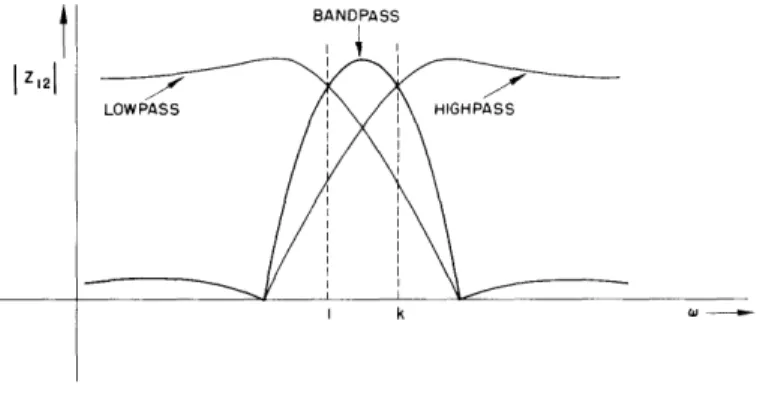
From Fig. XX-9 the following relation
Z1 (s) = Z12(s) Z Z(s)
is obvious for the case of o
=k = 1. This suggests an alternative procedure of
super-imposing the magnitude characteristic of a lowpass and a properly derived highpass
filter as in Fig.
XX-10.
N. DeClaris
3.
Duality of Ideal Transformers
Given an electrical circuit containing R's, L's, C's, and sources, there is a
tech-nique that enables one to interchange voltage with current and junction points with
meshes by merely topological considerations.
The following theorem extends the
appli-cation of this technique to circuits containing ideal transformers.
The significance of
the theorem is obvious, since one has to recognize the fact that ideal transformers are
very frequently used in circuit analysis.
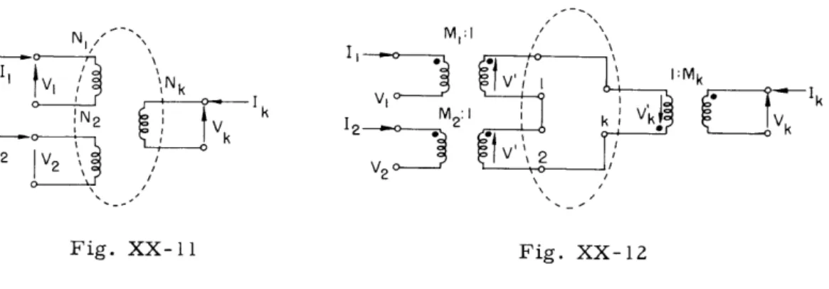
Theorem: The dual of an n-winding ideal transformer with Nk turns in each winding
consists of n two-winding ideal transformers of 1:N
kturns ratio each, and with the
secondary windings connected in series; the secondary voltages are taken in the same
clockwise (or counterclockwise) direction.
Proof: Consider an ideal transformer with n-windings.
(See Fig. XX-11ii.)
Each
of the windings has N
knumber of turns.
Let the voltage polarities and current flow
directions be assumed to be those shown in Fig. XX- 11.
Since the system is lossless,
the instantaneous power is zero.
n
SVkIk = 0
(1)
k=0
Furthermore, by definition
V
1V
2V
k1
=constant
(2) N1 N2 NkDivide Eq. 1 by Eq. 2.
n V
Z
V
k0
k
Vk
k=
k=0Since
N - = constantVk
nZ
NkIk = 0
(3)
k=0
*Mk
E ,0-k
Fig. XX-11
In order to obtain this dual set Thus we have
I'
N1
Fig. XX-12
of equations, it is sufficient to interchange Ik and Vk.
2 k
N
N
- constant N2 Nk n NkVk = 0(4)
(5)
Obviously the power equation has not been altered
n
Z
Vk
k= 0
k=0
Therefore the system defined by Eqs. 4 and 5 constitutes the dual of the circuit shown
in Fig. XX-12.
In order to recognize the system more easily, let
1
Nk
M
kEquations 4 and 5 are rewritten as
MII = M2 = MkIk = constant
nVk
Z0 k
k=0
(6)
(7)
The circuit of Fig. XX-12 corresponds to Eqs. 6 and 7, as can be easily verified. For a general orientation on this topic the reader is referred to E. A. Guillemin, Communication Networks, Vol. II, chap. V, John Wiley and Sons, Inc., New York,
1935 and E. C. Cherry, "The Duality Between Interlinked Electric and Magnetic Circuits and the Formation of Transformer Equivalent Circuits," Proc. Phys. Soc. (London) B 62, 101, 1949. N. DeClaris N N2 2 2 1 LV2 J Nk Ad I I