Coding and Scheduling Optimization over Packet
Erasure Broadcast Channels
by
Weifei Zeng
BASc., University of Toronto (2009)
Submitted to the Department of Electrical Engineering and Computer
Science
in partial fulfillment of the requirements for the degree of
Master of Science in Electrical Engineering and Computer Science
at the
MASSACHUSETTS INSTITUTE OF TECHNOLOGY
MASSACHUSETTS INSTITUTE
OF TECHNLo'CG-Y
MAR
2 0 2012
February 2012
@
Massachusetts Institute of Technology 2012. All rights reserved.
Author... ...
I...
Department of Electrical Engileering and Computer Science
February 1st, 2012
C ertified by ...
:.. ..
...
Muriel Medard
Professor of Elec. Eng
Thesis Supervisor
A ccepted by ...
..
.
e...
..
k
Les -e'A. Kolodziejski
Chairman, Department Committee on Graduate Theses
Coding and Scheduling Optimization over Packet Erasure
Broadcast Channels
by
Weifei Zeng
Submitted to the Department of Electrical Engineering and Computer Science on February 1st, 2012, in partial fulfillment of the
requirements for the degree of
Master of Science in Electrical Engineering and Computer Science
Abstract
Throughput and per-packet delay can present strong trade-offs that are important in the cases of delay sensitive applications. In this thesis, we investigate such trade-offs using a random linear network coding scheme for one or more receivers in single hop wireless packet erasure broadcast channels. We capture the delay sensitivities across different types of network applications using a class of delay metrics based on the norms of packet arrival times. With these delay metrics, we establish a unified framework to characterize the rate and delay requirements of applications and optimize system parameters. In the single receiver case, we demonstrate the trade-off between average packet delay, which we view as the inverse of throughput, and maximum ordered inter-arrival delay for various system parameters. For a single broadcast channel with multiple receivers having different delay constraints and feedback delays, we jointly optimize the coding parameters and time-division scheduling parameters at the transmitters. We formulate the optimization problem as a Generalized Geometric Program (GGP). This approach allows the transmitters to adjust adaptively the coding and scheduling parameters for efficient allocation of network resources under varying delay constraints. In the case where the receivers are served by multiple non-interfering wireless broadcast channels, the same optimization problem is formulated as a Signomial Program, which is NP-hard in general. We provide approximation methods using successive formulation of geometric programs and show the convergence of approximations. Practical issues of implementing proposed coding and optimization scheme on existing layered network architecture are also discussed.
Thesis Supervisor: Muriel Medard Title: Professor of Elec. Eng
We gratefully acknowledge the funding support from the Air Force Office of Scientific Research (AFOSR) under award No. 016974-002, from France Telecom S.A. under award number: 018499-00 and from BAE Systems National Security Solutions, Inc, under award number: 739532-SLIN 0002.
Acknowledgments
Foremost, I owe my deepest gratitude to my supervisor, Prof. Muriel Medard. This thesis would not have been possible without her support the last two years. Her extraordinary pa-tience and understanding, insightful guidance and mentoring have helped me tremendously. I feel really fortunate to work in the Network Coding and Reliable Communication Group.
Besides my supervisor, I am really grateful to Dr. Chris Ng at Bell Labs, for this insightful comments and helpful feedback on major parts of the work. My sincere thanks also goes to Prof. Catherine Rosenberg at the University of Waterloo and Dr. Laurent Massoulie at Technicolor Paris Research Lab for inspiring discussions during my visits and internship. I would also like to send my gratitude to Prof. Frank Kschischang and Prof. Baochun Li, at the University of Toronto, for guiding me into the field of communications and enlightening me with the first glance of research with so much patience and enthusiasm.
I would also like to thank my friends and colleagues in my office, the NCRC group
and in the EECS department. In particular, I would like to thank Flivio du Pin Calmon, Arman Rezaee, Jason Cloud, Matt Carey and Georgios Angelopoulos for many interesting discussions and memories throughout the last two years. My thanks also goes to Soheil Feizi, Ali Parendeh-Gheibi, Danail Traskov and Viveck Cadambe, for many inspiring discussions on various exciting topics and problems.
Last, and most importantly, I would like to thank my parents. I could not have come this far without the unwavering love and support from them.
Contents
1 Introduction
1.1 Background and Motivation . . . . 1.2 Thesis Outline and Main Contributions . . . . .
1.3 Related W orks . . . . 1.4 Thesis Organization . . . .
2 Preliminaries, Models and Metrics
2.1 Network Coding . . . . 2.1.1 Butterfly graph . . . . 2.1.2 Intra-session vs inter-session coding . . .
2.2 Coding Schemes and Delay Metrics . . . . 2.2.1 Fixed generation-based Coding Scheme . 2.2.2 Adaptive Linear Coding Scheme . . . . .
2.2.3 E,-Norm Delay Metrics . . . . 2.2.4 Delay In Adaptive Coding Scheme . . . 2.3 Geometric Programming . . . .
3 Joint Coding and Scheduling Optimization with Varying Metrics 3.1 Single Broadcast Channel With Packet Erasures . . . .
3.1.1 System M odel . . . .
3.1.2 Delay Optimization.... . . . . . .. 3.1.3 Delay Constrained Optimization with GP . . . .
23 . . . . 23 . . . . 24 . . . . 24 . . . . 26 . . . . 27 . . . . 29 . . . . 31 . . . . 33 . . . . 35 39 39 40 42 46
3.1.4 Illustrations of trade-offs and advantages . . . . 48
3.2 Multiple Non-interfering Wireless Packet Erasure Channels . . . . 52
3.2.1 Signomial Program Formulation . . . . 54
3.2.2 Successive GP Approximation. . . . .. 55
3.2.3 Convergence . . . . 58
4 Inter-Session Coding in Short Feedback Delay Settings 63 4.1 Model and Assumptions . . . . 63
4.1.1 An Exam ple . . . . 65
4.2 Outer bound on the capacity of packet erasure broadcast channels . . . . 65
4.3 Pair-wise Opportunistic Coding . . . . 68
4.3.1 Coding M ethod . . . . 68
4.3.2 Markov Model For Two Receivers . . . . 68
4.3.3 Steady-state Distribution . . . . 71
4.3.4 M Receivers... . . . . . . . 76
5 Architecture and Protocols 79 5.1 Session Definition . . . . 79
5.2 Packet Transmissions and Acknowledgements . . . . 82
5.2.1 Encoded Transmissions . . . . 82
5.2.2 Acknowledgement and Retransmission . . . . 85
6 Conclusions and Future Work 87
List of Figures
1-1 Home network and various networking applications . . . . 16
(a) An example of modern home network: various devices and applications share the same wireless channel from a single access point . . . . 16
(b) Cisco Visual Networking Index (Feb 2011): A simple categorization and prediction of Internet data traffic trends shows fast increasing of delay sensitive traffice such as media streaming . . . . 16
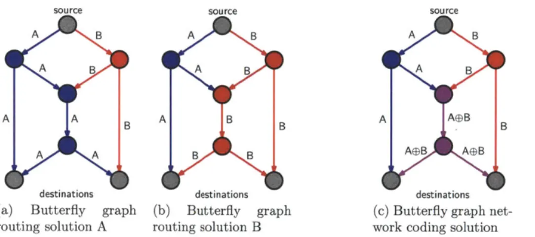
2-1 Comparison between routing and network coding for multicast on the butterfly graph. The source looks to transmit A and B to both destinations: Routing in (a) and (b) forces central edge to transmit original packet, resulting 1.5 average throughput. Network coding in (c) achieves min-cut capacity of 2 for both destinations. . . . . 25
(a) Butterfly graph routing solution A . . . . 25
(b) Butterfly graph routing solution B . . . . 25
(c) Butterfly graph network coding solution . . . . 25
2-2 A inter-session coding example of the butterfly graph: Source si transmits A to sink ti, while s2 transmit
B
to t2. . . . . 262-3 Adaptive linear network coding based transmission model: For the packet flow
f,
the transmitter (Tx) maintains a coding bucket Gf, whose size is adaptively determined based on the delay constraints at the receivers. . . . . 272-4 A session with varying coding bucket size. The initial coding bucket size is 3, containing packets {Pi, P2, P3}. After finishing the three packets, the receiver
decide to shrink the bucket size to 2, containing packets {P5, P6}. . . . . 29 2-5 An illustration of encoding: the encoded packet P[t] is the linear combination
of all packet in the coding bucket with coefficients ak[t] chosen randomly from som e finite field. . . . . 30
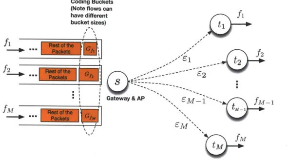
3-1 System model with single transmitter s and M receivers {t, . .. , tM}. Flow
fi
is requested by ti, while Gf, represents the coding bucket for flow fi. . . . 413-2 Tradeoff of d(1) vs d(oo) with varying feedback delay D. The shaded region
represents all the achievable delay pair (d(1), d(oo)). Moving from left to right on the optimal trade-off curve for fixed D, we are decreasing bucket size K and increasing the delay sensitivity p. . . . . 49
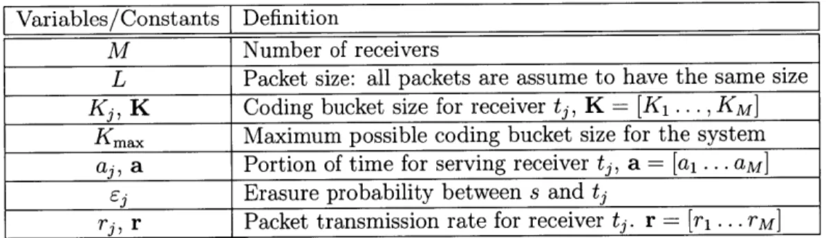
3-3 Min rate vs delay sensitivity pi of different coding methods for an example
sys-tem with 5 receivers, D = 5, L 1 and erasures e = [0.4,0.1,0.15,0.2,0.25]. In the case of K = 100 and K 25, the min rate drops considerably beyond
certain threshold pi, and the optimization is infeasible before p1 = 2.9, while with the adaptive scheme, the min rate drops much less as pi increases. . . . 50
3-4 Coding bucket size vs delay Sensitivity pi of different coding methods for an example system with 5 receivers. D = 5, L = 1 and erasures e =
[0.4, 0.1, 0.15, 0.2, 0.25]. The adaptive scheme reduces the coding bucket size
accordingly, as delay sensitivity increases, to meet the delay constraints. . . . 51
3-5 a1 vs Delay Sensitivity pi of different coding methods for an example system
with 5 receivers. D = 5, L = 1 and erasures e = [0.4, 0.1, 0.15, 0.2, 0.25].
In fixed generation size schemes, the service time a1 has to rapid increase
in compensation for large generation size to meet the increasing tight delay constraints, while service time ai remains relatively constant for the adaptive schem e. . . . . 52
3-6 An example system with 2 senders and 4 receivers. The broadcast channels
associated with si and s2 do not interfere, while all receivers are connected to
both channels simultaneously. . . . . 53
3-7 Convergence of maximum min rate in the example system, as the number of
it-erations increases. p = [1.6 1.7 1.8], D = 5, L = 1,e = [0.2 0.1 0.15; 0.15; 0.2 0.25] 58
3-8 Convergence of bucket sizes in the example system as the number of
iter-ations increases. Note that the bucket size variation is very quite small.
p = [1.6 1.7 1.8], D = 5, L = 1, e = [0.2 0.1 0.15; 0.15; 0.2 0.25] . . . . 60 3-9 Convergence of scheduling coefficients the example system as the number of
it-erations increases. p = [1.6 1.7 1.8], D = 5, L = 1, e = [0.2 0.1 0.15; 0.15; 0.2 0.25]
61
4-1 A packet erasure broadcast channel with 2 receivers . . . . 64
4-2 Markov chain for pair-wise inter-session coding based on erasure patterns . . 69
4-3 Cuts at the right part of the finite state Markov chain. A = B - 1, C = B -2,
where B is the buffer size. . . . . 72
5-1 Network Coding sublayer design: the sublayer is inserted directly above net-work layer and a session at this sublayer includes all IP packets from the gateway, destined to the same receiver. . . . . 81
List of Tables
3.1 Summary of variables, constants and terms for the single broadcast channel case . . . .. - - - . - . . 47 4.1 Transmission of packets in the first few time slots: "/" indicates successfully
Chapter 1
Introduction
1.1
Background and Motivation
The growing diversity of network applications, protocols and architectures makes it increas-ingly challenging to understand and to measure the needs of various applications in terms of delay and rate for desired Quality of User Experience (QoE). One of the typical scenarios happens in the case of modern home network environment (Figure 1-la), where multiple networking devices are usually connected with the same wireless broadcast channels associ-ated with one or more WiFi access points (AP). The network is shared by a wide variety of applications, such as media streaming to media players, file downloading at PCs, online gaming traffic on gaming consoles and real time voice or video traffic from VoIP devices (Fig-ure 1-1b). While there is great heterogeneity of network applications, the service pattern or the transmission strategies used in today's networking device are largely based on simple prioritization models that may be inefficient. Fundamental trade-offs between throughput and delay in most communications systems increases the importance of capturing precisely the delay-throughput requirements and constraints of applications in order for systems to
allocate resources efficiently and to enhance QoE.
In many of the communication systems, the trade-off between rate and delay is most evident in the choice of coding methods and coding block sizes. Generally, a large coding
pointM00 omoi
(r4
(a) An example of modern home network:various devices and applications share the same wireless channel from a single access point
Eabytes per Month
60 C VO St tinOnline Gaming s W s Datr 24% 0 File Shaving 30 U Internet Vieo
03-111,
1%
2010 2011 2012 2013 2014 2015(b) Cisco Visual Networking Index (Feb 2011): A simple categorization and prediction of Internet data traffic trends shows fast increasing of delay sensitive traffice such as media streaming
Figure 1-1: Home network and various networking applications
block does not only make systems more resilient to channel variations and erasures, but also provides higher throughput. As a trade-off, large coding block size usually introduces longer decoding delay, as the receivers need to collect longer coding blocks before decoding. They may also suffer longer computational delay because of the increased decoding complexity as-sociated with longer coding blocks. The tolerable decoding delay durations vary drastically depending on a series of factors, such as channel and network statistics. But predominantly, the tolerable delay is limited by application's QoE requirements. For instance, applications like file downloading or FTP protocols aim solely to maximize the average transmission rate, thus minimizing the overall completion time. Since non-integral file parts provide no utility for users, such downloading protocols are not concerned with the inter-delivery times between consecutive packets. On the other hand, applications such as real-time video conferencing are highly sensitive to delay of any consecutive packets. Failure to meet continuous delivery deadlines in stream of packets quickly deteriorates QoE. However, the two extremes in delay sensitivities by no means represent all types of networking applications today. Progressive downloading video, for example, would be more delay sensitive than file downloading, as the video player has to catch up with certainly playback deadline for sequenced video content or packets. On the other hand, its delay sensitivity is usually not as high as a live video conference, since in a non-real time scenario, a receiver is usually allowed to buffer sufficient
content before playback starts or whenever the playback is to be resumed after some inter-ruptions. Therefore, a range of sensitivity, instead of two extremes, is a better reflection of common applications. Furthermore, at different stage of a transmission session, variations of delay sensitivity maybe observed for the same application, as in the case of progressive video downloading, depending on the amount of sequentially buffered content.
The proliferation of low cost gateways with fast-increasing computation capability does not only bring more flexibility in packet coding options, but also provides the possibility to optimize the efficiency of network resource allocation based on coding methods and the rate-delay requirements of different applications. In this thesis, motivated by the typical home network scenario, we focus the problems in the scope of single hop wireless broadcast channel with packet erasures. We explore the possibility of applying linear network coding between the senders and receivers in such systems, from a perspective of designing and optimizing coding and scheduling parameters different delay sensitivities in the existence of delay-rate trade-offs. We investigate how properly designed and optimized coding and scheduling would allow the system to accommodate better the delay and rate requirements of various applications.
1.2
Thesis Outline and Main Contributions
The thesis starts by developing a unified framework to study rate and delay trade-off of packet based linear block coding schemes. We use a class of delay metrics based on the f,-norms of the packet inter-arrival times to represent delay-rate characteristics and require-ments of applications. At one extreme of the p values, the class of delay metrics could capture the average packet delay and therefore the average rate of transmission. At the other extreme of the p values , the metrics measure the maximum ordered inter-arrival de-lay. We apply the metrics to linear intra-session network coding in our system and express the delay cost function in terms of coding parameter and system parameters. With these delay cost measures, we establish methods to optimize coding and scheduling parameters in the networking system, where various devices with different delay requirements are served by
single-hop wireless erasure broadcast channels, each associated with an access point (AP). For the main parts of the thesis, we use a coding scheme that is a variation of the generation-based random linear network coding, presented in [1] and [2]. Specifically, the sender maintains a coding bucket for each receiver. When a transmitter is ready to send a packet to some receiver, it reads the all the packet in the coding bucket for that receiver and produces an encoded packet by forming a random linear combination of all the packets in the coding bucket. The encoded packet is then broadcasted to all the receivers. Once the receiver collects enough packets to decode all packets in the coding bucket through Gaussian elimination, it uses a separate feedback channel to send an ACK message back to the sender. The sender always receives the ACK message after a certain delay. It then purges all the packets in the coding bucket and moves new packets into the bucket. The respective delay constraints of the receivers are known to the sender, who determines adaptively the number of packets to put in the coding buckets for each receiver, by solving system-wise optimization problems. A precise description of the transmission scheme is given in Chapter 2. The coding buckets act as the Head of Line (HOL) generations in generation based schemes. However, unlike most generation-based schemes, packets are not partitioned prior to transmission and the bucket sizes in our scheme may vary over time and across different receivers, depending on each receiver's changing delay constraints.
Under this coding scheme, for various system configurations, the coding parameters are optimized jointly with time division resource allocation parameters to exploit optimal trade-off between rate and delay. We first illustrate such trade-trade-off in the case of point-to-point erasure channels. Then, in the case of multiple receivers with one AP, we formulate the delay constrained optimization problem as a Generalized Geometric Program, which can be very efficiently solved. We compare the solutions with fixed generation size schemes for specific examples. Finally, in the case of multiple APs with non-interfering erasure broadcast channels, we formulate the problem as a Signomial Program and provide methods to approximate this non-convex optimization with successive GPs.
between a centralized sender (the gateway) and the receivers, we also briefly explore the possibility of using inter-session coding when the feedback delay is insignificantly short com-pared to a transmission time slot. Such short feedback delay allows the sender to capture the erasure patterns experienced by all the receivers and perform opportunistic inter-session coding based on the stochastic erasure patterns. Coded packet generated by coding across multiple sessions benefits more than one receivers, and thus reduces the total number of transmissions needed for serving all packets and increases the average rates.
At the end of the thesis, we discuss and address some of the practical issues of imple-menting the designed coding and scheduling schemes, with minimum changes to the current network layering architecture.
The main contributions of the thesis can be summarized as follows:
1. We develop a new framework for quantifying the delay sensitivity of a variety of
appli-cations based on fp-norm of packet in-order inter-delivery times. With the variation in the p value for specific applications, the metrics allow us to capture the optimal trade-off between average delay per packet and the maximum expected in-order inter-packet delay. We illustrated these optimal trade-off with various system parameters, such as feedback delay and erasure probability in single receiver case.
2. For the single wireless packet erasure broadcast channel with multiple receivers, we construct a geometric optimization program to optimize the coding bucket size and the service time allocated to each receiver. The optimization problem can be solved efficiently and we illustrate the benefit of such optimized adaptive scheme against normal fixed size block coding schemes.
3. When there are multiple non-interfering broadcast channels serving the same set of
receivers, we formulate the optimization problem into non-convex signomial problem and approximate the local optimal solutions with successive solutions of GPs.
4. We investigate the rate gain of using opportunistic pair-wise inter-session coding in the case of perfect feedback. We quantify the gain in the single packet erasure broadcast
channel with by solving a Markov chain model.
Parts of the thesis is presented in [3].
1.3
Related Works
There exists a significant amount of related literature and we shall only examine a incomplete set of relevant ones. Previous work by Walsh et al. [4] considers the rate and delay trade-off in multipath network coded networks, while [5] studies the related issue of rate-reliability and delay trade-off by constructing various network utility maximization (NUM) problems. The concept of network coding is introduced in [6] and linear network coding is extensively studied in [7] and [8]. Other typical rateless codes that are asymptotically optimal for erasure channels are seen in [9] [10] [11]. However, unlike linear network codes which allow intermediate nodes to recode packets, the class of fountain codes are generally only used for one-hop communication systems, as the packets can not be recoded, owing to stringent packet degree distribution requirements. In our system, the delay constraints make it difficult to apply fountain codes efficiently, as the asymptotic optimality is only achieved with coding over relatively large number of packets. On the other hand, we have feedback which will allow us to change dynamically the coding parameters. The network coding gain in overall delay of file downloading with multicast over packet erasure broadcast channel is characterized in [12] and [13]. With the use of similar linear network codes, broadcast coding schemes based on perfect immediate feedback are proposed and their delay characteristics are analyzed in [14] [15] [16]. An analysis of random linear codes with finite block size is given in [17].
The scenario considered in the thesis is the multiple unicasts from a single source to a group of receivers through several wireless erasure broadcast channels. Such scenario can arise in typical home networks with a single gateway and multiple access points, in overlap-ping regions of cellular networks and in satellite networks for example. The channel model we consider in this thesis is basically a broadcast channel, which is one of the most important and widely studied wireless channel models [18]. Even though there is no general
charac-terization of the capacity region of the broadcast channel (BC), advances have been made in many sub-classes of the BC [19]. Among them, Gaussian BC [20] has received the most attention. In network settings, however, an erasure channel model may provide simpler ab-stractions to facilitate analysis. In a wireless network, when some mechanism of interference avoidance is reinforced, every hyper-arc can be treated as independent broadcast erasure channel, which captures successfully the media sharing and lossy transmission properties of wireless links. Thus, broadcast erasure channels have been increasingly considered [21,22]. Most the recent works [12,21,23] on the channel focus mainly on the capacity and coding gains in the case of multicast on the packet erasure broadcast channel. In general, the capac-ity of broadcast erasure channel without feedback is given by [21]. More importantly, such capacity can be achieve with network coding with timing sharing among various receivers. Most recently, Gatzianas et al. [24] and Wang et al. [25] have shown that perfect feedback does expand the capacity region of single input broadcast erasure channel.
1.4
Thesis Organization
The remainder of the thesis is organized as follows. In Chapter 2, we provide a short overview of Geometric Programming and Network Coding. We then establish the transmission model, coding and scheduling schemes considered in the later part of the thesis. We also give the definition of a class of delay metrics, as well as showing how the metrics apply specifically to the scheme we consider. Chapter 3 constitutes the main part of the thesis. It focuses on the optimization of coding and scheduling parameters. The chapter is organized into two parts. In the first part, we consider a single wireless broadcast channel with packet erasures and one or more receivers. We construct a joint optimization program for the coding parameters and scheduling coefficients. The program is converted into a Generalized Geometric Program and solved efficiently using GP techniques. We illustrate the delay and throughput trade-offs with different system parameters and compare the solutions with the fixed generation size schemes. In the second part, the same problem is investigated in the case of multiple non-interfering wireless packet erasure broadcast channels. The approach extends the methods
used in the first part. We construct a similar optimization problem into a Signomial Program and we provide approximation algorithm to this non-convex problem. In Chapter 4, we focus on the scenario where the feedback delay is insignificant and we consider the possibility of using inter-session network coding, based on the erasure pattern the sender sees from the feedback. Chapter 5, we investigate the practical side of implementing similar schemes with the existing protocol architecture and discuss the difficulties and challenges. Finally, Chapter
Chapter 2
Preliminaries, Models and Metrics
Before we proceed to consider the packet erasure broadcast channel with multiple receivers in Chapter 3, we first establish the delay sensitivity model and the coding scheme in this chapter. We start with a review of the basics of network coding, especially generation based practical network coding schemes. We define the delay metrics or cost functions for measuring the delay performance of coding schemes. A very brief introduction to geometric programming is also presented, since geometric programming techniques serve as the primary tool for solving the optimization problem that is constructed in the Chapter 3.
2.1
Network Coding
The introduction of network coding by Ahlswede et al. [6] marks a paradigm shift in how information is treated over the networks. Traditionally, each node in a network simply relays information from input links to output links, although from a information theoretic perspective, there is no reason for restricting nodes to relay function. While unicast capacity can be readily solved and achieved by Ford-Fulkerson algorithm with routing, the min-cut capacity of multicast transmission cannot be achieved by routing in general. Network coding, on the other hand, allows intermediate nodes not only to relay information, but also to encode received information which is shown to achieve significant throughput advantages
over non-coding solutions in many cases. For single multicast on directed acyclic or cyclic graphs, it is proven that network coding achieves the min-cut capacity for each receiver [6]. Furthermore, multicast capacity can be achieved with linear network codes [7] [8]. The preservation of transmission efficiency with linear network codes, allows linear multicast solutions to be constructed efficiently under algebraic frameworks [8] [26]. In particular, Ho
et al. [1] propose randomly linear network codes (RLNC) and show that, when the finite
field Fq, over which coding is performed, is large enough, the linear coding coefficients can be randomly chosen from Fq without sacrificing throughput or transmission efficiency.
2.1.1
Butterfly graph
One of the classical examples for illustrating the advantage of network coding over routing is on the butterfly graph, as shown in Figure 2-1. Each edge on the graph has a unit capacity. The source at the top aim to multicast two packets A and B, both of one unit size, to two destinations at the bottom of the figure. Routing solutions result in either Figure 2-la or
2-1b, where the central edge transmits either A or B. For these solutions, it is impossible
for both destinations to receive both packets in one time slot and the average throughput to each destination is 1.5 packets. Figure 2-1c gives a network coding solution to the same problem. Instead of transmitting the original packets, the central edge now carries the coded packet A D B. Each destination in this case will receive one original packet and the packet
A
e
B, which allow the receivers to recover both original packet by solving a simple linearsystem. Hence, a network coding solution gives each receiver a rate of 2, which is the min-cut capacity for each of the node. It is shown that the throughput gap between routing and network coding solutions can be arbitrarily large [26], for multicast on certain directed acyclic graphs.
2.1.2
Intra-session vs inter-session coding
In the butterfly example shown in Figure 2-1, we have a multicast scenario, in which all destinations requesting all the packets (or source processes) A and B. Therefore, all packets
source source source A B A B A B A B A B A B A A B A B B A A®B B A A B B AeB AGB
destinations destinations destinations
(a) Butterfly graph (b) Butterfly graph (c) Butterfly graph net-routing solution A routing solution B work coding solution
Figure 2-1: Comparison between routing and network coding for multicast on the butterfly graph. The source looks to transmit A and B to both destinations: Routing in (a) and (b) forces central edge to transmit original packet, resulting 1.5 average throughput. Network coding in (c) achieves min-cut capacity of 2 for both destinations.
are said to be in the same session. Coding among these packets are therefore referred to
as intra-session coding. However, in a slightly modified version of the butterfly, shown in
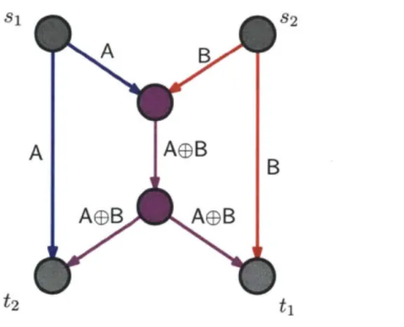
Figure 2-2, we have two source-sink pairs. Source node si look to transmit A to ti, while source node S2 aim to deliver B to t2. The same coding A E B on the central edge is then
referred to as inter-session coding, since A and B belong to different transmission sessions in this case. For a more detailed treatment of intra-session and inter-session coding, we refer the reader to [27]. In most of the thesis, we have a multiple unicast scenario, where each receiver requests a independent flow of packets. The choice of inter and intra session codings becomes important, especially regarding the decodability of the received packets, as covered in later chapters. In Chapter 3, we focus on intra-session coding, i.e. coding packet within the same flow, while in Chapter 4 we consider inter-session coding for rate gain. The capacity of non-multicast transmission over general network remains unsolved even for very simple cases. In this thesis, we shall not attempt to answer the problem regarding the rate region and achievability. Rather, we examine the existing generation based coding scheme on a particular network and investigate the possibility of improving coding performance under certain delay constraints characterized in our delay-rate trade-off framework.
t2 ti
Figure 2-2: A inter-session coding example of the butterfly graph: Source si transmits A to sink ti, while s2 transmit B to t2.
2.2
Coding Schemes and Delay Metrics
We start with the simplest transmission model. Consider a point-to-point communication system illustrated in Figure 2-3. The sender, denoted by Tx, is to communicate with the receiver, denoted by Rx, through a wireless erasure channel with packet erasure probability of e. In addition, a perfect feedback channel with delay D allows the receiver to send delayed feedback to the transmitter. The system is assumed to be time-slotted. At any time slot, the wireless packet erasure channel delivers at most one packet successfully, in the case when the packet is not erased. Otherwise, no packet is received at the receiver. A packet flow
f, arrives at the sender and is to be delivered to the receiver. The packets in this flow are
denoted as {Pf, Pf, ... , Pj, .. }. Each of them is treated as a length m vector in the space
F"
over some finite field Fq, i.e. Pf = [P1P/2 - ]T where P E Fq. For simplicity,we consider only the delivery of the first N packets of the flow and assume that all N data packets are assumed to be available at the sender prior to any transmissions. The results can be generalized to infinite packet flows. Furthermore, we assume that N is sufficient large such that N
>>
Kmax, where Kma,, is the maximum linear code block size, in terms of numberof packets. Next, we consider the typical fixed size generation-based network coding scheme and the adaptive scheme we propose.
Packets move into the coding bucket once previous packets in the bucket are decoded
Tx
Rx
D
Coding Bucket Eo Size of K packets: Determined by the Tx, adapting to the delay constraints at RxFigure 2-3: Adaptive linear network coding based transmission model: For the packet flow
f,
the transmitter (Tx) maintains a coding bucket G, whose size is adaptively determined based on the delay constraints at the receivers.2.2.1
Fixed generation-based Coding Scheme
In a fixed generation-based linear network coding scheme, the sender first chooses an integer
K > 1. It sequentially partitions the N packets into
F] generations {Gf,-
, Gf}. Eachgeneration G consists of K consecutive packets, i.e. G = {Pf +12'... ,in((i+1)KN)} The
generations of packets are transmitted sequentially according their generation indices. We
use G(= {P, f - , PK } to denote the Head of the Line (HOL) generation for transmission,
in which h = 1, - - is the generation index, and hk, k = 1,--- , K are the indices of
packets within the generation. In a time-slotted communication system, it is assumed that the sender has read all the packets in the HOL generation once the previous HOL generation is delivered. At every time slot t, the transmitter generates a coded packet P[t] that is a
linear combination of all packets in the HOL generation Gh (shown in Figure 2-5), i.e.
K
P[t ] =
(yak
[t ] Pf (2.1)k=1
where a t] = (aI[t], - , K[t]) is referred to as the coding coefficient vector for packet PIt].
Each coding coefficient vector is uniformly and independently chosen at random from FK [1].
The coded packet, with the coefficient vector appended in the header, is then sent to the receiver over the erasure channel.
The receiver collects coded packets over time, until it obtains K linearly independent packets to construct a full rank linear system of the K packets. For example, if the HOL generations contains P1,. .. , PK, and the K linearly independent packets collected
are Y1,..., YK, with coding coefficient vector ai = [aii ... aiK] for Y. We have the linear
system,
Y al a1 2 - - alK P11 P12 ... P1K a1 1 a1 2 ... alK P1
Y2 a21 a2 2 --- a2K P2 1 P22 ... P2K a21 a2 2 a2K P2
yK aKl aK2 ... aKK PK1 PK2 ... PKK aKl aK2 ... aKK PK
(2.2)
With all Y and a* known to the receiver, the full rank linear system can be solved by Gaussian elimination to recover all Pij and thus all packets P. Moreover, given a large enough field Fq, it is shown that with high probability [1], any K received packets are linearly independent. Therefore, in this thesis, we assume that a receiver is always able to decode whenever it receives K packets.
Once the receiver decodes the HOL generation successfully, it sends an ACK message through the feedback channel to the sender. The sender, who receives the ACK after a delay of D time slots, will purge the old HOL generation and move on to the next generation in the line. The process repeats until all the packets are delivered to the receiver.
2.2.2
Adaptive Linear Coding Scheme
Tx
Sending Coded Packets for the coding bucket
Shrink coding DI bucket size to 2 and empty bucket
Put new packets to the coding bucket and send coded packets
Collecting Coded
Packets Rx Decode Packets in the current bucket -- Send ACK Collecting Coded PacketsFigure 2-4: A session with varying coding bucket size. The initial coding bucket size is
3, containing packets {P1, P2, P3}. After finishing the three packets, the receiver decide to shrink the bucket size to 2, containing packets {P5, P6}.
Our scheme modifies such generation-based network coding in the following ways. The packets in the flow are not partitioned into generations prior to the transmissions. Instead, a
coding bucket is created and acts like the HOL generation. We use the term bucket to avoid
confusion with normal generation-based schemes. The size of the bucket in term of number of packets is denoted as K, like in the case of fix generation schemes. The sender collects information about user-end delay constraints and chooses the bucket size K dynamically. Therefore, the coding bucket size may change over time for the same packet transmission session. Figure 2-4 gives a simple example of the timing diagram of our adaptive scheme. At the beginning, the coding bucket has a size of 3 and contains three packets {P1, P2, P3}. The sender keeps transmitting encoded packets, i.e. P[1] to P[5], of these three packets. Some
Coding Bucket
iMe.. aK [t] a2a1
K = ak [t|Ph, k=1Figure 2-5: An illustration of encoding: the encoded packet P[t] is the linear combination of all packet in the coding bucket with coefficients ak [t] chosen randomly from some finite field.
of the coded packets, such as P[3] in this case, may be erased during the transmission. The receiver collects these coded packets until it has enough coded packets to decode all packets currently in the coding bucket, i.e. {P1, P2, P3}. This is done when it receives P[4] in this case. At this time, the receiver sends a ACK message back to the transmitter, and informs the latter to move on to new packets. Upon receiving the ACK feedback, the transmitter empties the bucket. We define all the transmissions between two bucket emptying actions to be a round of transmissions. A round of transmissions therefore includes all the transmissions taken place for all the packets in the current coding bucket to be delivered. In this example, the sender further decides to shrink bucket size to 2 for the next round of transmissions, possibly because of the tighter delay constraint experienced at the receiver. Therefore, only two packets {P4, P5} go into the bucket for the new round of transmissions. The process
repeats all packets are decoded at the receiver. We leave the details of adaptively determining coding bucket size to Chapter 3.
There are a few remarks regarding the adaptive coding scheme:
1. Packets stay in the coding bucket for the entire round of transmission. They are moved
into the coding bucket at the beginning of the round and purged from the bucket at the end of the round. This is to guarantee the random linearly coded packets are generated from the same group of original data packets and thus the correct decoding of the original data packets at the receiver. All the packets delivered in the same round of transmission are decoded together, as in the case of generation based schemes.
2. The size of the coding bucket remains the same throughput each round of transmission. In principle, the coding bucket size can be change within a round of transmission. For example, if the size increases, new packets can be introduced into the bucket. However, it is then more complicated to guarantee the correct decoding at the receiver. For simplicity, the change of bucket size within a round of transmission is not considered in the thesis.
3. The availability of feedback is important and is seen in may practical systems at
dif-ferent communication layer as discussed in Chapter 5. Feedback is only used when the receiver collects enough linearly independent coded packets. The transmitter is informed about the delay constraints at the receiver through some feedback channel or from the ACK message.
2.2.3
4,-Norm Delay Metrics
Now we define the delay metrics used in the paper. Following the notations used in the previous part, let T be the time slot in which the packet P is decoded at the receiver, and is delivered to upper layer. It is important that we require the delivery of original data
packets
{P, ...
,Pf }
to be in order. In the case when the sequence of packets decoded is
out-of-order, we assume that they are buffered at the receiver first, to ensure in-order final delivery. Let T represent the final in-order delivery times of packets PJ. Because of the in-order delivery, we have Ti T2 < ... TN. Consequently, it allows us to define theordered inter-arrival times AT of the original packets to as follows,
AzT
1 Ti+
D(2.3)
AT Ti - Ti_1, i = 2, -.-. , N, (2.4)
where D is the feedback delay from the receiver to the sender. Note that a feedback message
ACK is always assumed to be received correctly after D time slots. However, in the case
when there is more than one receiver, we assume that, in general, receivers experience differ-ent feedback delays across the system owing to its location and channel variations. Let the size of each data packet be L. We define the delay cost function as a metric of the following form,
1 (EN (E[ATi])P 1/p
d(p)
L
-
-
1N,
p
E
[1, oo),
(2.5)
where E[AT] is the expected value of AT. The expectation is taken over the distribution of packet erasures over the system and all the randomness associated with the coding and scheduling scheme, which are discussed in more detail in the next Chapter.
Mathematically, the delay metric is the fp-norm of the vector of expected inter-delivery times, i.e. [E[AT] . . .E[ATN] T, normalized by the total packet number and individual
packet size. Physically, however, p measures the sensitivity of the receiver toward the inter-packet delays. As discussed before, such delay sensitivity and is predominantly dependent on the type of applications running on the receiver. As the value of p varies from 1 to 00,
the delay function becomes increasingly biased towards the large components in the vector because of the f,-norm, hence indicating increasing user sensitivity toward large inter-packet delay. In particular, the two extreme values of p give two interesting interpretations of the delay metrics. First, consider the case when p = 1. Since
EN
E[AT] = E[TN] + D, thedelay in (2.5) simplifies to,
_E [TN] +±
d(1) = N (2.6)
LN
d(1), therefore, is equivalent to maximizing the average rate the receiver. On the other hand,
consider the case when p = o. Because of the infinity norm, the delay function in (2.5) reduces to,
d(oo) -maxi E[AT] (2.7)
L
Effectively, minimizing d(oo) translates into minimizing the maximum expected inter-arrival time between any two successive packets. We call this the per-packet delay.
The flexibility in choosing various p-value for delay metrics provides a unified way of looking at the delay sensitivity at the user side. If a user is downloading a file, he is certainly more concerned about shortening the overall completion time or average delay per packet. Consequently, d(1) is the appropriate delay cost function to be measured and optimized. On the other hand, if the user is running a real-time video applications that is extremely delay sensitive, then d(oo) is more likely to be the right cost function to be minimized as it allows sequence of packets to catch up quickly with respective delivery deadlines. Moreover, in between the two extremes, we can choose appropriate sensitivity value p for applications like progressive video downloading and even dynamically adjust the value according to the changing delay requirements.
2.2.4
Delay In Adaptive Coding Scheme
Next, we consider how these delay metrics can be applied in the coding scheme we discussed previously. We only need to examine the adaptive scheme, as the fixed generation scheme can be viewed as a special case when coding bucket size is a constant. In the adaptive coding scheme, a receiver will decode all packets in the current bucket before informing the sender to empty the bucket and move in new packets. Assume that the rate at which the coded packets are transmitted is r. Consider a round of transmissions of a bucket of K packets {Pi, -... P
}.
Once the receiver collects K linearly independent coded packets of the bucket, it decodes all K packets together. Hence, the ordered inter-arrival times of original packets will satisfy, E[ATi] =y
+ D and ATi, =-- ATiK = 0. In general, considerN is divisible by K, as the bucket size may only change when the bucket is emptied. The
packets will sequentially enter the bucket in groups of K packets. Then, for the inter-arrival time of the j-th packet, we have,
[ + D, if j=1 (mod K),
E[A Ti] = r (2.8)
0, otherwise.
Therefore, if the adaptive scheme chooses bucket size of K of a sequence of N packets, we can simplify (2.5) to measure the delay cost function for the transmission of the N packets, resulting in: 1_ j=(E[A Tjj])P1/ d(p) = K j (2.9) L (N 1L (L + D )P ) / = - (2.10) L N K + D r (2.11) LK1/P
In particular, under this coding scheme, the delay d(p) seen by the receiver over the period is independent of N as long as the coding bucket size remains to be K. Hence, we drop N and only consider the bucket size K for rest of the paper. Furthermore, in practice, K takes only positive integer values in [1, Kmax], where Kmax is the maximum bucket size, limited
by the maximum tolerable computation complexity of the target system. In this work, for
Kmax]-2.3
Geometric Programming
We give a concise primer of Geometric Programming (GP) techniques and terminology before looking specifically into the optimization problems associated with our system, as GP serves as the primary tool for the next chapter. For more comprehensive coverage of the topic, we refer the reader to [281, [29].
GP is a class of mathematical optimization problems characterized by some special forms
of objective functions and constraints. A typical GP is nonlinear and non-convex, but can be converted into a convex program so that a local optimum is also a global optimum. The theory of GP has been well studied since the 60s [30]. The convexity and duality of the these problems are very well understood. Well developed solution techniques, such as interior
point methods are capable of solving GPs efficiently even for large scale problems. Many
high-quality GP solvers are available (e.g. MOSEK package and CVX [31]) for providing robust numerical solutions for generalized GPs (GGP). GP or GGP see many applications in engineering design and analysis, as they can be used to model or approximate a wide variety of practical problems, especially in areas such as digital circuit design. In wireless communication, GP is often used to solve transmission power control problems [29].
Consider a vector of decision variables x = [x1 ... xn]T. A real function g : Rn -+ R is
said to be a monomial if it can be written in the form,
n
g(x) = cJxy , (2.12)
i=1
where the coefficient c is positive, and the exponents a,. . . , an are arbitrary real numbers.
A function
f
: R -+ R in the formK n
f(x) =
ck1
Fxik,
(2.13)
k=1 i=1
with all ck being positive real numbers, is called a posynomial. A posynomial is the sum of arbitrary number of monomials. On top of this, any function
f,
which can be constructedwith posynomials using addition, multiplication, positive power and maximum operations is called a generalized posynomial.
A standard form geometric program is presented as follows,
minimize fo(x)
subject to fi(x) 1, i 1, ... , m, (2.14)
gj(x) = 1, j = 1 - -- P,
where fi(x) are posynomials and gi(x) are monomials, and x are the decision variables, which are also implicitly assumed to be positive, i.e. xi > 0, i = 1,..., n. In particular, the objective of the optimization has to be minimizing some posynomial. That says, for solving maximization problems with GP, the objective function has to be in the form of some monomial g(x), so that instead of maximizing g(x), we can minimize 1, which is itself a monomial. In the case where any fi(x) is a generalized posynomial, the optimization program is said to be a generalized geometric program (GGP). All generalized geometric programs can be converted into standard geometric programs and solved efficiently.
Note that GP in its standard form is convex, because posynomials in general are non-convex functions. In order to apply general non-convex optimization methods, a GP is usually transformed into its convex form through logarithmic change of variables and multiplica-tive constants as follows. Let y, = log x so that xi =ey, the standard form GP can be transformed into its equivalent convex form,
minimize log fo (es)
subject to log
fi(ey)
< 1, i 1,... ,m, (2.15) loggj(ey) = 1,j
1,... ,p.In particular, a monomial constraints
n
gj (x) = dj 1 x'ik -1 (2.16)
is converted to n
log gj (ey) = log d + EZaik yk = 0, (2.17) k=1
which is affine and convex, while a posynomial constraint
Ki (1) (2) (n)
f(X) = cikX ik Xaik ... Xnik < 1 (2.18)
k=1
is converted to
Ki
p(y) = log exp(a'y + log cik) 0, (2.19)
k=1
where aik= [a~ia (~2) . (n) -u-x ucin
ik ik ... ak] is the vector of exponents. Since pi(y) is a log-sum-exp function, which is shown to be convex, all the constraints turn out to be convex after the transfor-mation. Therefore, although the original standard formulations of GPs are nonlinear and non-convex, they can be converted into convex form as in (2.15) and solved efficiently with standard convex program solution techniques.
Chapter 3
Joint Coding and Scheduling
Optimization with Varying Metrics
Now we are ready to investigate the coding and scheduling optimization in our motivating scenario of typical home network settings. The home network we consider is generally con-figured as follows. Multiple user networking devices, such as computers, media players and gaming consoles, are wirelessly connected to one or more WiFi access points (AP). These access points are then linked with a home gateway to the Internet. All the flow of packets from the Internet to the user devices goes through the gateway and the access points. The applications running on different devices may have very different delay sensitivities and con-straints, as discussed before. The gateway and the access points look for the optimal coding and scheduling parameters to ensure the QoE of all the users devices within the network.
3.1
Single Broadcast Channel With Packet Erasures
First, we consider the case where is only a single WiFi access point and a single broadcast channel connecting all user devices. This is the typical scenario with most of the existing small home networks.
3.1.1
System Model
Conceptually, we represent the system using the following model. We assume that the link between the AP and gateway has a high capacity and is lossless. It is reasonable as the bottleneck of such system is usually the wireless connection between AP and the user devices. Furthermore, in many cases, the gateway and the access point is one integrated device itself. Consequently, we represent both the gateway and the AP together as a single
node s. We denote the set of receivers by T = {ti, -- - , tM}. Each receiver needs to obtain a
flow of packets from some source over the Internet. Let F = {fi, - - -, fM} be the set of flows,
where
fj
is the packet flow requested by receiver ti. Note that allfi
enter the system from node s, which in turn acts as a source node in our model. The flows for different receivers are assumed to be independent. Hence, we have a single source multiple unicast session in the network. The original data packets in each flow are numbered, with Pf representing the j-th packet in flowfi.
We assume that there are always enough packets to be served for each flow, since that is the case when there is a heavy traffic condition. Furthermore, all packets are assumed to have the same size L in the system and the system is time slotted. As in the previous chapter, at every time slot, the node s is able to broadcast a sizeL packet to all receivers, through the packet erasure broadcast channel. Erasures happen
independently across all receivers and all time slots, i.e. the channel is memoryless. We denote the erasure vector by e = [E - -E], where Es represents the erasure probability seen
M
by receiver tj. Figure 3-1 gives an illustration of the system model in the discussion. Note
that the transmission is wireless broadcast, which means that receivers are able to overheard packets destined to other receivers.
Scheduling Strategies
Most of the works we discussed in Chapter 1 focus on linear network codes for multicast, in which all the receivers request the same content from the sources and any coding is done within the same session. In the system we consider here, however, we have a multiple unicast scenario, as each sink looks to receive its own flow, independently from others. Unlike the
Coding Buc (Note flows have differe bucket sizes fMw-'3 no-w fM kets can Gateway & AP s E EM f-1
~MtM
Figure 3-1: System model with single transmitter s and M receivers {ti,... , tM}. Flow
fi
is requested by ti, while Gf, represents the coding bucket for flow
fi.
simple scenario described in the previous chapter, the resource at node s has to be shared among all the receivers. In this chapter, only intra-session coding is considered. As a result, for every time slot, the sender s has to make a decision on which receiver to transmit to. It will then broadcast the encoded packet for that particular receiver. Moreover, if no inter-session coding is present, a receiver will discard any overheard packets which are targeted to some other receiver, since these packets are not useful for him. In this case, some scheduling algorithm is necessary to determine which receiver to serve for each time slot. While many sophisticated scheduling algorithms are available, for simplicity, we use a simple stochastic scheduling algorithm as follows. At every time slot, the source node s serves receiver tj or flow
fj
with probability a3, independently from of any other time slots. In the long run,equivalently, the transmitter node s is spending a, portion of time serving receiver tj. We call the vector a = (ai, - , am) the vector of scheduling coefficients.


![Figure 2-5: An illustration of encoding: the encoded packet P[t] is the linear combination of all packet in the coding bucket with coefficients ak [t] chosen randomly from some finite field.](https://thumb-eu.123doks.com/thumbv2/123doknet/14353239.501307/30.918.210.586.127.452/figure-illustration-encoding-encoded-packet-combination-coefficients-randomly.webp)

![Figure 3-3: Min rate vs delay sensitivity pi of different coding methods for an example system with 5 receivers, D = 5, L = 1 and erasures e = [0.4, 0.1, 0.15, 0.2, 0.25]](https://thumb-eu.123doks.com/thumbv2/123doknet/14353239.501307/50.918.211.740.122.502/figure-sensitivity-different-coding-methods-example-receivers-erasures.webp)
