HAL Id: hal-01563340
https://hal.archives-ouvertes.fr/hal-01563340
Submitted on 24 May 2019
HAL is a multi-disciplinary open access
archive for the deposit and dissemination of
sci-entific research documents, whether they are
pub-lished or not. The documents may come from
teaching and research institutions in France or
abroad, or from public or private research centers.
L’archive ouverte pluridisciplinaire HAL, est
destinée au dépôt et à la diffusion de documents
scientifiques de niveau recherche, publiés ou non,
émanant des établissements d’enseignement et de
recherche français ou étrangers, des laboratoires
publics ou privés.
Wave and Current Generation in Wave Flumes Using
Axial-Flow Pumps
Aurélien Babarit, Simon Delvoye, Vincent Arnal, Laurent Davoust, Jeroen
Wackers, Félicien Bonnefoy
To cite this version:
Aurélien Babarit, Simon Delvoye, Vincent Arnal, Laurent Davoust, Jeroen Wackers, et al.. Wave
and Current Generation in Wave Flumes Using Axial-Flow Pumps.
36th International
Confer-ence on Ocean, Offshore and Artic Engineering (OMAE2017), Jun 2017, Trondheim, Norway.
�10.1115/OMAE2017-61404�. �hal-01563340�
WAVE AND CURRENT GENERATION IN WAVE FLUMES USING AXIAL-FLOW
PUMPS
Aur ´elien Babarit, Simon Delvoye, Vincent Arnal, Laurent Davoust, Jeroen Wackers, F ´elicien Bonnefoy
Ecole Centrale de Nantes - CNRS Nantes, France
ABSTRACT
We investigate a new concept for wave and current genera-tion. It consists of axial-flow pumps driven such as to generate an oscillatory flow through an orifice located at one end of the flume. Oscillations of the flow lead to the generation of water waves at the free surface. If the average of the flow is different from zero, a current is generated that superposes on the waves. In this study, we explored the technical capabilities of this con-cept and the influence of geometric parameters on wave and cur-rent generation. We used numerical and experimental modelling. Most noticeably, the numerical results indicate that this concept is well suited for the generation of long and high waves. An experimental setup has been designed and built. We used it to make an experimental proof of concept for the wave and current generation, including waves propagating against the current.
INTRODUCTION
The usual approch to generate waves in wave tanks is to use rigid bodies with oscillating motions. Current is usually gener-ated using pumps and a circulating duct under the bottom of the tank or a circulating channel on the side of the tank. Wave and current generation is usually obtained by combining the two sys-tems. This architecture can be found in wave tanks at SINTEF Ocean in Norway, at MARIN in The Netherlands, in France at Ifremer Boulogne or Oc´eanide.
From the physics’ point of view, wave generation is the re-sult of the application of an oscillating normal velocity boundary condition on the wall of the tank [1]. Wave propagation being a deterministic process, any system that can generate the same
boundary condition as a conventional wavemaker (say a bottom hinged flap or piston-type wavemaker) shall achieve the same wave generation in the tank.
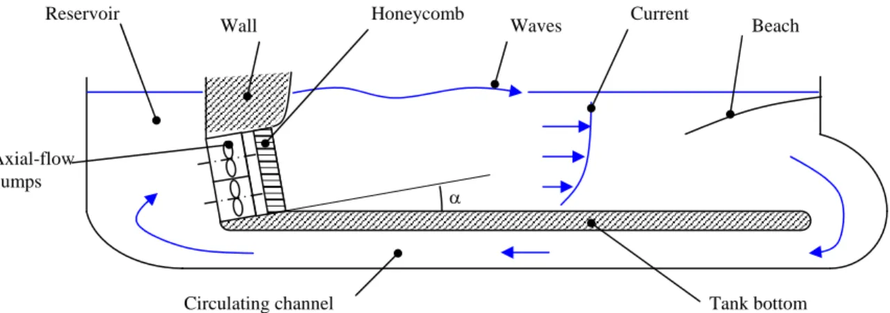
Elaborating on this idea, Ecole Centrale de Nantes has pro-posed a new wavemaking system using axial-flow pumps instead of rigid bodies [2], see Fig. 1. The axial-flow pumps are located in ducts that connect the wave flume to a back reservoir. The pumps are controlled in order to generate an oscillating flow. At the outlet of the duct on the wave flume’s side, the flow velocities are similar to the ones obtained with conventional wavemakers. Therefore, waves are generated in the wave flume.
A first unique feature of this system is that it can generate both waves and current. Indeed, current can easily be obtained by adjusting the control of the axial-flow pumps such as the average flow through the ducts is non-zero. In this case, obviously, it is mandatory for current generation to include a circulating duct or a circulating channel connecting the end of the wave flume back to the back reservoir. Depending on the orientation of the average flow , one can generate conditions with waves propagating with or propagating against the current.
A second interesting feature of the proposed system is that it makes it easier to generate large amplitudes waves than with conventional wavemakers. Indeed, the wave amplitude is limited by the maximum available stroke for conventional wavemakers. As an example, Fig. 2 shows a comparison of measurements of the maximum wave height in the large wave tank of Ecole Centrale de Nantes and the maximum wave height that can be obtained when the wavemakers are used with maximum stroke (1.76 m). The finite stroke limit was obtained using the linear wavemaker theory [1]. For wave periods above 4 s, one can see
Honeycomb Axial-flow pumps Beach Tank bottom Circulating channel Waves Current Wall Reservoir α
FIGURE 1. SKETCH OF THE PROPOSED WAVE AND CURRENT GENERATION SYSTEM.
Period (s) H ei gh t (m ) 1 2 3 4 5 0 0.5 1 1.5 2 2.5
ECN’s wavemaker capabilities Finite stroke limit
FIGURE 2. COMPARISON OF MEASUREMENTS OF THE MAX-IMUM WAVE HEIGHT IN THE LARGE WAVE TANK OF ECOLE CENTRALE DE NANTES AND CALCULATIONS USING THE LIN-EAR WAVEMAKER THEORY OF THE WAVE HEIGHT FOR A STROKE OF 1.76 m. FOR WAVE PERIODS BELOW 2.5 s, THE WAVE HEIGHT IS LIMITED BY WAVE BREAKING. BETWEEN 2.5 AND 4.5 s, IT IS LIMITED BY THE MAXIMUM POWER OF THE ELECTRIC MOTORS. ABOVE 4 s, THE WAVE HEIGHT IS LIM-ITED BY THE MAXIMUM STROKE OF THE WAVEMAKERS.
that the height of the generated waves is limited by the finite stroke. This limitation does not apply to the proposed system.
Therefore, it appears that the proposed system may be a rel-evant alternative to conventional technologies for wave and cur-rent generation in the context of ocean engineering. Exploratory studies have been conducted at Ecole Centrale de nantes in or-der to further investigate its potential. It includes a parametric study using numerical modelling in order to assess the effect of
geometric and dynamic parameters on the generated wave char-acteristics. Using the results of the parametric study, an experi-mental set-up was designed and built . It allowed an experiexperi-mental proof-of-concept that included generation of waves propagating against the current. The aim of the present paper is to present those works.
PARAMETRIC STUDY
List of identified relevant parameters
For the new system, there are many geometric parameters that can have a significant effect on the characteristics of the gen-erated wave and current:
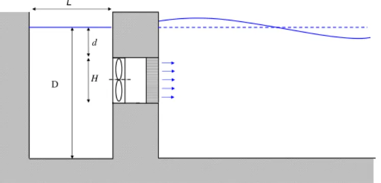
- Submergence depth of the duct outlet (distance d in Fig. 3). In deep water conditions, it is expected that the duct outlet should be close to the free surface for high energy efficiency. However, the minimum distance to the free surface may be limited by the amplitude of the maximum wave troughs to avoid ventilation at the axial-flow pumps, which could be damaging. Therefore, the submergence depth of the duct outlet is expected to be a trade-off between energy efficiency and the maximum design wave amplitude.
- Ratio of the duct outlet’s height to the water depth and an-gle of the duct axis with respect to the bottom of the flume. For current generation, the most homogeneous horizontal velocity profile across the water column is expected to be obtained with the height of the duct outlet (distance H in Fig. 3) equal to the depth of the flume (denoted D in Fig. 3). However, this configuration is not possible in practice be-cause it could lead to ventilation issues for the pumps in the wave troughs. Therefore, the top of the outlet duct should be sufficiently submerged. To avoid a deficit in the current velocity profile close to the free surface, the duct axis should
D d
H L
FIGURE 3. DEFINITIONS OF TOP OUTLET DUCT SUBUMER-GENCE DEPTH d, OUTLET DUCT HEIGHT H AND DUCT LENGTH L.
- Geometries of the duct inlet and outlet, duct and honey-comb length (see Fig. 1). A honeyhoney-comb is required at the duct outlet in order to filter out large eddies that could be generated by the pumps and reduce the turbulence level in the flume. The geometries of the duct inlet and outlet, of the duct and of the honeycomb govern the head losses through the system. They may have a significant effect on the en-ergy efficiency of the system. Also, the geometry of the duct outlet may have an influence on the generation of parasitic waves (free or bound harmonic waves).
- Length of the back reservoir (denoted L in Fig. 3)). De-pending on its length, sloshing may occur in the back reser-voir. It could make the duct inlet flow conditions (pressure, velocities) vary with time which could be an issue for the pumps (particularly with respect to control). Sloshing issues may be reduced by adding a wave damping system in the back reservoir. It may be a damping beach, wave-screens or even floats or floating mats on the free surface.
- Geometry of the inlet of the circulating duct at the end of the wave flume (see Fig. 1). It is expected that it is critical for the quality of the current in case of generation of con-ditions with waves propagating against the current. Also, it creates a head loss thus it has an effect on the energy effi-ciency of the system.
Obviously, the waves and current in the wave flume also de-pend on the dynamic characteristics of the volume flow rate at the duct outlet. They are:
- Average volume flow rate. The average volume flow rate through the pumps sets the current including the direction of the current.
- Spatial homogeneity of the horizontal velocity. The best configuration is when the velocity profile at the duct outlet corresponds to the target flow (which can be waves only,
waves and current, current only). If there are large variations of the flow velocity in the vertical directions (waves in deep water condition, sheared current), it may be relevant to use columns of independently controlled pumps (several pumps located on top of each other).
- Harmonic content (amplitudes and phases of the harmon-ics). The harmonic content of the volume flow rate at the duct outlet should be controlled according to the wave con-ditions (regular or irregular waves, deep water or finite water depth conditions). Like for wave generation with conven-tional wavemakers, it may be necessary to include correc-tive terms in the control of the axial-flow pumps to reduce the rate of parasitic waves [3].
Effect of submergence depth and heigth of duct outlet Here, the technical characteristics of the large wave tank of Ecole Centrale de Nantes are used as references. Its water depth is 5 m. The wavemakers are oscillating flaps. Their height is 2.85 m. Thus, we chose to study the effect of the submergence depth of the top of the outlet duct (heigth d d in Fig. 3) while maintaining the total height of the submergence depth and duct outlet equal to the height of the flaps of Ecole Centrale de Nantes’ wave tank (i.e d + H = 2.85 m).
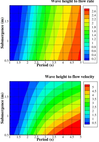
The well-known wavemaker theory is used [1]. We assume that the wave making system generates a perfect uniform hori-zontal velocity through the duct outlet. The MATLAB routines developed by Meylan [4] were used to calculate the amplitude of the propagating mode and the amplitudes of the evanescent modes. We varied the duct outlet top submergence depth and the wave period. Results for the ratio of the propagating mode’s wave height (two times the amplitude) to the amplitude of the volume flow rate through the duct outlet are shown in Fig. 4 as well as results for the ratio of the wave heigth to the horizontal flow velocity amplitude.
As expected, one can see that, for a given wave period, the wave heigth decreases with increasing submergence depth. As-suming that a key technical constraint of the axial-flow pumps is the maximum volume flow rate that they can deliver, it shows that the top of the duct outlet should be as close as possible to the free surface for high wave generation.
Less intuitively, one can see that the ratio of wave height to volume flow rate or horizontal velocity increases with increasing wave period. In other words, the longer the wave period is, the greater the wave heigth will be. This is a clear advantage of the proposed new wave making system versus conventional wave-makers, for which the maximum wave height decreases with in-creasing wave period because of stroke limitation (see Fig. 2). It shows that the proposed new system is well suited for large and long waves generation. For example, with a duct outlet of 1.85 m and a top submergence depth of 1 m, a system that could
Period (s) S u b m er ge n ce (m ) 1 1.5 2 2.5 3 3.5 4 4.5 5 0.5 1 1.5 5 4.5 4 3.5 3 2.5 2 1.5 1 0.5
Wave height to flow velocity Period (s) S u b m er ge n ce (m ) 1 1.5 2 2.5 3 3.5 4 4.5 5 0.5 1 1.5 2.6 2.4 2.2 2 1.8 1.6 1.4 1.2 1 0.8 0.6 0.4 0.2
Wave height to flow rate
FIGURE 4. RATIO OF PROPAGATING MODE’S WAVE HEIGHT TO VOLUME FLOW RATE AMPLITUDE (TOP, IN m/(m2.s−1)) AND TO FLOW VELOCITY AMPLITUDE (BOTTOM, IN m/(m.s−1)) AS FUNCTIONS OF WAVE PERIOD AND TOP SUBMERGENCE OF DUCT OUTLET .
a wave of 2 m height for a period of 4 s. For this configuration,
a flow rate of 1 m3.s−1 corresponds to a maximum horizontal
flow velocity through the duct outlet of 0.54 m.s−1. This level of
flow velocity appears rather moderate, thus we believe that it is achievable in practice. For sake of comparison, it would require a stroke of approximately 4 m for the flap-type wavemaker of ECN’s large wave tank to generate waves of the same height and period.
Optimization of duct geometry
The wavemaker theory is not relevant to study the effect of the details of the duct geometry on wave and current generation, mainly because of the assumption of irrotational flow. There-fore, we developed a bidimensional numerical model using the
Navier-Stokes solver ISIS-CFD [5] (which is a component of the numerical framework FINE/Marine). Now, the length of the wave flume is 30 m and the water depth is 1 m. The recirculation duct is located beneath the flume bottom. This numerical model allows the effect of details of the duct geometry to be studied
in-cluding the effect of the angleα(see Fig. 1) and the effect of the
shape of the duct outlet.
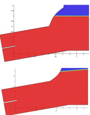
Figure 5 shows an example of wave generation simulated with the numerical model. We consider that the pumping systems consist of two 40 cm diameter axial-flow pumps one on top of the other. The effect of the axial-flow pumps is taken into account by prescribing the flow velocity at the location of the pumps (black line across the flow in the middle of the duct in Fig. 5). The pumps are separated by a wall parallel to their axis. The total height of the duct is H = 80 cm (see Fig. 3). Let us recall that the water depth is D = 1 m, thus the water clearance above the top of the duct’s outlet is 20 cm.
The exact geometry of the axial-flow pumps and of the hon-eycomb hasn’t been modelled. Note that they could have been with ISIS-CFD. However the numerical complexity (mesh com-plexity and CPU time) would have been disproportionate to the objectives of this concept study. Instead, we used a simplified ap-proach. A homogeneous flow velocity field has been prescribed at the location of the pumps (black lines across the flow in the middle of the duct in Fig. 5). This approach assumes that the physical effect of the honeycomb is perfect in terms of filter-ing the eddy structures and smoothfilter-ing the spatial variation of the flow velocity. It does not take into account the injection of resid-ual turbulence in the flow.
The SST k-ωturbulence model was used. Starting from zero
velocity, a ramp was found to be unnecessary for the introduction of the pump velocity in case of wave generation only. However, a ramp was found to be critical in cases of current generation to avoid exciting the sloshing modes of the flume. A ramp duration of 40 s was used. Mesh convergence was obtained for meshes
with number of cells of order of 105. The computational time
was of order of 1 h per wave period on a 5 years-old desktop computer.
Figure 5 shows a snapshot of the wavefield in the wave flume and in the back reservoir after approximately 10 s of simulation time. The wave period is 2 s in this simulation. On the right, one can see that waves have been generated and propagated from the wavemaker. Close to the wavemaker, one can see that the system also generates higher harmonic waves despite the regular forcing (the prescribed flow velocity at the pumps varies sinu-soidally with time with a 2 s period). Like for wave generation with conventional wavemakers, it may be necessary to include corrective terms in the control of the axial-flow pumps to reduce the rate of these parasitic waves. Building on the work of [3], we implemented corrections in the prescribed flow velocity, but it didn’t improve the results so far. Further research appears to be necessary.
FIGURE 5. EXAMPLE OF WAVE GENERATION SIMULATED USING THE ISIS-CFD BASED NUMERICAL WAVE FLUME. THE EFFECT OF THE AXIAL-FLOW PUMPS IS MODELLED BY PRESCRIBING THE FLOW VELOCITY AT THE LOCATION OF THE PUMPS (BLACKS LINE ACROSS THE FLOW IN THE MIDDLE OF THE DUCT). THE WAVE PERIOD IS 2 s.
On the left in Fig. 5, one can see that waves are also gener-ated in the back reservoir. They may have an effect on the overall dynamic response of the system. To mitigate this effect, it may be necessary to include wave damping systems in the back reser-voir. This has not been investigated yet.
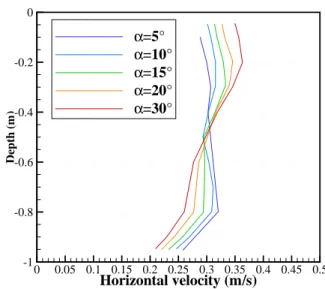
Optimization of angleα. The angleα is a key param-eter regarding the homogeneity of the horizontal flow velocity in case of current generation. Angles of 5o, 10o, 15o, 20o and 30o were tested numerically. The horizontal velocity profile at a distance of 12 m from the wavemaker for each configuration is shown in Fig. 6.
As expected, there is a significant deficit in the horizontal velocity close to the flume bottom which can be explained by the development of the bottom boundary layer. One can see that its thickness is approximately 20 cm at 12 m of the wavemaker. It appears that there is also a deficit in the horizontal velocity close to the free surface. It may also be explained by friction of the upper water layer with the air on top of the flume.
Overall, one can see that the velocity profile is the flatest for inclination angles of 5o and 10o. For 10o. However, one may notice a small deficit in the velocity in the middle of the water column for the 10o configuration, which is the signature of the separating wall between the two axial-flow pumps in the numerical model (see Fig. 5).
Optimization of duct’s outlet shape. It may be ex-pected that the shape of the duct’s outlet has an effect on the quality of the generated waves. To measure the quality of the waves, we have chosen the rate of generated harmonics (ratio of the amplitude of parasitic waves with respect to the ampli-tude of the targed wave). Several shapes have been tested among which two examples are shown in Fig. 7. The amplitude of the parisitic waves have been measured using an array of numerical wave gauges Surprisingly, results indicate that, for all the
con-Horizontal velocity (m/s) D ep th ( m ) 0 0.05 0.1 0.15 0.2 0.25 0.3 0.35 0.4 0.45 0.5 -1 -0.8 -0.6 -0.4 -0.2 0 α=5° α=10° α=15° α=20° α=30°
FIGURE 6. COMPARISON OF VERTICAL PROFILE OF THE HORIZONTAL FLOW VELOCITY FOR SEVERAL ANGLESα OF INCLINATION OF THE WAVE AND CURRENT GNERATION SYS-TEM.
figurations that have been tested, the effect of the shape of the duct’s outlet on the quality of the generated waves is negligible.
EXPERIMENTAL VALIDATION
To further qualify the new wave and current generation sys-tem, a new wave flume has been designed and built at Ecole Cen-trale de Nantes. It is immersed in the circulation channel of Ecole Centrale de Nantes. The numerical findings were used for the de-sign of the experimental set-up. A 1/3 scale was chosen with re-spect to the dimensions of the numerical wave flume. The length
FIGURE 7. EXAMPLES OF SHAPES THAT HAVE BEEN TESTED FOR THE DUCT’S OUTLET.
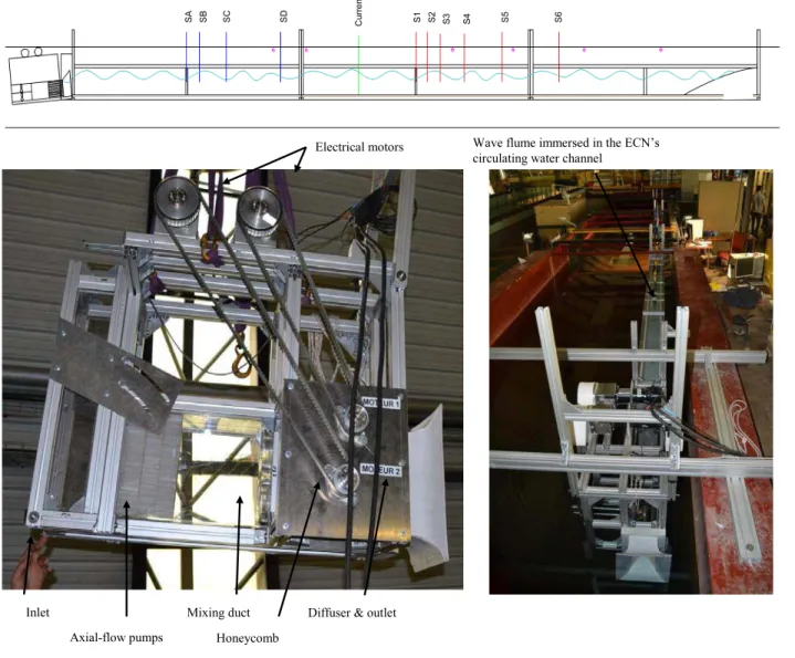
of the flume is 12 m, the water depth is 0.36 m. The width of the flume is 0.144 m. A damping beach is included at one end of the flume. Figure 8 shows a sketch and pictures of the experimental set-up.
The wave flume was built with ARCANE modular alu-minum rails. The walls are made with Komacell PVC sheets (10 mm thickness). The wave and current generation system con-sists in a structure on which are mounted the equipments. The
structure allows the inclination angleα between the axis of the
duct and the bottom of the flume to be varied. The wave and cur-rent generation system includes two 1.5 kW DC electric motors (Parvex 5S540C) mounted on the top of the supporting structure. They drive using a belt the shafts of two propellers that are used as axial-flow pumps. The propellers are Side Power SE30 bow thrusters. The diameter of the propellers is 125 mm. Each is mounted in a cylindrical duct of 126 mm internal diameter. The cylindrical ducts are connected to a greater duct with rectangular section. Its length and its height are 500 mm. It is expected to allow the flows from the two propellers to be mixed. Then, the flow goes through a honeycomb whose length is 250 mm. Fi-nally, a diffuser allows a smooth transition from ducted flow to free surface flow.
The wave elevation is measured using resistive wave gauges at several locations in the wave flume. The current is measured using a cup-type current meter. The current meter is mounted on a mast that allows the current to be measured at several depths in the water column. Velocitymeters were mounted on the shaft of the electrical motors in order to to control the rotational velocity. Both motors are controlled with the same control law. Feed-in current and voltage to the motors were measured to calculate the overall energy efficiency of the system.
Current generation capability
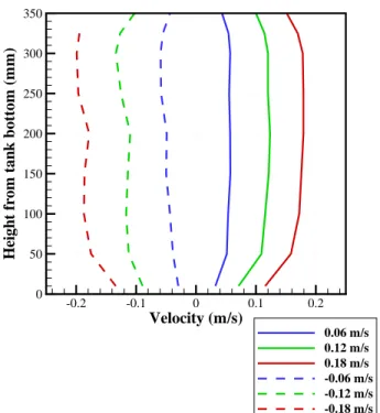
Firstly, we investigated the effect of the inclination angleα
on the velocity profile at a distance of 5 meters from the wave-maker. The vertical profile of the velocity was measured for 5o, 10o, 15o and 20o. The experimental results confirmed the nu-merical results: the most homogeneous profiles were obtained with the smallest angles. In the following, 5o has been retained for the inclination angle. Figure 9 shows the vertical velocity profile for several rated velocities. Tests included the generation of negative current (current coming from the end of the flume to the wavemakers) which was obtained by changing the direction of rotations of the propellers. One can see that the homogene-ity of the current is very good for positive currents. For negative currents, it is not as good as for positive currents but we believe that it is still acceptable. The difference in the quality of the ver-tical velocity profiles between positive and negative currents is attributed to the different end conditions between the two cases.
Wave generation capability
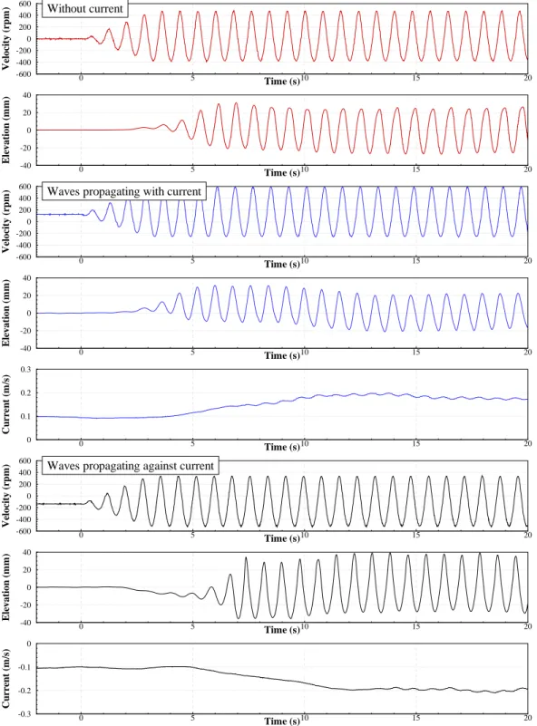
For wave generation, the rotational velocity of the electric motors is controlled. It follows a harmonic function. The same control is applied to both motors. The period and the ampli-tude of the rotational velocity are varied in order to quantify the wave generation capabilities of the set-up. The top two graphs in Fig. 10 show the results of an experiment with period 0.8 s and motors’ rotational velocity amplitude 400 rpm. The motors are started at t = 0 s. As expected, one can see that waves are generated and that they propagate in the wave flume. In this ex-ample, the wave height is approximately 45 mm. Fourier analysis was performed on the wave signal. It showed that the generated waves are not perfect. Parasitic harmonics are also generated by the system.
In the experiments, it was observed that the measured wave height decreases with increasing distance from the wavemaker, see Fig. 11. This phenomenon can be explained by wall friction on the wall of the flume [6]. The decay rate is related to the flume width (the narrower the flume is, the greater the decay rate will be). Using linear curve fitting, the wave height for a wide flume was estimated from the experimental results.
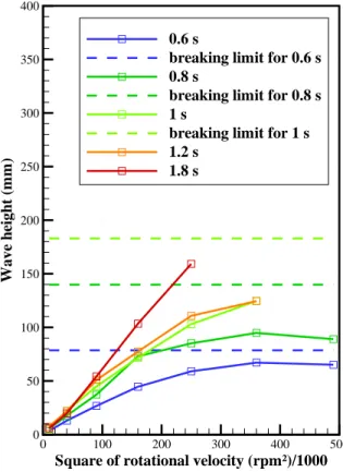
Figure 12 shows the wave height (extrapolated for a wide flume) as a function of the square of the rotational velocity
am-FIGURE 8. SKETCH (ON TOP) AND PICTURES (ON THE LEFT: WAVE AND CURRENT GENERATION SYSTEM, ON THE RIGHT: AS-SEMBLED WAVE FLUME IN THE CIRCULATING WATER CHANNEL) OF THE EXPERIMENTAL SETUP THAT WAS INSTALLED AND TESTED IN THE CIRCULATING WATER CHANNEL OF ECOLE CENTRALE DE NANTES. THE SKETCH SHOWS THE LOCATION OF THE WAVE PROBES (RED AND BLUE LINES) AND THE CURRENTMETER (GREEN LINE).
plitude and for several wave periods. One can see that, up to
ap-proximately 500 rpm (250 000 rpm2), the wave height increases
linearly with the square of the rotational velocity amplitude. It can be explained by recalling that, for a propeller, the thrust force is related to the square of the rotational velocity. From the fluid perspective, the thrust corresponds to a pressure over a surface perpendicular to the flow. In wave theory, the pressure is di-rectly proportional to the wave height, thus it makes sense that the wave height is linearly related to the square of the rotational
velocity amplitude. Above 500 rpm (250 000 rpm2), one can see
the wave height - rotational velocity curves curve until reaching a limit which depends on the wave period. This limit is signif-icantly smaller than the breaking limit. At present, the reasons for this difference are unclear to us.
Figure 12 also shows that the wave height increases with increasing period for a given rotational velocity amplitude. For a rotational velocity of 500 rpm, the increase appears to be ap-proximatively linear with the period (59 mm wave height for a
Velocity (m/s) H ei gh t f rom t an k b ot tom ( m m ) -0.2 -0.1 0 0.1 0.2 0 50 100 150 200 250 300 350 0.06 m/s 0.12 m/s 0.18 m/s -0.06 m/s -0.12 m/s -0.18 m/s
FIGURE 9. VERTICAL VELOCITY PROFILES MEASURED AT 5 m FROM THE WAVEMAKERS. THE REFERENCE VELOCITY CORRESPONDS TO THE MEASUREMENT AT A HEIGHT OF 200 mm FROM THE FLUME BOTTOM.
0.6 s period, 110 mm for a 1.2 s period and 160 mm for a 1.8 s period). This is interesting from a technical perspective because it confirms that the system is well suited for the generation of large amplitude waves. For sake of comparison, it would require a stroke of 0.2 m for a piston wavemaker to generate a wave of 160 mm with 1.8 s period. Note that we were not able to gen-erate greater waves than shown in Fig. 12 in the experiments (which would require an even greater stroke for a piston-type wavemaker) because we were limited by the height of the flume walls. They were not tall enough to avoid water spilling.
At this point, we must point out that, in our experiments, it was observed for finite depth and shallow water conditions that the wave quality is not sufficient for the new system to compete with conventional wavemakers. Indeed, the rate of generated har-monics is high in these conditions. However, it is well known that for finite depth conditions, the control of piston-type wavemakers requires corrections to be taken into account in order to achieve good quality of wave generation [7], [3]. Thus, the deficiencies of our system may be adressed also by including corrections in the control of the motors.
Wave and current generation capability
Wave and current can be generated by superimposing the control laws for wave generation and for current generation for the control of the rotational velocity of the motors. The result is a shifted harmonic function with average velocity governing the current intensity. Depending on the sign of the average velocity, waves propagating with or propagating against the current can be generated.
The graphs in the middle in Fig. 10 shows experimental re-sults for a control with a 0.8 s period, an amplitude of variation of the rotational velocity of 400 rpm and a positive rotational velocity average of 150 rpm. Like in previous cases, the same control is applied to both motors. In the experiments, the motors were set in rotation at average speed first an we waited until the current was established (t < 0 in third graph of Fig. 10). Then, variations of the rotational velocity were applied. A ramp of du-ration 3 periods was applied when starting wave genedu-ration in order to allow a smooth transition between conditions with cur-rent only and conditions with curcur-rent and waves. One can see that waves were generated in addition to the current. The wave height, in order of 40 mm, appears to be smaller than in the case without current. Comparing the wave elevation signal with and without current, one can see that the first waves reach the wave gauge faster with the current. It is expected since the waves were following the current in this experiment. Also, one can see that, at the location were we measured current, the current goes faster with the waves (approximately 0.2 m/s) than without (approx. 0.1 m/s). The change in average velocity may be explained by wave and current interactions [8].
Last three graphs in Fig. 10 shows results for an experiment with period 0.8s, an amplitude of variation of the rotational ve-locity of 400 rpm and a negative rotational veve-locity average of 150 rpm. The current is negative: it goes from the end of the flume towards the wavemaker. Without the waves, the current velocity is approximately 0.1 m/s. Like in the previous, super-posing variations of the rotational velocity on the rotational ve-locity average allows waves to be generated. In comparison to the cases with waves propagating with current or without cur-rent, the wave height is significantly greater (approximately 70 mm). Also, one can see that the waves reach the wave gauge significantly later because of the current that slows down energy propagation. The current velocity also increases with the waves going from approx. -0.1 m/s to -0.2 m/s. Again, the change in average velocity may be explained by wave and current interac-tions [8].
CONCLUSION
In this study, we showed a numerical and experimental proof of concept for a new wave and current generation system in wave flumes. The system consists of axial-flow pumps controlled to generate an oscillatory flow through an orifice located in one of
Time (s) V el oc it y (r p m ) 0 5 10 15 20 -600 -400 -200 0 200 400 600 Without current Time (s) El evat ion ( m m ) 0 5 10 15 20 -40 -20 0 20 40 Time (s) V el oc it y ( rp m ) 0 5 10 15 20 -600 -400 -200 0 200 400 600
Waves propagating with current
Time (s) El evat ion ( m m ) 0 5 10 15 20 -40 -20 0 20 40 Time (s) C u rr en t ( m /s ) 0 5 10 15 20 0 0.1 0.2 0.3 Time (s) V el oc it y ( rp m ) 0 5 10 15 20 -600 -400 -200 0 200 400 600
Waves propagating against current
Time (s) El evat ion ( m m ) 0 5 10 15 20 -40 -20 0 20 40 Time (s) C u rr en t ( m /s ) 0 5 10 15 20 -0.3 -0.2 -0.1 0
FIGURE 10. EXPERIMENTAL RESULTS FOR WAVE GENERATION, WAVES PROPAGATING WITH THE CURRENT AND WAVES PROP-AGATING AGAINST THE CURRENT. TOP TWO GRAPHS ARE MEASUREMENTS OF MOTORS’ ROTATIONAL VELOCITY AND WAVE ELEVATION AT A DISTANCE OF 2 m FROM THE WAVEMAKER. THE THREE NEXT GRAPHS ARE ROTATIONAL VELOCITY, WAVE ELE-VATION AND CURRENT FOR A CASE OF WAVES PROPAGATING WITH THE CURRENT GENERATION. THE THREE LAST GRAPHS ARE FOR A CASE WITH WAVES PROPAGATING AGAINST THE CURRENT. IN ALL CASES, THE PERIOD IS 0.8 s.
distance from wavemaker (m) w ave h ei gh t ( m m ) 0 0.5 1 1.5 2 2.5 3 3.5 4 0 20 40 60 80 100 0.6 s 0.8 s 1.0 s 1.2 s 1.8 s
FIGURE 11. MEASURED WAVE HEIGHT AS A FUNCTION OF THE DISTANCE FROM THE WAVEMAKER FOR SEVERAL WAVE PERIODS. THE AMPLITUDE OF THE ROTATIONAL VELOCITY IS 400 rpm.
the wave flume wall. The oscillatory flow leads to generation of waves in the wave flume. If the flow average is different from zero, a current is superposed on the waves. In addition to easy generation of wave and current, the new wavemaking system has no end stops which allows easier generation of long and high waves in comparison to conventional wavemakers. Thus the new system may be particularly relevant for surf parks projects that are emerging all over the world.
An experimental set-up was designed and built at Ecole Cen-trale de Nantes. It was used to demonstrate that the new sys-tem can generate current, waves and waves propagating with or propagating against the current. However, during the experimen-tal campaign, it appeared that the quality of the waves in finite water depth is poor in comparison to conventional technologies (piston-type wavemakers). The control of the new system must be improved in order to be competitive for wave and current gen-eration in ocean engineering facilities.
ACKNOWLEDGMENT
Thanks go to CNRS, SATT Ouest Valorisation (TURBHO project) and Labex MER (ANR-10-LABX-19-01) for the finan-cial support.
REFERENCES
[1] Dean, R., and Dalrymple, R., 1991. Water wave mechanics for engineers and scientists. World Scientific.
[2] Babarit, A., and Delvoye, S., 2015. Syst`eme de g´en´eration de vagues dans un bassin. Patent pending.
Square of rotational velocity (rpm²)/1000
Wave h ei gh t ( m m ) 0 100 200 300 400 500 0 50 100 150 200 250 300 350 400 0.6 s
breaking limit for 0.6 s 0.8 s
breaking limit for 0.8 s 1 s
breaking limit for 1 s 1.2 s
1.8 s
FIGURE 12. WAVE HEIGHT AS A FUNCTION OF THE SQUARE OF THE ROTATIONAL VELOCITY AMPLITUDE AND WAVE PE-RIOD. WAVE HEIGHT WAS EXTRAPOLATED FROM THE MEA-SUREMENTS FOR A WIDE FLUME.
[3] Zhang, H., and Schaffer, H., 2007. “Approximate stream function wavemaker theory for highly non-linear waves in wave flumes”. Ocean engineering, 34(8–9), pp. 1290–1302.
[4] http://www.wikiwaves/Wavemaker_theory,
Last accessed on September, 29th, 2016.
[5] Queutey, P., and Visonneau, M., 2007. “An interface captur-ing method for free-surface hydrodynamic flows”. Comput-ers & Fluids, pp. 1481–1510.
[6] Miles, J., 1967. “Surface-wave damping in closed basins”. Proceedings of the Royal Society of London. Series A, Math-ematical and Physical Sciences, 297(1451), pp. 459–475. [7] Hudspeth, R., and Sulilsz, W., 1991. “Stokes drift in
two-dimensional wave flumes”. Journal of Fluid Mechanics,
203, pp. 209–229.
[8] Teles, M.-J., Pires-Silva, A., and Benoit, M., 2013. “Numer-ical modelling of wave current interactions at a local scale”. Ocean modelling, 68, pp. 72–87.