ChitChat: Making Video Chat Robust to
Packet Loss
by
Jue Wang
B.S. in Electrical Engineering Tsinghua University, 2008Submitted to the Department of Electrical Engineering and Computer Science in partial fulfillment of the requirements for the degree of
Master of Science in Computer Science and Engineering at the
MASSACHUSETTS INSTITUTE OF TECHNOLOGY
September 2010
ARCHNES
MASSACHUSETTS INSTITUTE OF TECHNOLOGYOCT
3
5 2010
LISRARI ES
©
Massachusetts Institute of Technology 2010. All rights reserved.
A uthor . ...
... ...
Department of Electrical Engineering and Computer Science
August 4, 2010
Certified by ...
Associate Professor of
. . . .~ . ..
. . . ..
Dina Katabi
Computer Science and Engineering
Thesis Supervisor
Accepted by...
-
Orlando
..
Terry P.
Orlando
ChitChat: Making Video Chat Robust to Packet Loss
by
Jue Wang
Submitted to the Department of Electrical Engineering and Computer Science on August 4, 2010, in partial fulfillment of the
requirements for the degree of
Master of Science in Computer Science and Engineering
Abstract
Video chat is increasingly popular among Internet users (e.g. Skype, Windows Live Messenger, Google Talk). Often, however, chatting sessions suffer from packet loss, which causes video outage and poor quality. Existing solutions however are unsatis-fying. Retransmissions increase the delay and hence can interact negatively with the strict timing requirements of interactive video. FEC codes introduce extra overhead and hence reduce the bandwidth available for video data even in the absence of packet
loss.
In this thesis, we present ChitChat, a new approach for reliable video chat that neither delays frames nor introduces bandwidth overhead. The key idea is to ensure that the information in each packet describes the whole frame. As a result, even when some packets are lost, the receiver can still use the received packets to decode a smooth version of the original frame. This reduces frame loss and the resulting video freezes and improves the perceived video quality. We have implemented ChitChat and evaluated it over multiple Internet paths. In comparison to Windows Live Messenger
2009, our method reduces the occurrences of video outage events by more than an
order of magnitude.
Thesis Supervisor: Dina Katabi
Acknowledgments
I am really grateful and fortunate to have Dina as my adviser. Her enthusiasm and
passion intrigues my curiosity, and largely motivated the work in this thesis. More importantly, she makes me realize the phenomenal capacity people have when they are excited about what they are doing. I would especially like to thank Dina for kindly guiding me through the entire project, discussing with me whenever I was lost and offering prompt and helpful comments and feedback. At the same time, she allowed me much freedom and encouraged me to pursue and explore the ideas I found interesting.
I owe many thanks to Szymon for his patience in discussing with me about
de-tailed implementation issues and testbed setup. I am really grateful to Shyam for his comments throughout the final month of this work and his much appreciated help with the last-minute paper revision. I am also really thankful to my wonderful friends who helped me conduct the video chat experiments in this thesis: Ashwin, Bo, Jie, Jingsi, Nabeel, Siliang, William and Yuanxin. Without their kind assistance, com-pleting this thesis would not have been possible. I would also like to thank my group mates for their great company during my first two years at MIT: Georgios, Haitham, Nate, Nabeel, Rahul, Sam, Shyam and Szymon.
I would really like to thank my parents for their extraordinary support. Encour-aging their daughter, who had never been away from home for more than one month before, to go pursue her dream at the other side of the world can be a harder task than it seems. Without my parents' support or Dina's great understanding and letting me visit home during Christmas, the busiest time of the group, the first year at MIT could have been much scarier.
Finally, I am really thankful to Ashwin, whom I can lean on any time and talk to about everything. Thanks, Ashwin, for being so patient with me even when I am frustrated.
Contents
1 Introduction
1.1 Is the Internet Ready for the Challenge of Consumer Video Commu-nication? . . . .. . . . .. . . .. . . 1.2 What Distinguish Video Chats from Real-time Streaming? . . . .
1.3 ChitChat: a Video Chat Centric Solution... . . . . . . . . . 2 Related Work
2.1 Dealing with Packet Loss in Video . . . . 2.1.1 Packet Loss at the Internet Cores . . . .
2.1.2 Packet Loss On Access Links . . . . 2.1.3 Multiple Description Coding . . . . 2.1.4 SoftCast . . . . 2.2 Rate Adaptation... . . . . . . . . . 2.3 Performance Study of Commercial Applications
21 . . . . 2 1 . . . . 2 1 . . . . 2 2 . . . . 2 2 . . . . 2 3 . . . . 24 . . . . 2 4
3 ChitChat at a High Level 4 Information Mixing
4.1 Hadamard Transform . . . . 4.2 Hadamard Mixing in ChitChat . . . . 4.3 Effect of Hadamard Mixing on a Toy Example . . . . 4.4 Why Not Use a Bigger Hadamard Matrix . . . .
5 Mixing-Aware Reference Selection
5.1 Motion Compensation in Video Compression ...
5.2 Obstacles in doing Motion Compensation after Information Mixing 5.3 A lgorithm . . . .
5.4 Intra-coded Frames and Reference Frame Selection . . . . 5.4.1 GOP: Group of Pictures . . . . 5.4.2 ACK or NACK? . . . . 6 Interleaving and Packetization
7 Video Recovery at the Receiver
7.1 Decoding and Error Concealment . . . . . 7.1.1 Estimating Lost Motion Vectors
7.1.2 Error Concealment by Unmixing
7.2 Out-of-Loop Smoothing . . . ....
8 Experiment Setup
8.1 Video Quality Metrics . . . .
8.1.1 Peak Signal-to-Noise Ratio (PSNR)
8.1.2 Video Outage . . . .
8.1.3 Measuring Outages and PSNR . . .
8.2 Measured Internet Paths . . . .
8.3 Lab Testbed Setup . . . . 8.4 Compared Schemes . . . . 8.4.1 Ensuring a Fair Comparison . . . . 8.5 Tested Videos . . . .
9 Evaluation
9.1 Impact of Packet Loss on Video Quality . . . . 9.2 Video Outage . . . . 9.3 ChitChat with ACK or NACK . . . .
9.4 ChitChat's Additional Error Concealment Gain
35 35 36 38 40 40 42 45 49 . . . . 4 9 . . . . 5 0 . . . . 5 1 . . . . 5 2 55 . . . . 5 5 . . . . 5 5 . . . . 5 6 . . . . 5 6 . . . . 5 7 . . . . 5 8 . . . . 5 9 . . . . 6 0 . . . . 6 1 63 . . . . 63 . . . . 67 . . . . 69 . . . . 72
List of Figures
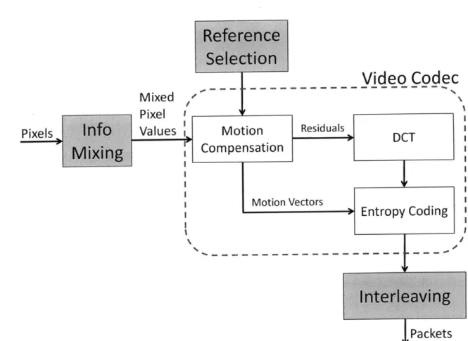
3-1 A Block Diagram of ChitChat's Architecture. The gray boxes
refer to ChitChat's components. The white boxes are typical compo-nents of today's codecs. . . . . 26 4-1 Hadamard mixing spreads the error and produces less jarring
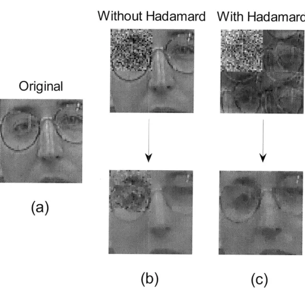
frames. (a) shows the original image (b) shows the image after adding noise to a macroblock and denoising the resulting erroneous block, (c) shows a Hadamard-mixed version of the image after adding noise, un-mixing, and then denoising. The figures shows that Hadamard mixing spreads the noise, allowing the receiver to easily denoise the image. . 31
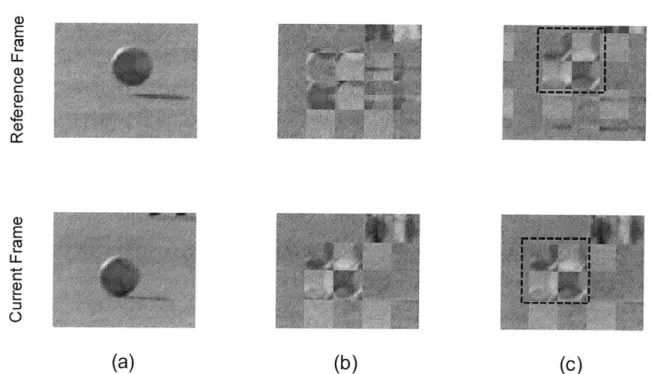
5-1 Challenges with motion compensation. Column (a) shows two
consecutive frames in the pixel domain. The ball has moved from one frame to the next. Column (b) shows the same two frames af-ter Hadamard transform. One cannot see an object that moved across the two frames though the original frames represent a moving ball. Column (c) shows the same two frames with an alternative Hadamard transform where the boundaries of the combined blocks move from one frame to the next, with the moving ball. Now, one can see that the
area in the dashed square moved from one frame to the next. . . . . . 37
6-1 Interleaving the Macroblocks. The macroblocks are interleaved to
ensure that adjacent macroblocks will not be transmitted in the same packet. . . . . . . .. . 46
7-1 Example of the Loss Map of a Frame. Three packets of size 568, 856 and 774 bytes are sent for this frame and the second packet is lost.
White color indicates the corresponding macroblock after the mixing is lost. . . . . . . . . 50
7-2 Error Concealment. (a) is the original image. (b) is the reconstructed
version with ChitChat's error concealment. (c) is the reconstructed version with MPEG's error concealment only. . . . . 51 8-1 Testbed Setup in the Lab. We hide A behind a CLICK router
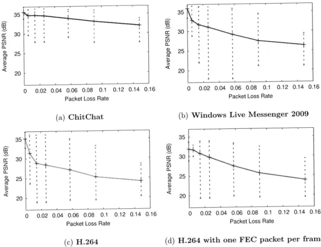
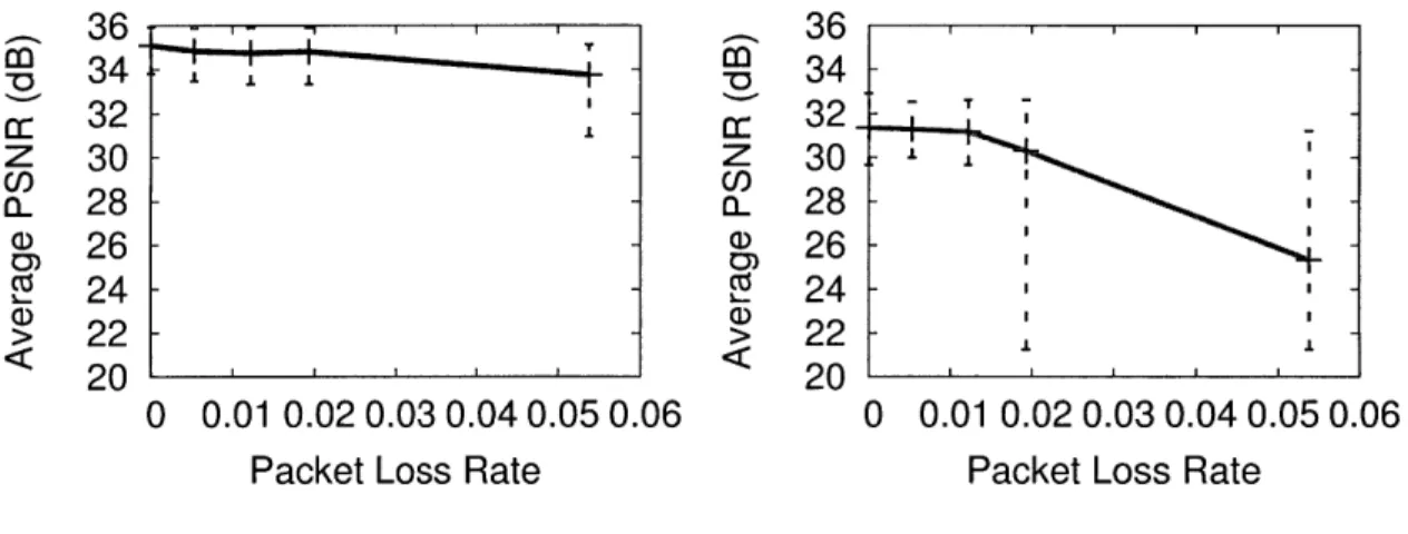
and run Windows Live Messenger video calls between A and B. The competing traffic is all the Internet traffic going from/to A . . . . 59 9-1 PSNR at different loss rate. The figure shows that ChitChat's
video quality is significantly higher than the compared schemes over the whole range of loss rates . . . . 64
9-2 With increased loss rate, FEC shows a cliff effect while ChitChat degrades sm oothly . . . . 66 9-3 PSNR at different loss rates of the testbed experiment. The
figure shows that ChitChat's video quality is significantly higher than that of WLM for the whole range of loss rates. . . . . 67
9-4 A histogram of sender-side outages. These outages are the re-sult of the rate control algorithm detecting the lack of bandwidth and resorting to a very low frame rate. . . . . 68 9-5 Histograms of Loss-Caused Outage Duration . . . . 69 9-6 PSNR of ChitChat with ACK and NACK on the U.S.-China
Link. The RTT on this link is about 300 ms. The blue data is ChitChat
with NACK. The orange data is ChitChat with ACK. . . . . 70 9-7 ChitChat's Contribution to an NACK mechanism on traces
with long RTT. ChitChat reduces the impact of the drifting effect to
a great extent and yields usable decoded frames of PSNR higher than
9-8 Error Concealment when the Estimated Lost Motion Vectors are not Accurate. (a) is the original image. (b) is the reconstructed
version with ChitChat's error concealment. (c) is the reconstructed version with MPEG's error concealment only. . . . . 73
Chapter 1
Introduction
1.1
Is the Internet Ready for the Challenge of
Con-sumer Video Communication?
Video chat is increasingly used for both personal and business communications
[31].
Measurements show a fast growth in video conferencing over Skype, Windows Live Messenger, Google Talk, etc. [14, 61, 11, 7]; and the trend is likely to become stronger with the recent introduction of Apple FaceTime over mobile phones[4].
This interest in video communication shows that, if video chat is made reliable, video telephony may gradually replace audio telephony. Today however, Internet video calls suffer from transient packet loss, which causes frame freezes and poor visual quality [17, 34]. Without better mechanisms for handling packet loss, video chat will not reach its full potential.According to a recent landmark study conducted by Nemertes Research [13], unless service providers invest billions of dollars in updating them, Internet access infras-tructures, instead of cores of the Internet, will be a bottleneck for supporting user demand in the next few years. The exploding visual richness of online communications and entertainment is the main reason for this, and can potentially lead to more delay and congestion experienced by end users. With the rapid advance in technology, this is unlikely a disaster, yet it shows that the Internet today is far from over-provisioned.
Common reasons for packet loss include congestion (long-term) due to lack of abundant bandwidth, wireless loss, and large variation (sudden drop) in bandwidth. While rate adaptation helps prevent the first category of losses from happening, wire-less random loss and loss caused by large variation in bandwidth (common on access links) are inevitable.
Typically a loss rate lower than 5% is considered acceptable for traditional data transmission, however, video applications are particularly extremely intolerant of packet loss, because of the compression done at the source. Packet loss results in jitters, corrupted images and video stalls. Jitters are much less noticeable and much more readily tolerable than the other two. User visual experience is severely worsened
by corrupted images and video stalls. Commercial video chat softwares usually discard
a frame if it is corrupted and no longer a smooth degradation of the original frame. This decision leads to more and longer video stalls. Disruption of communication due to video stall or audio-video out-of-sync is without any doubt the biggest annoyance for video chat users nowadays [17].
1.2
What Distinguish Video Chats from Real-time
Streaming?
While much of the literature has studied the problem of reliable video delivery in presence of packet loss, it often does not distinguish video chat from live video stream-ing [41, 23, 69, 54, 20]. In fact, both applications suffer from significant quality degra-dation in the presence of packet loss. They also both have real-time requirements. Nonetheless, video chat has unique characteristics that set it apart from live stream-ing. Specifically:
* Due to its interactive nature, video chat has much stricter timing constraints than live streaming. While video streaming is insensitive to a start-up buffering delay of tens of seconds [39], the ITU G.114 standard recommends a maxi-mum delay of 150 ms for video calls in order to ensure lip synchronization [49].
Meeting this timing constraint is challenging given today's processing [56]1 and propagation delays2. Hence any additional latency introduced in order to tackle transient packet losses is highly undesirable.
0 Since access link is likely to be the connection with the least available
band-width and hence has the highest probability of packet loss, it has always been the main bottleneck for media transmission both for streaming and interactive applications [3, 12]. However, video chat is more likely to suffer from packet drops at access links than live streaming. Specifically, a video chat application sends video in both directions. Technologies like ADSL and cable modem how-ever have significantly lower uplink speeds than downlink speeds [16]. Currently, most cable plans offer two or three times as much downlink bandwidth as up-link. This design choice is made based on the fact that most users upload rarely compared to their downloads. With the trend that people more and more often share their data (files, photos, videos) with each other, the allocation of up-link/downlink capacity needs to be reexamined, yet it is unlikely to be the case that an efficient design will allocate more or similar overall uplink bandwidth as the overall downlink bandwidth. However, when we make video calls, we use as much uplink bandwidth as download bandwidth, making the uplink a much more sensitive bottleneck for video chat applications.
As a result of these characteristics, solutions for packet loss proposed in the con-text of streaming applications [41, 23, 69, 54, 20] are mostly ineffective for chatting applications.
(a) Forward error correcting codes (FEC): Adding redundant error correction
codes at the sender side has been widely used in conventional data transmission applications without stringent timing constraints. This is a common way to enable the receiver to detect and correct errors due to packet loss or channel noise. In recent 'Usually longer processing time yields better compression and hence more efficient usage of the bandwidth.
2Round Trip Time in the Internet has been reduced tremendously over the last decade. Currently,
most links within north America have an RTT of lower than 50ms; cross-country links' RTT is around 100ms; intercontinental links such as U.S.- China has an RTT of 200-300ms.
years, FEC has been gradually adopted in real-time applications such as streaming, given that the streaming applications can usually allow some start-up buffering as well as tolerating some infrequent buffering during the streaming. This tolerance to buffering allows the application to apply FEC in a way as efficient as in the traditional data transmission applications. On the contrary, FEC codes are inefficient for dealing with transient packet loss in video calls. Typical Internet loss rate is less than 1% [66]. In principle, an FEC code that combines every 100 packets together, adding only one or two packets of redundancy, can recover from such a loss rate. In video chat, however, coding across frames is precluded by the need to play each frame as soon as it arrives, with no extra delay. Coding within a frame requires adding at least a single FEC packet per frame. Yet, each frame in consumer video chat applications
(e.g., Skype) is typically sent using 2 to 5 packets [29].3 Hence, even when the loss rate is as low as 1%, a minimal FEC redundancy of one packet per frame increases bandwidth usage by 20% to 50%. Thus, FEC is likely to increase the loss rate in a congested environment. Indeed, past studies of Skype show that the use of FEC increases the bandwidth overhead by 20% [55] to 50% [29]. In fact, even for IPTV solutions, people have found that "increasing the amount of protection can reduce packet loss to some extent, but the protection capability is limited due to the short time interleaving and the bit rate reductions required to increase the protection could become severe." [52]
(b) Path Diversity: Proposals for routing packets over multiple paths using an
overlay network [1, 21, 20, 44], while effective at reducing packet drops in the core of the Internet, cannot deal with losses on the access links of the communicating nodes. Since the latter losses are common in video chat [55], this approach too is not sufficient for these applications. [22, 36]. In fact, while Skype has an overlay network which could potentially route traffic away from congested points in the backbone, Skype uses a relay node only to traverse NAT boxes or firewalls, and prefers the direct path whenever the nodes are not NAT-ed [22].
3
Skype and Windows Live Messengers, transmit at 200-700 Kbps with an average frame rate of 10-15 fps and an average frame size of 2 to 5 packets [55, 29].
(c) Retransmissions: Commercial video chat softwares try to avoid packet
re-transmissions [22] because such a mechanism requires delaying the received frames and hence interacts badly with the tight timing constraints of video calls. The uni-fication of transmission for video data (streaming with CDN) with traditional data is highly desirable for various communities. Specifically, the adoption of HTTP in one-way streaming is more and more common these days. However, this convergence is unlikely to happen with the case of interactive applications such as video chats or
VoIP, because of the tight timing constraints. In other words, even if reliable protocols
like HTTP are used, the retransmitted packets are very unlikely to be of much use
for interactive video applications. ' 5
1.3
ChitChat: a Video Chat Centric Solution
This thesis presents ChitChat, a new approach for dealing with packet loss in video calls. ChitChat neither requires the receiver to delay a frame, nor introduces band-width overhead. Further it addresses both edge and core losses, especially effective in the cases of short-term transient changes in bandwidth and the resulting packet buffer overflow. Our basic idea is simple. We want to ensure that the information in each packet in a frame describes the whole frame. As a result, even when some packets are lost, the receiver can still use the received packets to decode a smooth version of the original frame. This reduces frame loss and the resulting video freezes and yields a smooth user experience of better perceived video quality. The idea is inspired by intensive work on both multiple description coding and network coding.
To achieve our objective of having each packet describe the whole frame, we mix
4When the caller and the callee are behind port-restricted NAT and UDP-restricted firewall,
Skype is forced to send its media traffic over TCP; and TCP's retransmission mechanism will apply. However, Skype prefers the use of UDP for transmitting its media data as long as it has this option [22]. Windows Live Messenger uses HTTP for its "Show My Webcam" mode, which is indeed
a single-direction streaming mode.
5Retransmitted packets containing important information such as header and keyframes which
later frames depend on might be helpful. However, predicting whether these packets will arrive in time to be of any use or they are simply extra burden on the link during congestion is a challenging task.
the information in a frame before presenting it to the video codec. However, naively mixing the information in each frame destroys the temporal and spatial correlation in the raw video, which the codec relies on for efficient compression. In other words, this destroys the codec's ability to recognize objects as they move across frames, and use this information to compress the video. This long-lasting problem results from the gap between the video community and the networking community. Given the large variety of usages of video, one main ultimate goal of the video research community has always been high compression efficiency. However, when videos start to be sent over a best-effort IP network, the networking community focuses on how to improve reliable transmission of these highly compressed videos. Sacrificing compression efficiency too much to improve received video quality is in no one's favor, given the low loss rate of the Internet today. Ideally, reliable video transmission should be achieved using a minimum overhead in size. In ChitChat, to deal with this issue, we design our information mixing algorithm to be shift-invariant (i.e., a movement of an object in the pixel domain translates into a corresponding movement in the mixed frame). We show that this approach allows existing codecs to continue to work efficiently in the presence of information mixing.
We have implemented ChitChat and evaluated it both on a testbed using a CLICK router to introduce packet loss and over multiple Internet paths, within the U.S. and between U.S. and China. We also compared it with Windows Live Messenger 2009, a popular video chat software
[11],
as well as H.264 and H.264 with one FEC packet per frame. Our results show:" In comparison to Windows Live Messenger, ChitChat reduces the number of
outage events by 15x (from a total of 195 outages to only 13 outages).
" Further, at all loss rates, ChitChat's video quality is higher than that of
Win-dows Live Messenger. Particularly, for loss rates of 1% to 10%, ChitChat im-proves the average video quality (PSNR) by 3 to 6 dB over Windows Live Messenger.
" Finally, in the absence of packet loss ChitChat delivers the same video quality
Chapter 2
Related Work
2.1
Dealing with Packet Loss in Video
Past work has recognized the negative impact of packet loss on video applications [52,
28, 62, 59, 63] and proposed techniques for dealing with the problem [21, 54, 68, 50].
These proposals can be divided into two categories: solutions for Internet-core losses, and solutions for last-hop losses.
2.1.1
Packet Loss at the Internet Cores
Many solutions for dealing with losses in the core of the network employs path di-versity, i.e., different versions of the video are sent over independent paths to avoid correlated drops. For example, in [20], the authors use multiple description coding, and send different descriptions over different paths to the receiver. Due to the self-reliance nature of the descriptions, this design can leverage path diversity to improve the video quality in face of core losses. SplitStream [27] employs multiple distribution trees and splits the load among the nodes while taking into account heterogeneous bandwidth resources. PROMISE [38] uses peer-to-peer delivery, monitors the path to potential peers and dynamically switches between them to improve performance. Approaches that use path diversity to reduce losses are complementary to our design. They however cannot deal with losses on access links, while ChitChat can address
both core and last-hop losses. Moreover, loss occurring on the access link is a much more prevalent problem in video transmission nowadays, compared to loss occurring at the cores of the Internet. It is even worse for video chat since conferencing applica-tions need to transmit video in both direcapplica-tions, yet most end systems have low uplink bandwidth.
2.1.2
Packet Loss On Access Links
Past solutions for losses on the access links are primarily limited to retransmission or forward error correction. Some designs buffer corrupted frames and ask for re-transmission of lost packets [41, 23]. The stringent timing requirement in interactive applications makes retransmissions much less useful than in conventional applications. Also, if retransmitting certain important information is found beneficial, it can always work in parallel with our design and hence will not be the focus of this thesis. Other designs add forward error correction at the sender to allow the receiver to recover from losses without retransmissions [69, 54]. However, as explained in Chapter 1,
FEC is inefficient for today's Internet where the loss rate is usually below 1% [32, 66],
and could potentially be recovered by adding only 1% packet redundancy; yet the fact that video chat has to code over a short block length of 1 frame, increases the redundancy overhead to 20% to 50%.
2.1.3
Multiple Description Coding
Multiple description coding (MDC) has been suggested and extensively studied in the past decade [67, 35]. It is considered as a promising solution for dealing with both In-ternet core losses and access link losses. The goal of MDC is to generate independent descriptions of the same video unit (a video unit can be a frame, a group of pictures
(GOP), or an entire video, depending on the application's timing constraints), so
that a reconstructed version of proportional degree of fidelity can be derived from the received descriptions in the presence of loss. MDC algorithms proposed in recent years can be generally divided into three categories: postprocessing-stage MDC (FEC
based) [57], encoding-stage MDC [67, 64, 46] and preprocessing-stage MDC [65, 70]. FEC-based MDC schemes 1 is not suitable for video chats as explained in Chapter 1. Encoding-stage MDC schemes typically include multiple description quantization, multiple description transform coding and multiple descriptions of the motion vec-tors. One major disadvantage of encoding-stage MDC is the requirement of making significant changes to the video codec. In addition, the high computation complexity of some of these encoding-stage MDC designs eliminates the possibility of their usage in real-time applications [46]. Past work on preprocessing-stage MDC are limited to subsampling-based MDC in spatial, temporal, or frequency domain. These subsam-pling methods disrupt the spatial or temporal correlation in the video sequence and hence result in redundancy. Plus, by simply splitting neighboring frames or pixels, these methods' performance entirely depends on the accuracy of estimating the lost descriptions. In contract, ChitChat's infomation mixing offers error concealment gain even when the motion estimation itself is not accurate. Apart from these unique prob-lems, a lot of the MDC techniques proposed in the past, in all these three categories, produce extra samples to code and hence do not follow the same pattern of MPEG data anymore. Unlike the MDC schemes, our design neither requires changing the video codec, nor produces extra samples for coding, and at the same time, by main-taining the correlation in the video sequence, our design does not introduce overhead in size.
2.1.4
SoftCast
ChitChat's information mixing algorithm is motivated by SoftCast, a recent proposal for wireless video [42]. SoftCast however addresses a different problem: it enables a wireless transmitter to broadcast a video stream that each multicast receiver decodes to a video quality commensurate with its wireless channel quality. SoftCast also re-quires changing both the physical layer and the video codec, while ChitChat works
'FEC-based MDC schemes convert the prioritized output of the codec into unprioritized descrip-tions by adding progressively weaker FEC protection to video information of decreasing importance.
with existing video codecs and physical layers.
2.2
Rate Adaptation
Also related to our work are mechanisms for media rate control, such as TFRC [37],
DCCP [48], and others [45, 18, 53]. These protocols control the transmission rate
to ensure that the sender does not transmit way above the available bandwidth and hence does not cause excessive packet loss. Rate control is complementary to our design; it addresses long term persistent losses, rather than transient losses, which are unavoidable in today's best effort Internet subject to common short-term transient bandwidth changes.
2.3
Performance Study of Commercial Applications
Additionally, the last few years have seen interest in studying the mechanisms in commercial video applications and their performances over the Internet. In particu-lar, [29, 24, 55] study Skype's rate adaptation and reaction to changes in available bandwidth. The authors of [55] also study Windows Live Messenger and other video chat applications. All of these studies however operate at the packet level, looking at throughput and packet loss rate, but do not directly tie these measurements to the corresponding video quality. This is due to the proprietary nature of video chat applications which prevents direct access to the decoded video frames. These studies offer great insights for us.
Chapter 3
ChitChat at a High Level
ChitChat is a video-chat centric approach to deal with transient packet loss in best-effort IP networks such as the Internet. Its design ensures that: 1) received frames can be decoded immediately and displayed, 2) no extra bandwidth is required, 3) the approach works with both edge and core losses, and 4) it works seamlessly with state-of-the-art video codecs.
ChitChat's architecture, illustrated in Figure 3-1, has three components that to-gether improve resilience to lost packets:
o The information mixing module codes a frame content to ensure that the impact of a packet loss is not concentrated in particular corrupted patches, but is rather smoothly distributed over the frame.
o The mixing-aware reference selection module ensures that the video codec can
effectively compress the content in the presence of information mixing.
o The interleaving module distributes the video data into packets in a manner that allows the receiver to reconstruct a smoothly degraded version of a frame from any subset of its received packets.
As the figure shows, ChitChat operates in conjunction with standard codecs (e.g., MPEG-4/H.264), which makes it easy to integrate in existing video chat applications. The following sections describe ChitChat's components in detail.
Video CodeC
Mixed
Pixel
Pixels Info Values Motion Residuals
DCT
MixingCompensation
Motion Vectors Entropy CodingInterleaving
PacketsFigure 3-1: A Block Diagram of ChitChat's Architecture. The gray boxes refer to ChitChat's components. The white boxes are typical components of today's codecs.
Chapter 4
Information Mixing
ChitChat introduces a preprocessing step that mixes the pixel values in each frame before passing the frames to the video codec. The mixing is done using a Hadamard transform
[43].
Hadamard coding has been used in multiple prior systems to smooth out the impact of channel errors. For example, both MIMO systems [19] and Soft-Cast [42] apply a Hadamard-based code to the symbols transmitted over a wireless channel. In contrast, ChitChat applies a Hadamard transform to the pixels directly. Hence, it can operate without changing the physical layer or the video codec. To the best of our knowledge, ChitChat is the first system to show that applying a Hadamard transform to the pixels themselves improves the video quality in the presence of packet loss. In this chapter, we first explain the Hadamard transform, then describe how we apply it in our context.4.1
Hadamard Transform
The Hadamard matrix is an orthogonal matrix whose entries are -1 and 1. In partic-ular, the 4-dimensional Hadamard matrix looks as follows:
1 H=--1 1 -1 1 1 __1 -1 -1 1 -1 -1 1 The Hadamard transformed version of a, b, c, and d is
S1 1 1 1 a
b 1 1 -1 1 -1 b
S 2 1 1 -1 -1 C
d1 -1 -1 1 di
Hadamard transform has the property of evenly distributing corrupted versions of the transmitted values: & + Ca, b+ eb, C+
ea, eb, ec, ed, we can reconstruct the original values as:
b 2 a b C d 1 -1 1 -1 1 2 1 1 -1 -1 ea ea Ca Ca
1 5+
+ Cb + ec + ed - eb +eb - eb - ed - ed +Cdthe error. If we receive
ec, d- + ed, with errors
From the above equation we can see that any error in the transmitted signal & or
b or or d is evenly distributed to the 4 reconstructed numbers.
Hadamard is an orthogonal matrix.)
The two properties above work greatly towards our goal of a smooth degradation in face of loss or error.
* By applying Hadamard, we will be able to distribute the channel noise evenly on the pixels we combine together.
* Quantization noise which results from the lossy compression applied by the codec is still evenly distributed on pixels as if did not apply Hadamard to them.
" The total sum of square error does not change, meaning that given the same
degree of quantization and same amount of loss, the overall quality (i.e., PSNR) of the part of image we are combining will not change.
Said differently, Hadamard distributes the noise resulting from a packet loss over a frame without adding any extra noise. This creates a smooth frame with no jarring corrupted patches. Also when the noise is distributed over a larger area, it tends to become easier to correct using simple denoising algorithms leveraging only local information. 1
4.2
Hadamard Mixing in ChitChat
We apply the Hadamard transform directly in the pixel domain, before any compres-sion. Given a frame, we first compute the average luminance in the frame and subtract it from all pixels. We refer to this average as the DC value in the frame. We pass this value directly to the interleaving component which includes it in every packet for this frame to ensure its most reliable delivery in the face of losses. Removing the DC value before coding images or frames is typical in the literature
[33]
and does not change how the codec works.As in MPEG, we divide the frame into macroblocks, where each macroblock con-tains 16 x 16 pixels. We take every 4 adjacent macroblocks and code them together 'Simple denoising filters are usually just low-pass filters. Since low-pass filters consider only the difference between adjacent pixels, reducing the local noise magnitude generally renders the image easier to smooth by low-pass filters.
using the Hadamard matrix. In particular, consider 4 adjacent macroblocks, A, B, C and D. We represent these macroblocks as follows:
A C a1 a2 a16 C1 C2 a17 a18 a32 C1 7 C18 *' a225 -.. a 226 -.. a 256 -. . C 2 2 5 . . . C 2 2 6 C1 6 C3 2 ' C2 56 b1 b17 b2 b18 b16 b32 di d17 d2 d18 d16 d32
To apply the Hadamard transform on these in each macroblock into a vector, e.g., (ai, a2
,*-H, to combine the 4 vectors:
... a256
... b
2 5 6
-. -6 C56
''' d256
4 macroblocks, we rearrange the values - a256), and use the Hadamard matrix,
- - a2 5 6
-. b
2 5 6
-.-. C256
''' d256
We then rearrange the coded vectors into 4 mixed macroblocks A, B, C, and D. We repeat the process on all non-overlapping sets of 4 adjacent macroblocks in the original frame to produce a mixed frame.
4.3
Effect of Hadamard Mixing on a Toy Example
Video codecs typically code frames as differences with respect to the previous frame (or any chosen reference frame). Thus, when a packet is lost for a frame, after error concealment, most likely we lose the corresponding differences, which leads to some noisy macroblocks. To understand the effect of Hadamard mixing on these losses, let
'. 'b 225 -.-. b226 -. b256 -. -4 225 .. 'd 226 *.*. d256
Without Hadamard With Hadamard
Original
(a)
(b)
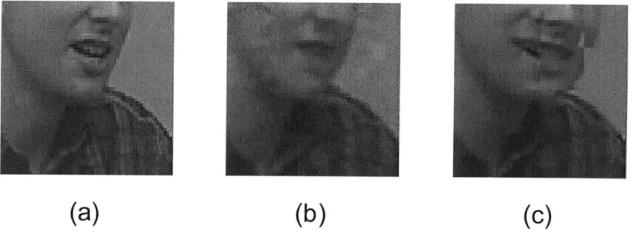
(c)
Figure 4-1: Hadamard mixing spreads the error and produces less jarring frames. (a) shows the original image (b) shows the image after adding noise to a macroblock and denoising the resulting erroneous block, (c) shows a Hadamard-mixed version of the image after adding noise, unmixing, and then denoising. The figures shows that Hadamard mixing spreads the noise, allowing the receiver to easily denoise the image.
us consider the toy example in Fig 4-1. Specifically, we take an image, corrupt one of its macroblocks, and observe the impact of corruption, with and without Hadamard mixing. Figure 4-1(a) shows the original image; whereas the top row in Figures 4-1(b) and 4-1(c) shows the image after adding random noise for the cases with and without Hadamard mixing. (The noise is Gaussian with a mean of 0 and a standard deviation of 40. These parameters are set to produce noise magnitudes comparable to what we see due to packet losses in our experiments.)
Then, we try to recover the original image by denoising. Denoising filtering is rec-ommended by MPEG-4 in post-processing [581. Here we use a simple smoothing filter which only operates on adjacent pixels. For the Hadamard-mixed image, however, we first invert the Hadamard transform before applying denoising. The results after denoising are shown in the bottom row in Figures 4-1(b) and 4-1(c). As can be seen from the figures, the errors with Hadamard-mixing look less jarring, which shows the benefit of applying Hadamard.
Note that the error we will see due to packet loss will not, in general, be random Gaussian noise; and will depend on the lost information. But as we show in Chapter 7, the general effect of Hadamard continues to spread the noise and deliver a better video quality.
4.4
Why Not Use a Bigger Hadamard Matrix
One may wonder why we do not combine more macroblocks together, instead of just four. Isn't it even better if we can distribute the noise across a wider range of blocks (a larger area)? The answer is mainly twofold." As explained in Chapter 1, in video chat one should code only within a frame
to ensure that each received frame can be immediately decoded and displayed. However, the average size of a frame in off-the-shelf video conferencing programs (e.g., Skype, Windows Live Messenger, etc.) is 2-5 packets [55]. Hence, there is no point mixing more macroblocks.
to pass to the video codec corresponds to the number of macroblocks mixed together, and hence mixing too many macroblocks can increase the complexity unnecessarily.2
2There is another subtle reason, which is the flexibility of motion compensation. One can imagine
combining all the macroblocks in a frame. The block motion compensation of the mixed frame will be almost equivalent to global motion compensation of the original image.
Chapter 5
Mixing-Aware Reference Selection
5.1
Motion Compensation in Video Compression
Video codecs (e.g., MPEG-4/H.264) exploit correlation across frames to compress the video. They do so by encoding a frame with respect to a prior frame, called a reference frame. Specifically, for each block in the current frame, the codec finds the closest block in the reference frame, where the distance is typically computed as the sum of square errors [60]. The codec computes a motion vector that represents the vertical and horizontal shifts between the block and its closest reference block. It then encodes the current block using the differences from its closest reference block and
the motion vector. This form of compression is called motion compensation.
Motion compensation is the most expensive but also the most valuable step in achieving compression in state-of-the-art video codecs. A lot of work has been ded-icated to finding faster, more flexible or more efficient motion search algorithms. Allowing more flexibility in motion compensation in general means expanding the motion search area, increasing the number of reference frames, and reducing the size of the base unit that the codec performs motion compensation on. More often than not, more flexibility results in more bits spent on motion vectors and less bits spent on encoding the residual. Deciding the optimal degree of flexibility has always been a difficult problem in video coding. Yet it is not the focus of this thesis. In our design, our goal is to allow the same degree of flexibility as the base video codec decides to
use. The typical block size for motion compensation is 16 x 16 pixels, meaning that the codec finds a close match for each non-overlapping 16 x 16 block in a frame. MPEG-4 however has the option of using different block sizes depending on the amount of motion in the video. In video conferencing applications, the background is often rel-atively static and we expect slow/medium motion except for the speakers' faces and gestures. So in the prototype we built, we only implemented 16 x 16 block size, al-though all of the MPEG-4 sizes can be easily incorporated in our algorithm once we have the auxiliary reference frames as we will describe later in this chapter.
5.2
Obstacles in doing Motion Compensation after
Information Mixing
One cannot naively give the codec the sequence of Hadamard-mixed frames and expect motion compensation to continue to work as if the frames were not mixed. Figure 5-1 illustrates this issue. The first column in the figure shows two consecutive frames in the pixel domain. The ball has moved between the two frames. Thus, the codec can compress the current frame simply by representing the macroblock with the ball as a shifted version of some block in the previous frame. The middle column in the figure shows the same two frames after Hadamard-mixing. It is no longer the case that one can see an object that moved between the current frame and the previous frame. Thus, if we simply give the codec the sequence of Hadamard-mixed frames, motion compensation would fail in finding how a block moved across frames.
Luckily however the way we apply the Hadamard transform is shift invariant as will be proved. That is if an object shifts position in the original pixel domain, it will also shift by the same amount after the Hadamard transform. One may then wonder how come the two Hadamard-mixed frames in column (b) in Figure 5-1 do not show a moving object? The reason is simple: It is because the boundaries of the blocks over which we perform the Hadamard transform do not shift with the moving object. Figure 5-1(c) shows an alternative Hadamard transform of the original frames in
E U-) U4) (D E U_
(aL())c
Figure 5-1: Challenges with motion compensation. Column (a) shows two con-secutive frames in the pixel domain. The ball has moved from one frame to the next. Column (b) shows the same two frames after Hadamard transform. One cannot see an object that moved across the two frames though the original frames represent a moving ball. Column (c) shows the same two frames with an alternative Hadamard transform where the boundaries of the combined blocks move from one frame to the next, with the moving ball. Now, one can see that the area in the dashed square moved from one frame to the next.
Figure 5-1(a) where we move the boundaries of the Hadamard-combined blocks with the moving ball. These frames show a moving block, and hence are easily compressed
by today's codecs.
The above argument shows that one can perform effective motion compensation if one computes the Hadamard transform over all possible shifts of the macroblocks. Even if we assume that object movement between frames stays within a limited area, and hence limit our search, similarly to MPEG, to an area of -16 to 15 in both the x and y coordinates, there are 1024 candidate shifts for the Hadamard transform. Given a typical frame size of 240 x 320 and a block size of 16 x 16 we need to do Hadamard transform 240 x 320/16/16 x 1024 = 307, 200 times for each frame. this
overhead is unacceptable.
This problem, however, can be solved with a negligible computation overhead. The key insight is that there is a huge amount of shared information between these shifted Hadamard-transformed blocks. In particular, since these shifted blocks that we need to calculate Hadamard transform on share a great number of pixels and our mixing is shift invariant, we can perform the computation for each pixel once and reuse it in all these blocks, and thus significantly reduce the overhead. Below we explain our algorithm which exploits this insight.
5.3
Algorithm
Let's define the 4 adjacent macroblocks we are working on as:
A B C D A = F (4m : xo + 15, yo : yo + 15) B = F (mO + 16: :rO + 31, yo : yo + 15) C = F (mo : zo + 15, Yo + 16: yo + 31) D = F (mo + 16 : xO + 31, yo + 16: yo + 31)
After the Hadamard transform we have:
A B A B
= H
C D C D
Let frame R be the reference frame for frame F. Many codecs use the previous frame as the reference frame. However, our algorithm can work with any reference chosen by the codec. And in 5.4, we will discuss the impact of different choices in selecting reference frames.
in the following way. RA(x, y) = [R(x, y) + R(x + 16, y) + R(x, y + 16) + R(x + 16, y + 16)] 21 Ra (x, y) = - 16, y) - R(x, y) + R(x - 16, y + 16) - R(x, y + 16)] 2 1 R(x
y)
[R(x,y
- 16) + R(x + 16, y - 16) - R(x,y)
- R(x + 16,y)]
1 Rb(x, y) = I[R(x - 16, y - 16) - R(x, y - 16) - R(x - 16, y) + R(x, y)] 2When the pixel is out of range, e.g., x - 16 < 0, we use the boundary pixel.
Given the above auxiliary reference frames, motion compensation on Hadamard-mixed frames requires only a minor tweak on motion compensation in the pixel do-main. Specifically, without information mixing, given a macroblock in frame F, the codec would search an area of width r, and height ry in the reference frame R, looking for the closest block. However, with information mixing, the codec treats each one of the mixed macroblocks slightly differently. When it searches for a closest repre-sentation of A in the reference, the codec searches in the neighboring region in the auxiliary frame RA. Similarly, to find the prediction for B, it searches in Rh; in Ra to find a prediction for C; and in Rb to find a prediction for D.
This approach effectively solves the boundary issues discussed earlier. In particu-lar, because of fixed boundaries, a pixel which would have been in A in the original frame could end up in some B in the reference frame, in which case motion compen-sation would fail to find how a block moves across frames. To address this issue, our algorithm essentially removes these boundaries in the reference frame by computing the four auxiliary frames. Thus, we create auxiliary reference RA, which has only the
A transform, auxiliary reference Ra3 which has only the B transform, and so on. We
can then perform motion compensation for each of these blocks by searching in the corresponding reference frame. 1
'By shifting in RA, we are essentially doing motion search in the original reference frame R,
because the A in
Note that once the four auxiliary frames are computed, the search for the closest block has the same complexity as in the case without information mixing. This is be-cause, for each Hadamard-mixed macroblock, the codec needs to search only a single auxiliary reference frame (RA, R3, Rb or Rb). The time for computing the auxiliary
frames themselves is relatively small in comparison to the motion search, which re-quires exploring all possible pixel shifts, and is known to be the most computationally expensive part of today's codecs [601.
Finally, after motion compensation, today's codecs encode the residuals using 8 x 8 two dimensional DCT, order the 64 DCT coefficients in zigzag order, and use entropy coding to encode the motion vectors and DCT coefficients [60). With ChitChat, these steps proceed without modification.
5.4
Intra-coded Frames and Reference Frame
Se-lection
5.4.1
GOP: Group of Pictures
Video codecs occasionally send frames that are coded independently without any reference frames. These frames are called I-frames. In MPEG, as we have described in previous sections, temporal dependency in the video is explored to reduce the compressed video size. Specifically, a group of successive pictures (GOP) are coded together. The first frame of a GOP is an I-frame (intra-coded frame), followed by P-frames (predictive-coded P-frames) or B-P-frames (bidirectional-predictive-coded P-frames). P-frames contain the motion compensation difference information, i.e. motion vectors and residual coefficients, from the previous I-frame or P-frame. B-frames are both forward and backward predicted. In other words, B-frames are coded based on both
is exactly
RA(x: x + 15, y: y + 15).
The function R(xi : x2, yi : y2) returns the pixel values in the area that lies horizontally between xi
and x2 and vertically between y1 and y2 in frame R, and similarly for RA. Therefore, searching for
the previous I-frame or P-frame and the succeeding I-frame or P-frame. Clearly, en-abling B-frame usage will lead to a delay in the video application, and therefore is not suitable for interactive applications, such as video conferencing.
In a GOP starting with an I-frame followed by N P-frames, if the ith frame is corrupted due to packet erasure or channel noise, later frames are all affected. The encoder will always encode the next frame based on the assumption that the decoder gets all the information it sends before and the decoder always accurately knows what the reference frame is. When loss happens and the decoder fails to get (part of) a frame, the encoder and decoder will have different perceptions of the reference frames used for later frames. This is known as a drifting effect or mismatch between the encoder and decoder. 2
In general, error in a frame will propagate to all the frames after it in the same
GOP, and it only stops at the border of this GOP. We can think of the beginning
of every GOP (or the usage of every I-frame) as a resynchronization between the encoder and decoder. A shorter GOP implies a more robust system, but a larger size because I-frames are much larger in size than P-frames. Adaptive GOP size has been suggested and adopted (Skype) in both literature and real systems. In video chat, I-frames are infrequent since there is rarely a change of scene, and hence coding with respect to a prior frame is significantly more efficient than introducing an independent frame. In fact chatting programs tend to introduce an I-frame every 300 frames [30]
or whenever loss is detected.
From the perspective of ChitChat, I-frames can be regarded as frames whose reference is an all-zero frame. With this representation, our description applies to I-frames as well. Since the estimation of channel quality and the selection of proper GOP size is not an easy task, in our design, we get rid of the notion of GOP and take a different approach by using acknowledgment.
2
Intra-coded blocks are used in P-frames when the motion is huge, or periodically with some probability to improve robustness. These blocks will not be affected by errors in previous frames in the same GOP. However in a video conferencing environment with slow/medium motion, usage of a large number of intra-coded blocks will result in a much larger size.
5.4.2
ACK or NACK?
An acknowledgment system is a natural way of synchronization of the encoder and the decoder in a video chat system. Moreover, commercial video chat applications already leverage acknowledgments for rate adaptation. Positive acknowledgment (ACK) and negative acknowledgment (NACK) are two forms commonly used in video chat.
" In a positive acknowledgment (ACK) system, the encoder will encode the
cur-rent frame using ONLY the acknowledged frames as candidate references, not necessarily the immediately proceeding frames. And it explicitly lets the de-coder know which reference frames it used as part of the header information. Whenever the decoder successfully decodes a frame (receives all the packets for the frame), it sends back a positive acknowledgment message (ACK) indi-cating the most recent frames it decoded. The decoder reference frame buffer can delete any frame earlier than the latest reference frames the encoder uses. And the encoder will discard any frame in its reference frame buffer prior to the latest acknowledged frames. 3 In an ACK system like this, the encoder and decoder are always synchronized completely at any moment. In other words, the decoder always has the reference frames the encoder uses to encode each frame; the encoder always knows what frames the decoder has in its reference frame buffer.
* Instead of using only ACKed frames as reference to ensure 100% synchroniza-tion, an alternative is to let the sender always use the immediately preceding frames as reference. When the decoder finds loss has occurred during trans-mission, it can send back a negative acknowledgment (NACK) to let the sender know what information is missed by the receiver. This negative acknowledgment message can be repeatedly sent many times to ensure the sender gets it. Such a
NACK system makes sure that the drifting effect lasts no longer than the time
for the sender to get the NACK message and resynchronize the encoder with
3
In this framework, we eliminate the notion of GOP and I-frames (except for the very first frame
of the video). Every frame is coded with respect to some reference frames. Of course intra-coded blocks are still allowed when motion is large.
the decoder then.
In cases of short RTT, a NACK system is effectively the same as an ACK system. In cases of long RTT, there is a trade-off between robustness and video size. The advantage of an ACK system is that the encoder and the decoder are always syn-chronized and hence the drifting effect is completely eliminated and there is no error propagation across frames. However, this robustness comes at a price of the increase in video size. The gap in an ACK system between a frame and its reference frame is larger than one RTT, because the sender only uses acknowledged frames as reference frames. The larger the gap is, the less temporal correlation there is between a frame and its reference frame. Since the codecs rely heavily on motion compensation across frames to achieve compression, this reduction in temporal correlation translates to increase in the compressed video size. In contrast, always using the previous frame as the reference frame, a NACK system requires less bandwidth than an ACK sys-tem, when no loss occurs. This difference in video size depends on the RTT, as will be shown in Chapter 9. When loss occurs, it takes one RTT for a NACK system to resynchronize. Hence the disadvantage of a NACK system is that it is more vul-nerable than an ACK system when the RTT is large. In a nutshell, in cases of long RTT, using an ACK system guarantees robustness yet results in a larger size; using a NACK system does not introduce overhead in size but it suffers for one RTT when loss happens.
Considering the trade-off between robustness and video size, one should decide whether to use ACK or NACK based on the RTT and the loss rate of the channel. Different chatting programs use different algorithms to make this decision. ChitChat can leave this decision to the video codec and work with both ACK and NACK designs. However, in our implementation and evaluation, we use a NACK design if not stated otherwise. One thing to note here is that, with ChitChat's information mixing and error concealment, the degradation of the visual experience during the drifting effect in a NACK design is ameliorated to a great extent as shown in Chapter 9.
Chapter 6
Interleaving and Packetization
After the codec is done compressing the video, for each mixed macroblock, it produces a motion vector and quantized DCT coefficients. Next, the macroblocks (with their motion vectors and DCT coefficients) need to be distributed into packets.
In current off-the-shelf video conferencing software, e.g. Skype, Windows Live Messenger, Google Talk, only a few packets are sent for each frame in the video. From our experiment, we see an average packet size of about 700 bytes and 2-5 packets are sent for each frame of size 240 x 320. This means each packet contains the information for approximately 100 macroblocks. Without interleaving, adjacent macroblocks, A, B, C, and
b,
will be transmitted in the same packet, which renders the goal of distributing error in a frame impossible.Given that our algorithm enables distribution of the error among adjacent blocks, we certainly need interleaving to put the information for A, B, C and D in different packets. Further, given the bursty nature of packet loss in the Internet, we would definitely want to put the information for A, B, C and D in packets as far away from each other as possible.
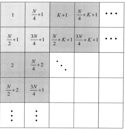
Thus, we use an interleaving matrix to reorder the macroblocks in one frame, as shown in Figure 6-1. Each cell in the graph represents one mixed macroblock. The number in the cell is the new position of the macroblock in the order after interleaving.
N is the total number of macroblocks in the frame. K is the number of 32 x 32-size
Figure 6-1: Interleaving the Macroblocks. The macroblocks are interleaved to ensure that adjacent macroblocks will not be transmitted in the same packet.
colors. The idea is to put A, B, C and D as far away from each other as possible in the new order. Since there are N macroblocks in the frame, we perform interleaving so that A, b,
o
and b have a minimum gap of 4 in the transmitting order. For example, A of the upper-left-most 32 x 32-size block will be the first in the new order after interleaving; b will be the N + lh; C will be the + 1h; b will be the + 1thAnd as we move on to the next 32 x 32-size block, we can put the A of this block in the position after the A of the previous block, which will be the second in the transmitting order.
This interleaving order ensures that information for A, B, C and D is placed as far away from each other as possible in transmission, which means A, B, C and D will end up being transmitted in as many different packets as possible, even if the application is unaware of how the encoded video will be packetized later.