HAL Id: hal-00371596
https://hal.archives-ouvertes.fr/hal-00371596
Submitted on 29 Mar 2009
HAL is a multi-disciplinary open access
archive for the deposit and dissemination of
sci-entific research documents, whether they are
pub-lished or not. The documents may come from
teaching and research institutions in France or
abroad, or from public or private research centers.
L’archive ouverte pluridisciplinaire HAL, est
destinée au dépôt et à la diffusion de documents
scientifiques de niveau recherche, publiés ou non,
émanant des établissements d’enseignement et de
recherche français ou étrangers, des laboratoires
publics ou privés.
Introducing Simulation and Model Animation in the
MDE Topcased Toolkit
Benoit Combemale, Xavier Crégut, Jean-Pierre Giacometti, Pierre Michel,
Marc Pantel
To cite this version:
Benoit Combemale, Xavier Crégut, Jean-Pierre Giacometti, Pierre Michel, Marc Pantel. Introducing
Simulation and Model Animation in the MDE Topcased Toolkit. 4th European Congress EMBEDDED
REAL TIME SOFTWARE (ERTS), Jan 2008, Toulouse, France, France. http://www.erts2008.org/.
�hal-00371596�
Introducing Simulation and Model Animation in the MDE
Topcased
1Toolkit
B. Combemale
1, X. Crégut
1, J.-P. Giacometti
2, P. Michel
3, M. Pantel
11: IRIT- ENSEEIHT, 2 Rue Charles Camichel, 31071 Toulouse
2: Airbus France, 316 Route de Bayonne, BP A0821, 31060 Toulouse Cedex 03 3: ONERA, 2 Avenue Edouard Belin, BP 74025, 31055 Toulouse Cedex 04
1
Abstract:
The Topcased project aims at developing a modular and generic CASE environment for model driven development of safety critical systems. Model validation is a key feature in this project and model simulation is a major way for validation.
The purpose of this paper is to present the current Topcased process for building model simulators and animators. After introducing the functional requirements for model simulation and animation, it is explained how simulation is currently being integrated in the Topcased environment, presenting the main components of a simulator: a model animator, a scenario builder and a simulation engine. The approach is illustrated by the presentation of the first simulation experiment conducted in the project: the UML 2 StateMachines case study.
Keywords: Topcased, model simulation, animation,
Model Driven Engineering, UML 2 StateMachines.
1. Introduction
The work presented here is part of the Topcased project (“Toolkit In OPen source for Critical Applica-tions & SystEms Development”) a project of the French “pôle de compétitivité Aerospace Valley”, dedicated to aeronautics, space, and embedded systems. The Topcased project [1] aims at defining and developing an open-source, Eclipse-based [2], modular and generic CASE environment. It provides methods and tools for the developments of safety critical embedded systems. Such developments will range from system and architecture specifications to software and hardware implementation through equipment definition.
Topcased relies on Model Driven Engineering (MDE) technologies both for building system models and for building the CASE environment itself. Model valida-tion and verificavalida-tion (V&V) is a key feature in Topcased. For validation purpose, one must be able to simulate the dynamic behaviour of the system and to obtain execution traces. For verification purpose, one must be able to check that a system ensures correctness properties and if not, to produce an execution trace which illustrates the fact that the
property is not ensured. The user must then be able to browse these traces in order to validate the dynamic behaviour and understand the property check failures using a model animator.
The MDE technology used in Topcased for defining and tooling modelling languages is centered around the Ecore metalanguage (from EMF: the Eclipse Modeling Framework [3]) and configuration models [4] which are taken as inputs by generative tools (e.g. graphical editor generation).
The purpose of this paper is to present and explain the Topcased process for building model simulators and animators [5, 6].
Section 2 recalls the three main constituents of simulations: workload generation (limited here to the building of scenarios), model execution or animation and results analysis. Then, it focuses on discrete event simulations, the kind of simulations that will be tackled in Topcased, and mentions some existing tools supporting such simulations.
Section 3 introduces the functional needs for model simulation and animation in the context of Topcased, covering the main constituents of simulations. Section 4 describes the first simulation experiment conducted in the project, i.e. the UML 2 State Machines case study, and illustrates it by a small example.
Section 5 explains how simulation has been integrated in the Topcased environment. It first shows what should be defined to complete the definition of a DSML (Domain Specific Modelling Language). Then, it presents three main tools, a model animator, a scenario builder and a simulation engine which compose the general architecture of the simulator. Afterward, it presents the currently available prototype of the UML 2 State Machines simulator.
Finally, the conclusion section proposes short-term perpectives on model animation in Topcased.
2. Simulation: needs and approaches
2.1 Purpose of a simulation
The purpose of a simulation is to gain understanding on a system without manipulating the real system, either because it is not yet defined or available, or because it cannot be exercised directly due to cost, time, resource or risk constraints. Simulation is thus performed on a model of the system.
A simulation is generally defined through three steps (figure 1). The first one consists in generating a representation of the workload, i.e. the set of inputs, to be applied to the studied system. This represen-tation may be a trace (or scenario) depicting a real workload or a synthetic workload artificially gene-rated by heuristics or stochastic functions. The second step concerns the simulation that is performed by applying a workload on a model of the system and producing results. Finally, the third step consists in analyzing simulation results in order to acquire a better understanding of the considered system.
Figure 1: The 3 steps of a simulation
These three steps may be separated and supported by different tools, like a scenario builder (as a workload generator), a model execution engine and result analysis tools. It is also possible to combine in the same tool two of these steps or even the three of them. For instance, it is possible to interactively create a trace while the model is executed. It is also possible to couple the execution engine and analysis tools to present, “on the fly” (i.e. during a simulation), synthetic appropriate results.
Topcased proposes an open source and perennial alternative to modelling and simulation tools. Topcased relies on the Eclipse platform [2] and MDE technologies such as EMF, GEF, GMF [3,4], Acceleo, ATL, Kermeta, OpenArchitectureWare and others. Simulation facilities will allow the Topcased user to execute his models in order to check whether they conform to his expectations.
Currently, modelling languages considered in Topcased mainly focus on discrete synchronous or asynchronous models. A discrete event computation model can thus be used for the model execution. In order to see whether the models behave as expected, the user will run a model animator that
uses the results of the model execution. So, in the Topcased context, simulation will be mainly a means to debug models and validate user requirements. 2.2 Discrete Event Simulations
In the simulation of discrete systems, the simulated time is a discrete virtual time. Two mechanisms are considered for the evolution of discrete time:
• a clock-based (or periodic, or fixed-increment time advance) approach: time move forward in the model in equal time intervals,
• an event-based (or next-event time advance) approach: the model is only examined and updated when an event occurs (or when the system state changes); time moves from event to event.
The traditional modelling formalisms are based on mathematical foundations and largely preceded the advent of computers. Two kinds of representations have been proposed to model discrete systems [7]: • The “Discrete Time System Specification”
(DTSS) has been proposed to model systems that operate on discrete time base, such as automata. Time evolution is clock-based (periodic) in this representation.
• The “Discrete Event System Specification” (DEVS or DE) appeared more recently and was defined for computer-based simulations. It offers an event-based approach more easily managed by an executable program than by a pure mathematical model.
Thus, we have two main paradigms to model the dynamics of discrete systems: the discrete periodic (DTSS, also named “synchronous”) and the discrete event-based (DEVS or DE, also named “asynchro-nous”) formalisms.
These formalisms allow to design modular and hierarchical models. A modular and hierarchical construction consists in coupling existing models in order to build larger models of systems. These formalisms are closed under coupling, which means that a coupled model can be treated as a basic component, i.e. reused like a basic component in other compositions.
2.3 Existing simulation support frameworks
Several tools support Discrete Event simulations. Let us mention, among the more popular ones: Matlab/Simulink, Scilab/Scicos, Ptolemy II, Hyper-formix Workbench, Sildex, StateMate and Uppaal. The two first ones are mainly dedicated to simulation of physical systems with continuous time models, but they offer some capability to support discrete event features, like the “Stateflow” module in Matlab/ Simulink framework.
Model execution engine Workload
generation Analysis Results
Animation
display Results display
often: a scenario (or trace) builder
It is quite difficult to interface these tools with the Topcased environment, i.e. to directly use one of these tools to simulate and animate a model defined with a Topcased editor. Nevertheless, it is interesting to analyze their main characteristics and to point out the most useful features for Topcased users.
As first simulation experiments in Topcased are devoted to the animation of state-transition based models, we carefully studied the functionalities of Sildex, StateMate and Uppaal tools in the previous RNTL COTRE project. These tools, based on simple or timed automata, provide graphical visualization of simulations highlighting active states and firable transitions, coupled with means to visualize and record execution traces.
Another source of inspiration was the Ptolemy II framework developed at Berkeley University [8]. This framework supports heterogeneous modelling, simulation, and design of concurrent systems. Simulation models are constructed under models of computation (or domains) that govern the interaction of the components in the model. The choice of a domain depends on the type of model being constructed. After about 10 years of existence Ptolemy II is a rich and reasonably mature tool, at least for the most important domains, among then the Discrete-Event (DE) domain.
Ptolemy II is component-based and models are constructed by connecting a set of components and have them interact under a domain. In the Discrete-Event domain, components communicate via sequences of timed events. An event consists in a value and time stamp. Components can either be processes that react to events or functions that fire when new events occur. The DE domain gives a deterministic semantics to simultaneous events. The efficiency of a tool during simulations and ability to integrate it in an industrial process should be an important criterion when choosing the more adequate tool. But, as they interpret graphically designed models, all these tools more or less lack in efficiency. That point leads to use them as prototyping tools rather than deploying them in ultimate simulation solutions. Thus, a simulation tool is used to quickly and efficiently design a first model and to conduct simulation experiments to improve and validate the model. Once confirmed, this model can be translated in a programming language (e.g. in Java), and coupled with a kernel supporting Discrete Event semantics, to perform efficient simulations.
3. User requirements for model animation
In the context of Topcased, simulation aims at validating high level domain specific models. Thus, simulation mainly provides a means for the designer to animate his/her models in order to have a better understanding of them and to validate with the user
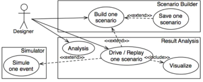
its requirements. The animation may be performed either interactively or driven by a predefined scenario. The main requirements are summarized on the use case diagram of figure 2 and are detailed in the next paragraphs. Of course requirements are described from the user viewpoint. Nevertheless, we have tried to separate concerns. We first describe how a scenario may be described and used to drive the model animation. We then explain how the user may control the animation. Finally, we give requirements about tools to help the user in interpreting the animation results either to visualize effects on the model or to analyse results.
3.1 Scenario builder
A scenario is defined as a sequence of input events occurrences. An event occurrence is defined by its occurrence time and its related information that may include one or several elements of the simulated model. In the case of the animation of an UML2 state machine, we have only one kind of user event that consists in injecting one signal. The target element is the state machine receiving the signal and the associated information is the UML2 signal.
The term “scenario builder” describes any tool that helps building a scenario. The user while animating the model may build a scenario interactively. A scenario may also be built before animation starts. For example, it may be generated from requirements to validate the model being designed or produced by dedicated tools such as a random scenario builder, a model-checker that exhibits a counter-example or a test generator.
Figure 2: Use case of the simulation 3.2 Model animator
Animating a model consists in interpreting each event to make the model evolve accordingly. The effect of one event on the model is defined in the execution engine that follows the semantics of the model.
Figure 3: Subset of UML2 StateMachines handled in model animator Defining the semantics of a DSL is the task of the
language designer not of the model designer. Nevertheless, the model designer may be solicited during animation in order to resolve some non-deterministic choices. For example, he should be able to choose which transition will be fired on a non-deterministic automaton. Heuristics may also be defined in order to resolve such non-determinism. Furthermore, the model designer should be able to control the animation through a set of commands similar to those found on a music or video player, or on a program debugger. During animation, different views (discussed in the next section) may be activated and must be updated as the model evolves. A tool providing this functionality is called a “model animator” and should allow a user to:
• load a predefined scenario;
• play the scenario step by step (event by event); • play automatically: the next step is automatically
triggered when an amount of time is elapsed. It also includes the ability to pause and resume the animation;
• restart the execution from the beginning or stop and exit the animator;
• go forward/backward one step, several steps, to the beginning or the end of the animation or to a certain point (condition on the model, occurrence of an event, previously defined break-point, etc). It may also be useful to be able to inspect the animated model, either textually or graphically as discussed in the next section.
Finally, we should note that it is possible to integrate in the same tool the interactive scenario builder and the model animator. It thus provides the user with one unique interface to build his scenario and inspect the evolution of the model according to the scenario.
3.3 Simulation visualization
The term “simulation visualization” encompasses any tool that provides the user with feedbacks on the execution.
One obvious way to provide the user with feedbacks on the animated model is to display its current state. To do that, one needs to represent some additional dynamic information by extending the graphical notation (graphical concrete syntax) used to edit or visualize the model.
The use of colours or classical graphical compo-nents (such as progress bars, gauges or lights) used as decoration on the model graphical representation may be useful to represent the state of model items. For example, when executing a state machine, current states and firable transitions may be emphasised by displaying them with specific colours. A gauge may indicate the number of received signals.
To provide the user with a better understanding of the execution, it may be useful to define specific panels that aggregate information of the model or to display the state of some model elements according to time (e.g. with a chronogram).
Specific visualization may represent a real interface for the DSL domain. For example, the visualization
panel could represent the set of instruments that are present in the cockpit of a real aircraft.
3.4 Simulation analysis
Simulation analysis looks like execution visualiza-tion. The main difference is that visualization during an execution relies on the user to interpret what he sees, while an analysis tool should provide the user with an interpreted result. For example, analysis tools can verify that an output trace is well formed or that it fulfils some properties.
Simulation analysis tools may be coupled with the execution engine in order to explore all performed executions and determine whether some property holds on the system for these executions.
4. Case study: UML2 state machines
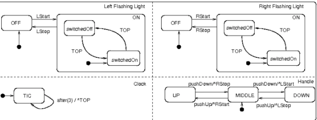
Model animation has first been experimented on UML2 state machines [9] for models that conform to the UML2 metamodel used by the Topcased graphical editor (based on the Eclipse UML2 plugin [10]). However, for the first version of the animator, we have targeted only a subset of the UML2 state machines whose metamodel is shown on figure 3. This metamodel describes the structural properties of state machines. In order to clarify their presentation, we use an example to introduce the concepts that are taken into account for the simulation. The example is shown on figure 4. It consists in a unique state machine because currently the animator is only able to simulate a single state machine. The next paragraph describes the example and points out the UML2 concepts that are handled in the simulation and thus present on metamodel (figure 3). These concepts are put in brackets. The state machine (StateMachine concept) on figu-re 4 models vehicle flashing lights. It is a concurfigu-rent state machine composed of four regions (Region), one for the left flashing light, one for the right flashing light, one for the handle and the last one for an internal clock. Left and right flashing lights share the same state machine and could have been
considered as two instances of the same class FlashingLight describing through a single state-machine the behaviour of a flashing light. But, because we do not address classes and their instances yet, we have to duplicate the state-machine and rename the signals (Signal) that trigger (Trigger) the transitions (Transition). So, the Lstart signal starts the left light and put it in the composite state called ON. It is composed of exactly one region that consists in two substates switchedOff and switchedOn that indicates whether the light is off or on. The light swaps between these two states accor-ding to the TOP signal generated by the clock state-machine. Finally the handle reacts to the user signals pushUp and pushDown and according to its position (down, middle or up) starts or stops the left or the right light.
We only consider local transitions (Transition), i.e. transitions whose source and target states belong to the same region. Transitions are triggered by events (Event) and may execute an activity when they are fired. Activities (Activity) are decomposed into actions. The only action (Action) that is currently handled is the BroadCastSignalAction that broad-casts a signal. An event is either a SignalEvent that corresponds to a specific signal or a time event (TimeEvent) that is related to the time. The transition in the clock region defines a time event indicating that the transition will be fired 3 time units after the state has been entered. The transitions on the handle region are triggered by a signal (either pushUp or pushDown) and, when fired, execute an action that broadcasts the signal that will make the flashing lights regions evolve.
Nevertheless, all the elements that are not taken into account for the simulation may be present in the model but are ignored. An audit using OCL constraints must be established to warn the user of the unsupported elements (and the possible failure in the simulation).
5. Integration of simulation into Topcased
In this section, we describe how simulation has been integrated in Topcased. The main requirement about simulation is the ability to animate a model that has been defined using a Topcased generated editor. The purpose of the simulator is then to animate the model so that the user may be able to validate it. We thus favour interactive simulation and a discrete event model of computation. Despite these choices, most of our proposition is general enough to be applied on a non interactive simulation with other models of computation.
In Topcased, we consider that the starting point is the definition of the DSL metamodel and the existence of a graphical editor built using Topcased facilities. Unfortunately, this information is not enough to animate a model. So we first describe what should be defined to complete the definition of the DSL. Then, we describe the general architecture of the simulator that relies on three main tools, an animator, an event and scenario builder and a simulation engine. Finally we present the prototype of the UML2 state machine simulator that is currently available.
5.1 Definition of additional information
When we want to simulate a UML2 state machine, i.e. execute one of its models, we first have to understand and define what the interactions between the model and its environment are. For example, the user may want to send signals to the state machine to see how it reacts. These interactions are modelled as exogenous events in an event metamodel. For example, the event “inject a signal” adds a signal to the set of signals received by the state machine. All possible events are defined in a specific metamodel (called the event metamodel). Aside exogenous events, we also need to define additional properties that are not part of the UML2 metamodel. For example, we need to know the current state of each active region, we need to be able to say whether a transition is firable or not and we have to store the set of events received by the state machine. These properties are defined in an additional metamodel that relies on the UML2 metamodel. We call it the dynamic metamodel, the initial metamodel being called the static metamodel. Finally, the user should be able to define a scenario before the start of a simulation or to save the scenario corresponding to an interactive simulation. We have defined a trace metamodel in that purpose. It defines a scenario as a sequence of events.
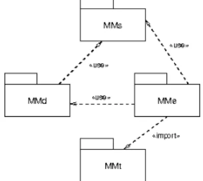
So, when defining an executable DSL for dynamic systems, several aspects have to be dealt with. They can be captured in the following metamodels (whose relationships are shown on figure 5):
• The static (or structural) metamodel MMs is the classical modelling language metamodel. It is required for any language in Topcased.
• The dynamic metamodel MMd extends MMs with the attributes, relations and elements required in order to execute a model.
• The event metamodel MMe defines on one hand the events that drive the execution of the model and on the other hand the events which are produced by the execution of the model, that is exogenous and endogenous events.
• The trace metamodel MMt records all external and internal events that occur during the execution of the model. A trace that only contains external events defines a scenario. The metamodel of a DSL, that is its abstract syntax, may be formalised as the following tuple:
MM = < MMs, MMd, MMe, MMt >.
In the previous definition, we have not yet expressed the semantics itself, that is the way the model evolves according to the input events in the scenario. It will be presented in the next sections as part of the simulation engine.
Figure 5: Metamodels dependencies 5.2 Model animator
The animator allows the user to control the animation through a player-like control panel. The main part of the window shows the model being animated. As the designer has defined his model using the Topcased editor, it may be intuitive to reuse the graphical representation of the model provided by the editor to show the current state of the model during animation. Dynamic properties are thus displayed on the graphical representation of the model. For example, current states are displayed as red rectangles the firable transitions as green edges. This is achieved thanks to simulation components that spy the changes of dynamic properties defined in the dynamic metamodel and update accordingly the graphical view of the model. The main benefit of this approach is that no modification is required on the editor configurators that were defined during the construction of the graphical editors. Animation is only built atop the editor and takes advantage of the
ability to change graphical properties of the editor widgets and to extend them with decorations.
The animated model may also be inspected in detail by using the properties view of the Eclipse platform that is automatically activated when the Topcased perspective is selected.
Other visualization tools may be started from the animator but they are not yet implemented.
5.3 Scenario builder
The event metamodel defines the types of event that may occur during a simulation. It is specific to a given DSL. For example, for state machines, one external event consists in injecting a new signal into the state machine.
A graphical event editor may be useful to trigger events while animation is running. One possibility is to replace or complete the editing palette of the editor by an event builder palette that allows to inject new events to the execution.
The ability to define a specific graphical user interface to generate events is certainly a strong point as discussed in section 3.3. A metamodel of the graphical components and a link to the triggered event could be defined in the same way the Topcased editor generator is done. It has not been implemented yet and should be specifically designed for any new DSL.
The event or scenario builder aims to inject events that will drive the simulation. An interactive event generator is defined on the main window of the animator. When the user clicks on the play button, he is asked for the UML2 signals to inject in the state machine. The user can save the scenario of all the events he has interactively injected.
When the animator is started, the user may decide to load a predefined scenario, for example the one saved during a previous execution or defined thanks to a scenario generator.
5.4 Simulation engine
The simulation engine is in charge of updating the dynamic properties of the animated model according to one event occurrence. It consists of two main components. The first one is a generic discrete event based engine that manages an agenda of all the identified events ordered according to their occurrence time. It only relies on the trace metamodel and thus does not require to be changed to handle a new DSL. The second component is specific to the considered DSL. It provides the execution semantics of the DSL. More precisely, it defines how the model, in fact dynamic properties, should be updated according to one event occurrence. For our current state machines, only two external events have to be dealt with. The first one is “inject a signal”. It consists in adding the
corresponding signal to the list of signals received by the state machine. The second one is “run”. It asks the state machine to treat the received signals and thus to evaluate firable transitions and change current states according to the fired transitions. The Topcased toolkit relies on the Eclipse environment. As Eclipse is implemented using the Java language, Java is the most appropriate solution for development. EMF provides the required libraries to read, create and modify models conforming to Ecore. EMF also provides a code generator (based on JET templates) that produces Java classes respecting the Ecore definition of the meta-model. We have decided to define an ad-hoc simulation engine. It consists in an Eclipse plugin for the generic discrete event agenda. A Java interface defines a method for each exogenous event defined in the event metamodel of the DSL. This design decision allows to easily define several semantics for a given DSL by defining a new implementation of this interface. Furthermore, it may be used as a way to take into account semantic variation point that are generally part of the definition of modelling languages like UML.
This approach is the most efficient one in term of memory footprint, running time and initial development time. However, it produces code that is very hard to reuse for executing another kind of model. The modelling language semantics is defined in a very pragmatic way closely tied to the syntax and it is very hard to extract a formal representation suitable to formal proof of correctness for the tools. Other approaches have been identified in [5] that will be further investigated.
5.5 Tools interactions
The different models (static, event, trace and dynamic models) are represented using EMF (Eclipse Modelling Framework) [3], and stored, either in memory as Java objects instances of the classes generated by EMF (or created by the dynamic reflexive API), or serialized as XMI or XML files. Topcased relies on a model bus in order to facilitate the relation between components. The available bus requires the use of the serialisation approach. However, this approach is quite costly. So, communication between the animator, the event builder and the execution engine is achieved through the shared in-memory EMF-representation of the model and relies on EMF-generated observers to keep a low coupling between those different tools. 5.6 Current prototype
A prototype of the UML2 StateMachines simulator has been developed. A screenshot of the simulator running the flashing lights is shown on Figure 6. It reuses the visualization of the model created while building the model with the Topcased graphical
editor. During simulation, it is possible to inspect the dynamic information of the model thanks to the dynamic simulation view. It is especially useful for the properties that are not graphically presented. A control view allows to control a simulation with a start button, a stop button and a step by step button. At the moment, the simulation is either interactive or driven by a scenario chosen and loaded when the simulator is started. A batch mode is also possible. This mode is useful for scenario driven simulation as it automatically makes the model evolve according to the scenario with a short delay between steps so that the user can see what happens.
Figure 6. Snapshot of the current prototype.
6. Conclusion and Perspectives
Model Driven Engineering is becoming a tool of choice for the design of critical embedded systems as it allows to integrate smoothly several modelling languages, thus providing a better way to manage the numerous concerns involved in such systems. The Topcased toolkit aims at providing a framework integrating existing tools for easily defining new Domain Specific Modelling Languages (DSML) for safety critical embedded systems. One key point is the validation and verification of the produced systems. For this purpose, simulation and model animation allows the user to validate his requirements and the designer to verify that his model satisfies these requirements. It is therefore of uttermost importance to ease the integration of simulators and model animators in the toolkit. This contribution presents the preliminary results of the integration of these kinds of tools for the UML2 StateMachines in Topcased. We have presented discrete event simulation used for developing critical embedded systems, the proposed simulation archi-tecture, and insights on how it could be integrated in a MDE way. The simulation architecture involves scenarios generation or interactive construction,
model execution, and simulation result exploitation (either in or off line). This lead to the development of the first version of the tools that will be integrated in the next Topcased release synchronised with Eclipse Ganymede in July 2008.
The next step in the simulation of UML2 State Machines will be to handle classes and their instances. An instance will then run the state machine of its class. In the flashing lights example, the left and the right lights are both instances of the same FlashingLight class. We will then be able to handle states of instances that will be updated according to the corresponding UML2 actions (used in the activities associated to transitions). The state of instances will also be used in transition guards.
The process proposed in this paper to add simulation to a DSML is currently used to provide animation capabilities for the SAM language (a component and automata based language) and an executable extension of the SPEM process description language defined by the OMG. These experiments should point out generic components (like the discrete event simulation engine or the trace metamodel). We will also provide tools to automate the generation of simulators as it is already done for the construction of graphical editors thus allowing a model driven engineering approach to the integration of simulators.
7. References
[1] Topcased project, 2007 http://www.topcased.org/
[2] Eclipse website, 2007. http://www.eclipse.org/.
[3] EMFT (Eclipse Modeling Framework Technology)
project, 2007. http://www.eclipse.org/modeling/emft/.
[4] GMT (Generative Modeling Technologies) project,
2007. http://www.eclipse.org/gmt/.
[5] CNRS-IRIT and ONERA-CERT. Synthesis on
Simulation Needs. Technical report D01 , WP2,
Topcased project, 2006.
[6] CNRS-IRIT and ONERA-CERT. Synthesis on Methods
and Tools for Simulation. Technical report D02, WP2,
Topcased project, WP2, 2006.
[7] B. Ziegler, H. Prahofer, and T. Kim. Theory of Modeling
and Simulation: Integrating Discrete Event and Continuous Complex Dynamic Systems. 2nd Edition,
Academic Press, 2000.
[8] Ptolemy II Heterogeneous Modelling and Design, 2007.
/http://ptolemy.berkeley.edu/ptolemyII/.
[9] Object Management Group, Inc. Unified Modeling
Lan-guage (UML) 2.1.1 Superstructure Specification, Feb.
2007. http://www.omg.org/docs/formal/07-02-05.pdf.
[10] Eclipse UML2 plugin website, march 2007.