Character Segmentation Heuristics for Check Amount Verification
by
Salman Amin Khan
Submitted to the Department of Electrical Engineering and Computer Science in Partial Fulfillment of the Requirements for the Degree of Master of Engineering in Electrical Engineering and Computer Science
at the Massachusetts Institute of Technology June 1998
Copyright 1998 Salman Khan. All rights reserved.
The author hereby grants to M.I.T. permission to reproduce and distribute publicly paper and elec-tronic copies of this document in whole or in part, and to grant others the right to do so.
A uthor ... ...
Department of Electrical Engineering and Computer Science May 26, 1998
Certified by ... ... . .. Dr. Amar Gupta Thesis Supervisor
A ccepted by ... ... ...
M USSACHuEnTS INSTITUTE Arthur C. Smith
OF: TECHN OGY Chairman, Department Committee on Graduate Thesis
Character Segmentation Heuristics for Check Amount Verification
by
Salman Amin Khan
Submitted to the Department of Electrical Engineering and Computer Science May 26, 1998
in Partial Fulfillment of the Requirements for the
Degree of Master of Engineering in Electrical Engineering and Computer Science at the Massachusetts Institute of Technology
ABSTRACT
Automatic check amount verification involves three basic steps: 1) finding the courtesy amount (the numerical amount) on the check, 2) segmenting that amount into its individual characters, and 3)Using a recognition engine to recognize the individual characters and, thus, recognizing the check's amount. This thesis will focus on improving the segmentation process. In particular, it will focus on the classical approach of segmentation based on charcter features alone (i.e. not aided by recognition). A segmentation workbench is developed for the purpose of studying cur-rent and potential techniques for numerical digit segmentation. The problem of segmenting over-lapping or touching characters is studied in detail. Also, a hybrid heuristic involving a
combination and variations of the "drop-falling" algorithm is developed which has promising results. This algorithm is then incorporated into a complete optical character recognition system. Thesis Supervisor: Amar Gupta
Title: Co-Director, Productivity from Information Technology (PROFIT) Initiative, Sloan School of Management
Acknowledgments
I would like to thank Dr. Amar Gupta for the time that he put in helping me flesh out the research done in this thesis.
I would like to thank my mother, Gulnar Khan, and my sister, Farah Khan, for all the help and support they have given me throughout my life.
Table of Contents
Chapter 1:Introduction 6
1.1 Overview of handwriting recognition 6
1.2 The problem of automatic check amount verification 7
1.3 Segmentation Overview 8
Chapter 2: Fundamental Segmentaion Issues 10
2.1 Thresholding of the numeral image 10
2.2 Extracting connected components 11
2.3 Classification of connected components 12
Chapter 3: Current Segmentation Techniques 14
3.1 Hit and Deflect algorithms 15
3.2 Drop Fall algorithms 15
3.3 Structural feature-based segmentation 17
3.4 Min-Max algorithms 18
3.5 The need for developing more sophisticated segmentation methods 19
Chapter 4: The Hybrid Drop Falling Technique 21
4.1 The traditional "drop-falling" heuristic 21
4.2 Variations of "drop-falling" 24
4.3 Evaluation of the variations of drop falling 26
4.4 Hybrid drop fall heuristic 29
Chapter 5: Development and Design of the Segmentation Tool Box 32
5.1 Functionality of the segmentation tool box 32
5.2 Structure and implementation of the graphical user interface 34
5.3 Image formats and representations 35
5.4 Implementation of connected component finder 36
5.5 Heuristic for recognizing and connecting disjointed fives 38 5.6 Heuristics for recognizing touching or overlapping characters 41
5.7 Techniques for splitting connected characters 42
Chapter 6: Implemenation of Hybrid Algorithm within WinBank 45
6.1 The min-max based algorithm 45
6.2 The hit and deflect algorithm 46
6.3 Implementation of the hybrid drop fall algorithm 46
Chapter 7: Performance Results 48
7.1 Overall performance 48
7.2 Effectiveness of disjointed five heuristic on extreme cases 48 7.3 Recognition of connected characters with heavily skewed aspect ratios 51
Chapter 8: Conclusions
Chapter:9 References 59
Appendix 60
A. 1 Code for Segmentor's graphical user interface 60
A.2 Connected Component Finder Routine 65
A.3 Breadth first search routine used in Segmentor 66
A.4 Classifier Routine 68
A.5 Connected Component Splitting Routine 68
A.6 Drop Fall Routine 69
Chapter 1:Introduction
People have always tried to develop machines which could do the work of a human being. The reason is obvious since for most of history, man has been very successful in using the machines developed to reduce the amount of physical labor needed to do many tasks. With the advent of the computer, it became a possibility that machines could also reduce the amount of mental labor needed for many tasks. Over the past fifty or so years, with the development of com-puters ranging from ones capable of becoming the world chess champion to ones capable of understanding speech, it has come to seem as though there is no human mental faculty which is beyond the ability of machines.
There is one human ability, however, which has eluded the prowess of machines.--namely, that of recognizing a human's handwriting. Of course, much progress has been made in the way of computer handwriting recognition, but few of us believe that a computer will ever be able to read a human's handwriting as good as a human. Even so, it doesn't hurt to try to develop tech-nology which can approach the recognition ability of humans. After all, even less-than-perfect handwriting recognition has its uses.
1.1 Overview of handwriting recognition
Handwriting recognition is an extremely large field which can be divided into two general sub-fields: on-line and off-line recognition. On-line recognition is the process of recognizing the characters as they are being written. Examples of systems that employ on-line recognition
include the Apple Newton and the Palm Pilot. On the other hand, off-line recognition is recogniz-ing the characters after they have been written. Off-line recognition systems' potential uses lie in fields such as document processing, mail direction, and check verification. Due to the lack of
stroke and timing information, off-line recognition is considered a much harder problem than on-line recognition.
1.2 The problem of automatic check amount verification
One particular important application of off-line handwriting recognition is check amount recognition. This subfield is very important because of its potential for reducing the overhead in processing checks. 66 billion checks are written annually in the United States alone and it is believed that this number will continue to grow well into the next century [12]. The amounts writ-ten on each of these 66 billion checks has to be encoded (ofwrit-ten several times) by hand, resulting in a non-trivial expense on the part of banks and the Federal government. Drastically reducing the number of checks which have to be read by hand using automated handwriting recognition could potentially save billions of dollars in the United States alone.
Many systems are already in existence which attempt to tackle the problem of check amount recognition, but none are perfect. Depending on whom you ask, the best check amount recognition engines today have about 50%-85% recognition rates [1, 3, 11]. This means that these systems can provide, with a reasonable level of confidence, the numerical amounts written on 50%-70% of all checks written. Even more, of the 50%-70% of the checks which are recog-nized, a certain portion are recognized incorrectly (currently .1% for the best systems). Even though an error rate as small as one in a thousand checks may seem minor, it could be very signif-icant in the real world if, for example, a $1,000.00 check is misread to be $100,000!
Any system which attempts to recognize the amount written on a check will have to tackle three fundamental problems (which will be described in further detail later on): (1) finding the courtesy amount block (CAB) on the check; (2) segmenting the digits, commas, and decimals in the CAB; and (3) preprocessing and recognition of the individual characters in the CAB. The first
issue has been addressed in other research [2] and, thus, will not be dealt with in this thesis. The segmentation and recognition steps are what this thesis will focus on.
1.3 Segmentation Overview
This thesis will focus on the problem of segmentation in particular. Segmentation, or separating out the individual characters which constitute a written character string, is a straightforward pro-cess when the characters are well-spaced and written with some degree of neatness (Figure 1). In that ideal situation, one just has to pick out each connected component. The problem becomes much more difficult (Figure 2) when characters are touching, overlap, or disjointed.
Figurel: Example of well written numerical amount
Figure 2: Examples of a) touching b) disjointed and c) overlapping numbers
There are several steps commonly employed today for segmenting an image of a numeri-cal string. The first step in segmenting any string of symbols is to identify the connected
compo-nents in the image of the string. Connected pixels are usually grouped together using some sort of a search algorithm (which will be described in Chapter 5). Once the connected components are found, they then have to be classified according to whether they represent part of a character, a whole character, or two or more characters. This is commonly done using a variety of heuristics
which make use of the components' aspect ratios and positions. If a connected component is clas-sified as being made up of more that one character, then another 'splitting' heuristic is used. For example, a common algorithm used today is the min-max algorithm which separates the con-nected characters by splitting the concon-nected region from a minimum on the upper contour to a maximum on the lower contour (Figure 3). Similar splitting heuristics have also been employed by Dimauro et al.[l].
The heuristics tend to be effective in general, but still fail on a significant portion of cases with many connected or overlapping digits. In fact, the inability of current systems to properly segment these character strings has been the limiting factor in building better recognizers. Since the recognition process is doomed to fail without correct segmentation, it is vitally important for the segmentation process to become more robust if automatic check verification is ever to be com-mercially feasible. The research described in this thesis attempts to extend the heuristic set in order to enhance segmentation performance.
In order to facilitate the heuristic experimentation, a graphical workbench called the Seg-mentor was developed. This tool enables the user to quickly change test data and modify heuris-tics. This tool is used extensively in experimenting with the variations of 'drop-falling' type algorithms.
Chapter 2: Fundamental Segmentaion Issues
Segmentation is the process of separating out the individual digits which make up a num-ber. Although it is a straightforward task when dealing with typewritten or well written numbers, it can be quite difficult when the digits are handwritten. The main reason for this is that handwrit-ten characters ofhandwrit-ten overlap and, in some cases, may be disjointed. Also, the wide variations in
handwriting styles make it very difficult to make generalizations for making segmentation heuris-tics. In this chapter, we will explore the basic processes common to any system dedicated to handwritten numeral segmentation and the assumptions on which they are based.
2.1 Thresholding of the numeral image
Before any segmentation or processing on a numerical image can be done, it is very useful to convert the image from grayscale or color to a black and white bitmap. This is a very simple process which entails just scanning the image and changing each pixel value to either black or white depending on whether they are above or below a given threshold. The threshold chosen should be a function of the intensity range of the pixels in the image.
The threshold-determining function can be made arbitrarily complex to optimize the conver-sion process, but setting the threshold to the average of the minimum and maximum threshold val-ues is usually sufficient. This heuristic will break down only when the average of the minimum and maximum pixel values is either less than many of the pixels meant to represent black or greater than many of the pixels meant to represent white. This could happen if, say, most of the pixels values fall in the 150-255 range, but there is one pixel with a value of zero. Since this is
unlikely to happen (devices that scan the images are very unlikely to produce images with random pixel values so far from the range of most of the other pixels), it is usually not necessary to worry
about these special cases. Alternate heuristics which could take care of the above-mentioned problem (but have their own cases on which they fail) include basing the threshold on the
weighted average of all the pixels or determining white or black pixels based on changes in con-trast (for example, if two adjacent pixel values differ from each other significantly, than set the lighter one to white and the darker one to black.
2.2 Extracting connected components
The first step in actually segmenting any numeral image is to extract out each of the con-nected components. In order to do so, it is necessary to find a black pixel and to then use a search algorithm to find all of the pixels which are connected to it. Once all of those pixels are recog-nized, they should be grouped together into one connected component. Then another, as yet not-looked-at, pixel needs to be found on which the process of searching for all of the connected com-ponents is repeated. The overall process is repeated again and again until every black pixel in the image is classified as being part of a connected component.
We say that two pixels are connected to each other if they are adjacent. Since the charac-ters which are being segmented are at least several pixels wide, it is unusual for two pixels which are only diagonal with respect to each other (they share no other adjacent neighbors) to be part of the same character. This is why, in searching for connected pixels to a given pixel, it only neces-sary to take into consideration the pixels above, below, to the right, and to the left of that pixel.
If the digits in the numeral image are well separated when they are written, then each con-nected component would represent a whole character in the numeral string and the task of seg-mentation would be done. Unfortunately, this is seldom the case. If any of the digits are
more than one character, or part of a character. How we classify the connected components into one of these three categories is the subject of the next section.
2.3 Classification of connected components
Most segmentation methods today classify the connected components using information on their sizes and positions. The ratio of a connected component's bounding box height to its width is the most common indicator of what fraction of characters the component is composed of. If the width is greater than a certain multiple of the height, then it is very unlikely that the compo-nent is only one character. More likely, it is either more than one character or part of a character that is a horizontal line.
Although using the width-to-height ratio is useful for the more standard cases, it is not dif-ficult to find cases on which it breaks down. For example, very often the numbers 2,3,5,or7 are written so that they are unusually wide. Moreover, a 1 and 7 could be connected together and the resulting connected components would have a height to width ratio identical to the 7 alone. Because of this, it is a nontrivial problem to robustly determine how many characters a connected component is composed of.
Using a connected component's width-to-height ratio and position is much more useful in identifying whether or not the component is a separated segment of a larger character. The most common case of this happening is when the top stroke of a five is separated from the rest of it. In this case the top stroke, which is an almost completely horizontal line, would have a very high width to height ratio (much higher than even a connected component composed of many charac-ters). Not only that, but the height of the component will be significantly less than the heights of
the other connected components in the image and its bounding box will be contained in the upper half of the image. Based on these assumptions, it is not difficult to find the upper stroke of a five
(the only characters that it could conceivably be confused with are the commas and decimal points, but those are located in the lower half of the image and would not have as high of a width
to height ratio--this is described in more detail in Chapter 5).
As we can see, robustly classifying the components is not an easy thing to do. More com-plicated heuristics based on features other than the aspect ratios and positioning of the compo-nents will have to be developed in order to more accurately classify them. These heuristics could potentially make use of min-max points on the upper and lower contours and come type of com-plexity measure of the pixels making up the component, in conjunction with the aspect ratio and positioning, to make a better guess at properly classifying the component.
Chapter3: Current Segmentation Techniques
Many different methods have been developed over the past 50 years for the purpose of separating two connected characters [1, 3, 4, 5, 6, 7, 8]. Despite the wide variety in the methods developed, they can be divided into two groups: 1) those that are based only on character features and b) those that make use of some type of pre-recognition process. Since the focus of this thesis is on developing a heuristic which falls under the first of the two categories, we will restrict our-selves to surveying feature based techniques only in this chapter.
Once a connected component is classified as being composed of more than one character, all that is left to be done is to determine how many characters the component is composed of and how to optimally separate the characters. Most of these components will be composed of two characters, but in unusual cases they can be composed of three or more. Heuristics similar to the ones employed in Section 2.3 can be used to determine just how many characters make up the component. As mentioned in that section, these heuristics are not perfect and can lead to
misclas-sification in special cases. To simply the discussion, we will focus on the case where there are two connected characters involved and then extend the heuristics developed for that problem to the case of three or more characters.
The algorithms to be discussed in this chapter can be classified under the categories of "Min-Max", "Hit and Deflect", "Drop Fall", and "Structural Feature" based segmentation. Col-lectively, they constitute the major types of nonrecognition-based segmentation algorithms being used today. Drop fall based algorithms will be studied in further detail in Chapter 4 as they pro-vide the basis for the hybrid drop fall algorithm developed as part of this thesis.
3.1 Hit and Deflect algorithms
Hit and Deflect algorithms attempt to find an optimal path for cutting a connected compo-nent by literally hitting and deflecting their way through the connected compocompo-nent. Casey et al.
[6] define Hit and Deflect algorithms to be those "able to compute a curved segmentation path by iteratively moving a fixed point." Most implementations of this type of algorithm involve a set of rules which dictate in which direction to continue construction of the cutting path based on the surroundings of the current path pixel. The rules could be designed so as to mimic other segmen-tation heuristics such as min-max or drop fall (to be described in the next section) methods.
One of the earliest examples of employing a hit and deflect strategy into a segmentation system was done by Shridar and Badredlin [7] in 1986. They used Hit and Deflect in an attempt to segment handwritten words. Their system first tried to separate out characters by a performing a vertical scan near the middle of an image. If the scan resulted in zero or two black-to-white or white-to-black transitions, then it was assumed that the characters were either not connected or simply connected (connected at only one point). In this case, the scan line would provide a suit-able segmentation path. On the other hand, if scan line crossed more than two transitions, the assumption was made that the characters are slanted. This is when a Hit and Deflect-type algo-rithm was used. Their algoalgo-rithm starts from a peak in the lower contour of a connected compo-nent. It then attempts to move upwards according to a series of rules. These rules are designed to minimize the number of cuts which have to be made though the component. The algorithm would finish once it reaches the top of the image.
3.2 Drop Fall algorithms
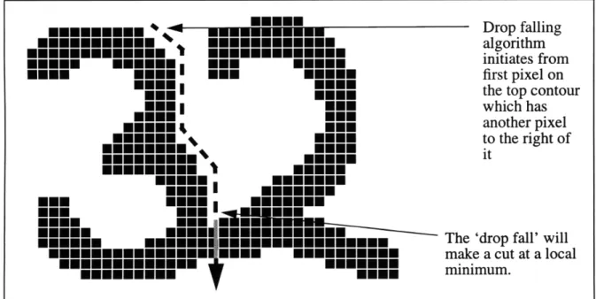
Drop fall algorithms attempt to build a segmentation path by mimicking an object falling or rolling in between the two characters which make up a connected component (Figure 3). This
class of algorithm was first proposed by Congedo et al. in [10]. There are four primary types of drop-fall algorithms which differ on the direction and the starting point of the drop fall. These are top-left (or left-descending), top-right (or right-descending), bottom-left (or left ascending), and bottom-right (or right ascending). Although similar in techniques, each of these variations has their own strong and weak point which will be explored further in Chapter 4. Since the imple-mentation of a drop fall algorithm usually involves a set of rules which dictate the next pixel in the path of the fall which are based on the current position, drop fall algorithms could be seen as a specific type of Hit and Deflect algorithm. In the next chapters, we will explore how combining variations of the drop fall algorithm could lead to a potentially more powerful segmentation tech-nique.
nIInNEM
Drop falling3mmmmmmmmmmm Eme.Mepf algorithm
m
mm
mmmmmm
mmm
mmmm
initiates fromMEM NONE NNE MEEM first pixel on
Emmm NONE the top contour
EmmI ONE which has
MM mmm another pixel
m*mmmm mE to the right of
mnmmmm. NONE it
MEN mm I mEMMM
mmm.
mm
MNM mmmmm mmmmmmmmmm The 'drop fall' will
mEmEmEmE mm mmEMmm mEmmEmmEmE make a cut at a local
EmEmmmEmEE mmmm minimum.
3.3 Structural feature-based segmentation
Another major type of nonrecognition based segmentation heuristic involves basing the segmentation of a connected component on structural features in the component itself. These could be points at which the slope of the contour changes dramatically or extrema within the com-ponent. Examples of systems which use structural feature-based segmentation are given in [8] and [9].
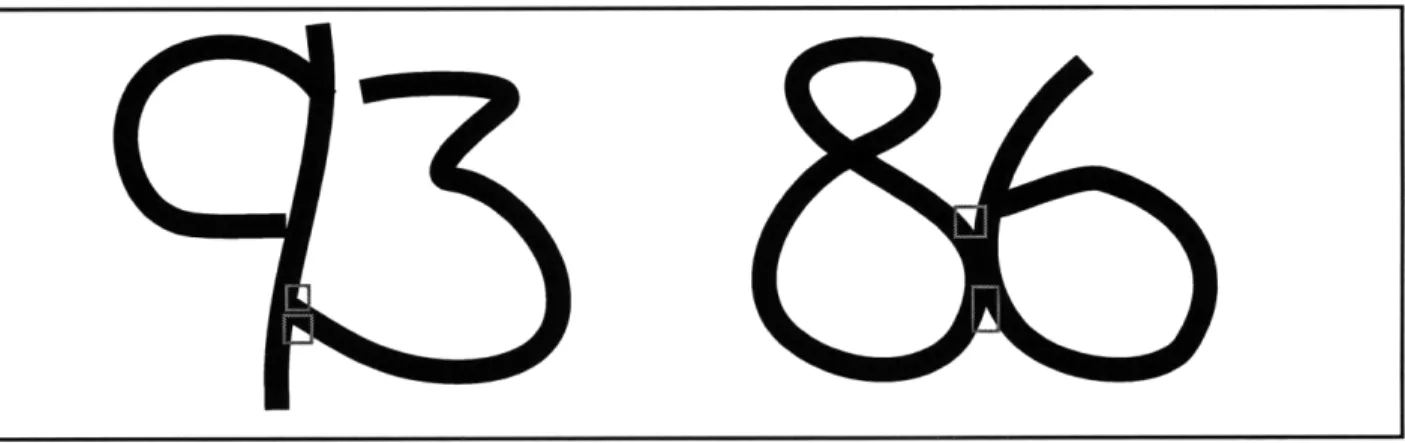
Figure 4: Structural features which could be entry or exit points of intersecting strokes
The segmentation method developed by Strathy et al. in [9] is a prime example of a rela-tively successful feature-based algorithm. This method attempts to identify structural features which could signify entry or exit points of overlapped or touching strokes (Figure 4). It takes into consideration the fact that the strokes could be straight or overlapped. The routine starts off by identifying significant contour points (SCP) which are either: 1) corner points, 2) local minima, 3) local maxima, or 4) a potential exit point of a straight stroke created by extending a contour through a concave corner (Figure 5). From this pool of SCPs, the algorithm selects a pair of points which could be the entry and exit points for the best cutting path. The points are chosen based on features such as:
* whether one is a minima and the other is a maxima * corner points are preferred
* the closer the points are to each other the better * the sharpness of the concativity at the SCPs
* the degree to which a minima is directly above a maxima
* the distance of a minima/maxima to the next local maxima/minima * preference for pairs closer to the left side of the image
This method was tested on a small set of USPS zip codes and resulted in accuracies rang-ing from 48 to 97% [9]. Although these numbers are encouragrang-ing, one has to keep in mind that segmenting zip codes is an easier problem then check amounts since zip codes have a constant number of characters and are usually better spaced than check amounts.
Figure 5: Significant contour points (SCPs)
3.4 Min-Max algorithms
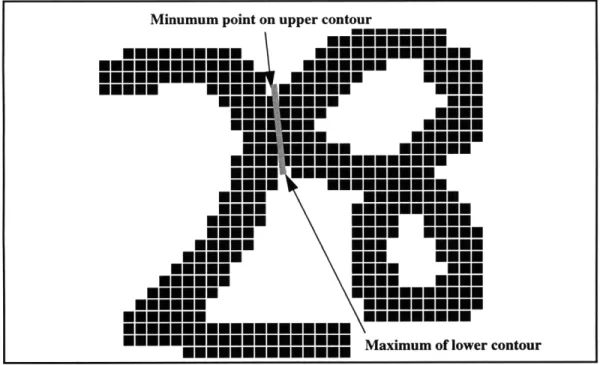
Min-max algorithms are some of the most common employed in segmentation systems today [1, 5] and can be considered a subclass of structural feature-based methods. They are bases on the premise that most touching or overlapped characters are joined where the distance from the upper contour to the lower contour of the connected component is a minimum. The algorithm
finds this minimum by examining the extrema on the upper and lower contours. In particular, it identifies the minima in the upper contour and the maxima in the lower contour. Then, a straight-line path is picked between an upper-contour minima and a lower contour maxima. The decision
as to which minima and maxima to connect is usually based on values such as the distance of the cut from the center of the image, the distance between the extrema, and the number of white-black
or black-white transitions encountered along the cut.
Figure 6: Example of a cut produced by a min-max based heuristic
3.5 The need for developing more sophisticated segmentation methods
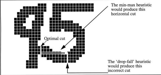
The heuristics described in this chapter work reasonably well for a large number of cases, but they also fail badly for a lot of other cases (Figure 7). Also, the 'global' approaches such as
structural feature-based segmentation tend to be extremely computationally expensive as opposed to the more local "Hit and Deflect" and drop fall approaches. Because of this, it is useful to explore ways of modifying and combining these heuristics so as to produce better results more
often. It is this search for a more optimal combination of these heuristics which is one of the cen-tral points of this thesis. The hybrid algorithm developed is the subject of the next chapter.
MEN EmEEEEE EEE The min-max heuristic
mimmmE
nnmmnmnm
would produce thismNmmmN ON horizontal cut
OEN EN. EE EE
MEu. Eu.. EEMEE.E
NES. EuN.EE EEEMEE
EM M 0ptimal cut
ONuE MEE ..
mmmmm Nmum
Emmm. EUHUEH IEEE
mM'iM -4MEMIE MNim
EEM mEmE E The 'drop-fall' heuristic
MOEN would produce this incorrect cut
Chapter 4: The Hybrid Drop Falling Technique
Drop falling algorithms are based on the principle that a fairly optimal 'cut' between two connected characters can be made if one were to role a hypothetical marble off the top of the first character and make the cut where the marble falls. Despite its apparent simplicity, the algorithm has proven itself to be quite useful. In this chapter, the basic steps involved in drop-falling will be explored. We will also take a look at a new heuristic based on the drop-falling principle which is more effective.
4.1 The traditional "drop-falling" heuristic
As mentioned above, the drop-falling heuristic is based on the principle of letting a hypo-thetical marble fall in between two connected characters and making the cut where the marble lands. Based on this simple description of the method, the main issue which needs to be
addressed in its implementation is where to drop the marble from. This is important since if the algorithm starts in the wrong place, the 'marble' could easily roll down the left side of the first digit or the right side of the second digit and, thus, would be completely ineffective (Figure 8).
There are several methods available to decide where to start the drop-falling process from. Obviously, it is best to start as close as possible to the point at which the two characters are con-nected. Dimauro et al [1] outline a method which does this quite robustly. In this method, the pixels are scanned row-by-row until a black boundary pixel with another black boundary pixel to the right of it is detected, where the two pixels are separated by only white space. This pixel is then used as the point from which to start the drop-fall (Figure 9).
Initiating the drop-fall here causes the algorithm to proceed to the left of the first character
Initiating the drop fall here causes the algorithm to proceed to the right of the second character
Figure 8: Examples of bad initial points from which to start the drop-fall
By scanning row-by-row, left to right, this is the first pixel which would meet the criterion of being a border pixel separated from another pixel to the right only by white space.
Figure 9: Pixel from which to commence the drop-fall
A more naive choice for the initial pixel would be the first pixel found by scanning row-by-row which has white space to the right of it. This method fails, however, in when the first such
pixel encountered is part of the second of the two connected characters. In this case, the algo-rithm will 'fall off' the right side of the characters as depicted in Figure 8.
After the initial pixel is found, the next step is to begin the actual drop fall. The drop-fall-ing algorithm is designed to mimic falldrop-fall-ing, so it will always move downwards, diagonally down-wards, to the right, or two the left. The directions that the algorithm will 'move' in according to
the current pixel position and its surroundings are outlined in Figure 10.
Initial Position Direction of Direction of
Initial Position movement' Initial Position 'movement'
mmoENm7
mm-m
[]White Pixel Black Pixel
I
Current Pixel ew Pixelm
Any PixelFigure 10: Pixel-to-pixel path construction based on current position
As we can see from Figure 10, the algorithm mimics a falling motion. When obstructed by a black pixel directly below it, the algorithm attempts to move to the right and then to the left. In the case when the current pixel is completely obstructed by black pixels, the algorithm bores
directly down through the pixels. The algorithm continues to move from pixel to pixel in this fashion until the bottom of the image is reached.
4.2 Variations of "drop-falling"
The standard version of the drop-fall algorithm described above falls down and to the right from the top left of the connected component. There are three other variations of the algorithm accept for the fact that they don't necessarily initiate from the top left or fall 'down'. The differ-ences will be made more clear as we look at the three other variations.
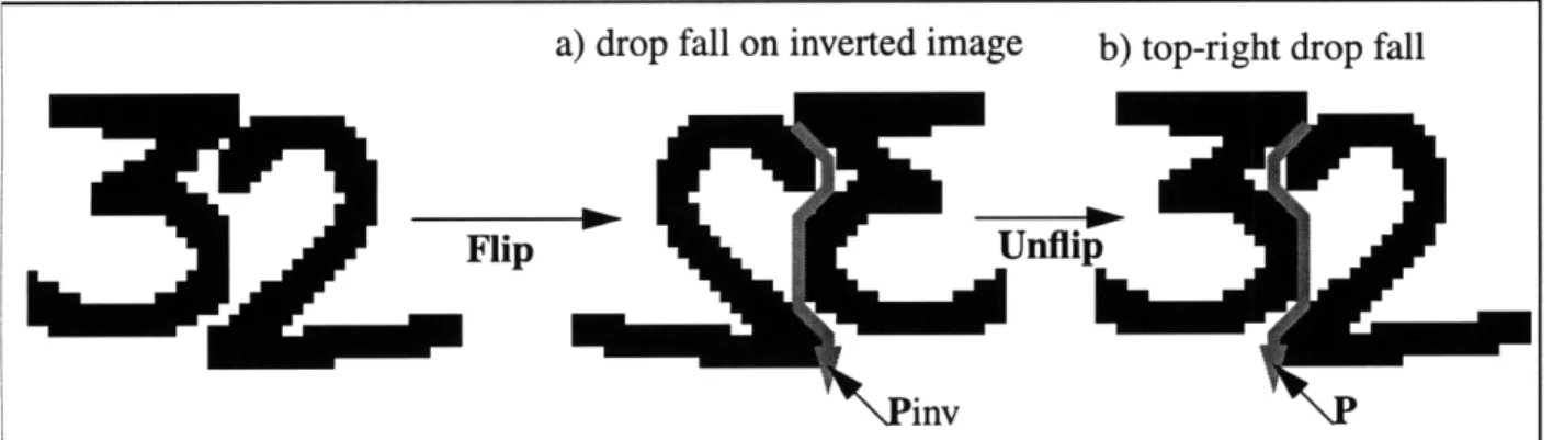
* Top-Right Drop Fall: This algorithm is identical to the standard drop-fall accept that it
ini-tiates from the top-right of the connected component rather than the top left. Also, instead of falling down and to the right, it falls down and to the left (Figure 1 lb). The standard drop fall algorithm can be used if the input image is 'flipped' vertically (Figure 1 la). The resulting
seg-a) drop fall on inverted image b) top-right drop fall
Flip Unflip
inv
Figure 1l:Implementation of (b)top-right drop fall by applying (a) standard drop fall to an inverted image
mentation path P can be obtained through the transformation of equation (1) where Pinvx is a
vector of the x coordinates (or column indices) of the segmentation path resulting from the standard drop fall algorithm being performed on the vertically inverted image; Pinvy is the vector of the y coordinates (or row indices) of the segmentation path resulting from the
stan-dard drop fall algorithm being performed on the vertically inverted images; and w is the width of the image.
Pxi = w -Pinvxi
for i=1, 2, ..., n where n is the length of Pinv (1) Pyi = Pinvy,
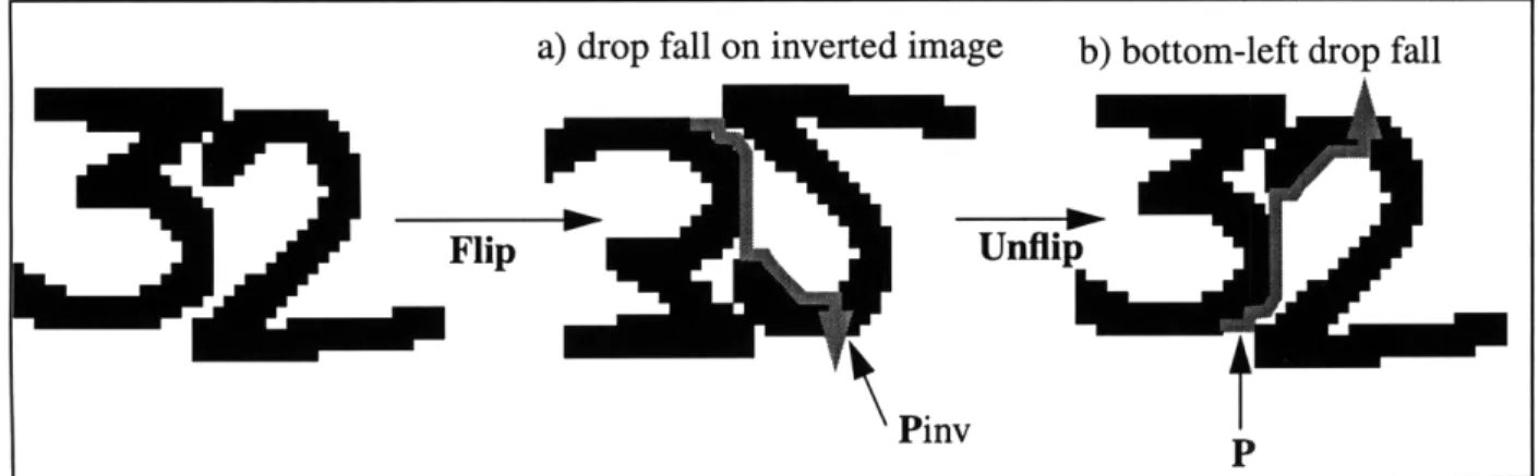
* Bottom-Left Drop Fall: This algorithm is identical in principle to the original drop-fall algo-rithm accept that it initiates from a pixel at the bottom left of the image and 'falls' up and to the right (Figure 12b). This algorithm can be implemented by performing a standard drop-fall on an input image which is flipped along its horizontal axis (Figure 12a). The bottom-left drop fall path can then be obtained using equation (2) where h is the height of the image.
a) drop fall on inverted image b) bottom-left drop fall
Flip Unflip
Pinv
t
Figure 12:Implementation of (b)bottom-left drop fall by applying (a) standard drop fall to an inverted image
Px = Pinvx'
for i= 1, 2, ..., n where n is the length of Pinv (2) P = h - Pinvyi
* Bottom-Right Drop Fall: This splitting heuristic is identical to the pervious three accept that in this case, the falling commences from the bottom right of the image and goes in an up and leftward direction. It can be viewed as the exact opposite of the standard top-left drop fall. As
before, a bottom-right drop fall (Figure 13b) can be implemented by performing a standard
Figurel3:Implementation of (b)bottom-right drop fall by applying (a)standard drop fall to an inverted image
top-left drop fall after appropriately transforming the input image (Figure 13a). This time, the image must be flipped in both the horizontal and vertical directions. The bottom-right path P can be obtained from the transformation of Pinv given in equation (3).
Px, = w - Pinvxi
for i=1, 2, ..., n where n is the length of Pinv (3)
Py= h - Pinvy i
4.3 Evaluation of the variations of drop falling
Despite the apparent similarity between the variations of the drop-fall heuristics outlined above, they do very often provide very different segmentation paths for various test examples. For any of the drop-fall heuristics, it is easy to find cases where they work well and where they
don't work well. It is however, much more difficult to find examples when all of them do not work well. In the next section, this principle will provide the basis for the construction of a hybrid
heuristic which makes use of all of the aforementioned drop-fall variations. Now, we will look at the kinds of examples where each of the drop-falls tend to succeed or fail.
Figure 14: Examples for which the top-left drop fall heuristic succeeds
First, we will focus on the standard top-left drop fall. At first glance, this seems to be a very robust method for segmenting two connected characters (Figure 14). However, one does not have to look too long to find test examples where it fails rather miserably (Figure 4). Figure 15 shows
several more examples of when the top-left drop fall heuristic will fail.
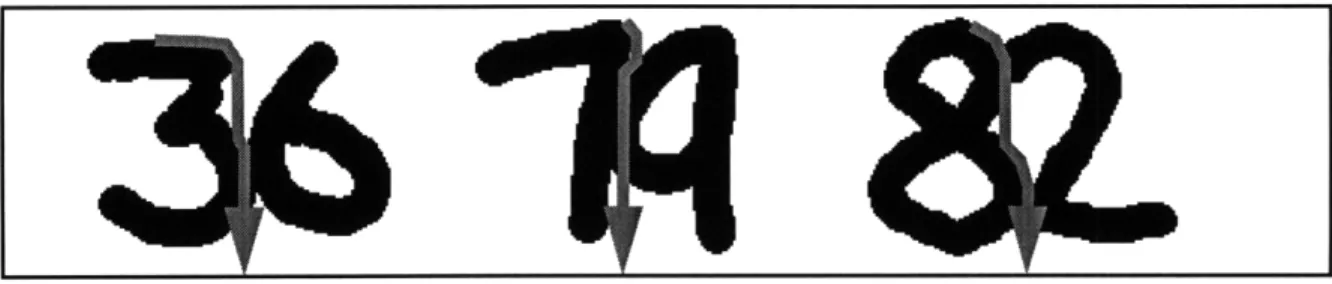
Figure 15: Examples for which the top-left drop fall segmentation heuristic fails
As seen from Figure 14, the top-left drop fall tends to work well in cases when the point at which the two characters are joined are a minimum point and it fails when it is not. From Figure
15, we can see that the heuristic will usually fail either when a minimum point does not occur at
the point of connection or overlap of the two characters (as is the case with the '95' and '73') or the point of initiation (where the drop fall starts from) is not close enough to the point where the two characters touch (for example, the '46' in Figure 15). The second of the two failures can be corrected by formulating more advanced heuristics for deciding where to initiate the drop fall from. Once such heuristic would be to give preference to candidate initiation points which are closer to the center of the image. It is much harder, however, to make corrections for failures of
the first type which tends to happen anytime the second character is a 3 or 5 since both of these numbers have a minimum on their lower strokes which are accessible to the drop fall algorithm (An 8 has a minimum on its lower stroke, but the drop fall algorithm not get to it since its lower stroke is closed). Using other varieties of the drop fall heuristic (top-right, bottom-left, and bot-tom-right) we will see that it may be possible to correct these failures.
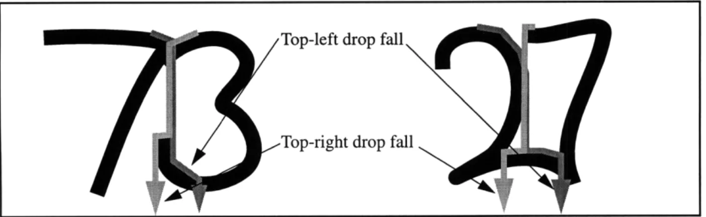
The top-right drop fall tends to succeed and fail on the same cases as the standard top-left algorithm. There are however, some special cases when one can succeed and the other fails (Fig-ure 16). However, these cases tend to be very concocted, so for all general purposes they are equivalent in terms of effectiveness.
Top-left drop fall
Top-right drop fall
Figure 16: Examples of when top-right and top-right drop-fall differ in results
As mentioned earlier, the drop falls which start from the bottom of the image (bottom-left and bottom-right) tend to succeed in most of the cases where the top-based drop falls fail (Figure 15). They also, however, fail on some examples that the top-based drop falls would segment prop-erly (Figure 16). Based on the fact that the top-based and bottom-based drop falls 'complement' each other, it is clear that a heuristic which makes use of both of them could potentially be
4.4 Hybrid drop fall heuristic
Based on the evaluation of the four variations of the drop fall described in the previous section, it is clear that each has advantages over the other. In particular, the top-based and the bot-tom-based downfalls can each successfully segment cases that the other can't. With this in mind, we will design a hybrid drop fall heuristic which combines the best of both types of elements.
The algorithm will initially attempt a top-left drop fall on the image. Then it will attempt to determine if the algorithm performed a successful segmentation. In order to cover as many cases as possible, the hybrid algorithm needs to be able to recognize when one variety of the drop fall fails in order to know when to use one of the other variations. We could potentially use a character recognizer at this point to determine if each of the resulting characters are legible numeral. This, however, would be computationally expensive and would not necessarily even give a good indication of the quality of the segmentation. Instead, we will make use of the some of the observations about cases where the top-right drop fall fails we made in the last sections to
determine whether or not the segmentation was successful. Lower strokes
with minima
points cause the top-left drop fall
to fail.
Figure 17: Concave lower strokes on characters like '3' and '5' cause the top-left drop-fall algorithm to fail. As we saw in the previous section and can see in Figure 17, the top left drop-fall tends to fail when the second character has a local minima in its lower stroke. This is true for all threes and fives. Since we cannot know a priori whether or not the second digit is a three or five, some
other means for recognizing such a failure has to be established. If we look at the minima of lower strokes of characters versus the minima at the junction point between two characters, there is one fundamental difference-- the minima at the lower stroke of a three or five tends to be very gradual and flat while the minima at the junction point between two characters tends to be very
sharp and steep (Figure 18). Based on this observation, all that the algorithm would need to do is recognize whether the minima at which the top-left drop fall begins to cut into the characters is sharp and steep or flat and gradual. If it is sharp and steep, then the top-left drop fall is most prob-ably sufficient. On the other hand, if the minima is flat, then the top-left drop fall probprob-ably failed by cutting through the lower stroke of a three or five. In this case, a bottom-right drop fall will be applied. As we saw in the previous section, the bottom-right drop fall usually properly segments cases such as the one described when a top-left drop fall would fail.
Sharp and steep
Gradual and minima
flat minima
Figure 18: Differences between minima on the lower stroke of characters and minima at the junction of two characters.
Even though we know that the top-left drop fall tends to fail when it begins to cut at a flat minima and that it tends to succeed when it cuts at a steep minima, a method for recognizing steep versus flat minima must be developed. The best way to do this would be to travel along the con-tour of the characters a given number of pixels to the left and to the right. If the concon-tour rises in either direction more than a certain threshold than it is classified as being steep. If it does not, then it is flat (Figure 19). Between 3 and 5 pixels should be travelled in each direction along the
contour, depending on the size of the image. The threshold should be half the number of pixels travelled. Based on this, if the slope in either direction is greater than 1/2, then it is steep. Other-wise, it is flat.
Flat search countour 5 pixels Steep
in each direction threshold
minima where the drop-fall will cut
Figure 19: Using the slope of the neighboring contour to determine if the minima is at a 'steep' or a 'flat' point
Figure 20: Performing bottom-right drop fall when top-left drop-fall is recognized to fail
V
Top-left drop fallmakes cut at 'flat' minima -> top-left drop fall is not successful.
Chapter
5:
Development and Design of the Segmentation Toolbox
The ideas described in this thesis were implemented into a segmentation workbench affec-tionately called the Segmentor. It is a graphical application whose main purpose is to ease exper-imentation with various heuristics for segmentation. Having a stand alone application dedicated to segmentation dramatically reduces the complexity of changing the methods for segmentation. Not only that, but experimenting within the context of a optical character recognition system could potentially break the entire system. For example, if the recognizer portion of the system is neural-net based, then modifying one heuristic in the segmentation process may force you to retrain the entire neural net as well. Both the Segmentor's graphical user interface as well as its underlying code were implemented in Matlab.
5.1 Functionality of the segmentation tool box
The Segmentor's main utility lies in its ability to provide any easy way to experiment with methods for segmentation. Its design is focused around the following three features:
* Flexibility: As mentioned above, the main purpose of building the Segmentor in the first place was to provide an easy way to test various segmentation methods. Because of this, it is of prime importance that the system be made flexible. This issue is addressed in the design of the Segmentor by allowing the user to add or define his own image formats; change the algo-rithms used for any step of the segmentation process; and easily incorporate the Segmentor routines into another application. In fact, the system is designed to allow users to either use the predefined graphical user interface or prototype their own.
* Extensibility: The system would be of little future use if future users cannot add on their own routines and functionality. The Segmentor takes this into consideration by allowing users to
add on new routines, modify current routing, and add completely new modules to the Segmen-tor.
* Ease of use: In order to optimize the usefulness of the segmentor, much consideration was taken to ensure that it is easy to use, modify, and add on to. To a large degree, the extensibility
and structure of Matlab's pre-defined graphical user interface library makes this possible. The design of the system is also extremely modular so as to allow components and routines to be easily replaced and modified.
Within the above-mentioned design considerations, the Segmentor will allow user to do anything from performing a single segmentation step to the entire segmentation process on a char-acter string image. It also allows the user to dynamically change variables used for segmentation without modifying any code. Here are three scenarios depicting possible uses for the Segmentor: * If a user wishes to build and test a new algorithm to dynamically threshold a character string
image, then the Segmentor could significantly reduce the work involved. First, in order to get an estimate of what threshold values work best for which type of images, the user could dynamically adjust the threshold value (using the left-most slider control depicted in Figure 21) and repeatedly perform connected component analysis. Doing this will allow the user to get a 'feel' for the task. Then, he or she could develop a prototype matlab function which implements a thresholding algorithm and connect the function to one of the workbench but-tons. Critical variables in the algorithm can then be assigned to the slider so as to allow dynamic modification of the variables without modifying the code. Also, the inputs and the outputs of the algorithm could be easily viewed and manipulated.
* Another use of the Segmentor would be to compare various segmentation algorithms with each other. In this case the user could load an array of test images into the segmentor and then
apply the two algorithms to all of the images. The resulting segmented images could then be displayed side by side for each of the algorithms.
* With the scope of the research performed in this thesis, the Segmentor was used to prototype a new hybrid, drop fall algorithm. Using the Segmentor allowed the algorithm to be developed relatively quickly without having to repeatedly recompile code or worry about unwanted side effects on other components of a handwriting recognition system. Only after the algorithm was developed and tested using the Segmentor, was it hardcoded in C++ into the complete handwriting recognition system.
5.2 Structure and implementation of the graphical user interface
The Segmentor's main purpose is to be an easy to use application for studying segmenta-tion heuristics. With this goal in mind, it is of utmost importance that its interface be intuitive and
simple. The interface consists of a main menu, a controls area, and a display area. The main menu contains options which allow the user to select new image files, print the display, or exit the appli-cation. The image file selected from the menu will be the one used in all future operations. The controls area is where the user is allowed to define segmentation steps and control the entire pro-cess in general. Using the controls in this area, the user is able to step through various segmenta-tion steps, and manipulate thresholds and other variables involved in segmentasegmenta-tion. Finally, the
Figure 21: Image of the Segmentor's graphical user interface
5.3 Image formats and representations
The Segmentor tool box is capable of reading any of the standard image formats as the inputs, including JPEGS, TIFFs, and BMPs. The images are read using the imread (part of the matlab image manipulation library) utility in matlab which can convert any of the aforementioned image formats to Matlab matrices. In designing the tool box, an assumption is made that the images used will be only of the courtesy amount and not include any extraneous noise or charac-ters. This assumption can be made due to the fact that there are already well-established
algo-rithms for locating the courtesy amount on a check [2]. It is also assumed that the input image is a 256-shade gray scale image.
5.4 Implementation of connected component finder
The first step in segmenting any character string is to separate out the connected compo-nents. This is the most basic, and potentially most important step. Ideally, if all of the characters are well-spaced, then finding the connected components would be equivalent to segmenting the whole string. In the Segmentor application, connected components were identified using basic search algorithm.
The image is first scanned column-by-column to identify the first white pixel. A non-white pixel is recognized to be any pixel with an intensity less than 100. This threshold value can either manually set or dynamically adjusted depending on the average intensity and contrast of the image. The image is scanned column-by-column as opposed to row-by-row to maximize the chances that the first pixel encountered belongs to the first digit of the character string (Figure 21). The only time that this may not work properly is if the top stroke of a 7 completely covers the pre-ceding character (Figure 22).
Once the initial black pixel is found, a bread first search is performed to identify all of the pixels connected to it. For the purposes of the breadth-first search, a pixel is considered connected to another pixel if it lies directly above, below, to the right, or to the left of the given pixel. Two pixels lying diagonal to each other are not immediately identified as being connected due to the
common case depicted in Figure 23. Also, it is unlikely that two pixels are from the same charac-ter if they are only diagonal to each other (i.e. they share no other neighbors).
Figure 22: Scanning method fails only in the unusual case of a '7' hanging completely over the preceding char-acter. This is compensated for by deciding character position by the centroid of their respective bounding
boxes.
These 2 pi els should not be
classificd as being part of the same c\nnected component.
Figure 23: Search algorithm does not move to diagonal pixels to avoid the case where characters are only con-nected by diagonal pixels
The breadth-first search routine (see Appendix) operates by tagging each connected pixel it encounters and copying it into a buffer the same size of the original image. It also keeps track of the bounding box of the connected component. The routine suspends once it cannot find any new connected pixels. At this point, it crops the buffer based on the size of the bounding box.
Finally, it returns, the bounding box of the connected region, the modified image (with all of the connected pixels tagged) and the cropped copy of the connected region.
The connected component finder then continues to scan the image in the manner described above until it encounters another black pixel (which has not been tagged by the bread-first-search routine). The search routine is then executed again on this pixel, resulting in a new connected component. The cropped image of each new connected component is stored in an indexed table to facilitate further processing. This process is repeated until every pixel of the image has been scanned by the connected component finder.
5.5 Heuristic for recognizing and connecting disjointed fives
One of the most common occurrences of a numerical character being broken into two con-nected components is when the top stroke of a '5' is disjointed from the body of the numeral (Fig-ure 24).
disjointed top stroke
Figure 24: Example of a '5' with a disjointed top stroke
The Segmentor uses a simple heuristic which makes use of the size and position informa-tion of the connected components to make a decision as to whether a given connected component
is a disjointed top stroke of a 5. The first test used is the aspect ratio (The ratio of the height to the width) of the connected component. If the width is greater than two times the height, then the component is candidate for being a disjointed top stroke of a 5. Then, if the component is
1/3 the size of the previous component and is completely contained in the top half of the image, it is considered to be a disjointed top half of a 5. The logic behind the heuristic is as follows: * If the width of a connected component is greater than its height, then the component can either
be two or more connected components, an extremely slanted comma, a wide decimal point, a disjointed top stroke of a five, or the divider between the numerator and denominator of the cent field of the number (Figure 25).
Figure 25: Examples of connected components for which the height is less than the width
* If the component is one-third the height of the previous character, then the possibility that it is two or more connected characters can be ruled out (It would be extremely unusual for one entire character to be less than one third the height of the previous character).
* Finally, if the component is completely contained within the upper half of the image, then the probability that it is a comma, period, or division character of cent field is extremely low. There are special cases where the division sign of the cent field can meet the above criteria. To prevent such a character from being recognized as a disjointed top stroke of a 5, an added check can be made as to whether any other connected components are contained entirely
above the character (Only the division character in the cent field would have connected com-ponents contained entirely above it-- namely, the numerator).
Once a component has met the above-defined criteria, and thus is classified as being the disjointed top stroke of a five, it is pasted on top of the previous component so that they are later processed together as one character. In order to optimize the recognition of the disjointed five later on, a connection routine could be used to connect the top stroke with the rest of the five. Currently, such a connection routine is not implemented in the Segmentor, but a possible imple-mentation of it could be as follows (Figure 26):
1. Identify the left-most pixel of the top stroke of the five.
2. Identify the maximum point on the body of the five which is closest to the point identified in step 1.
3. Connect the two points with a width equivalent to the height of the top stroke.
The above defined heuristics are extremely robust and only fail in very unlikely instances. The performance and examples of the type of connected components on which it would fail are described in more detail in the results chapter.
Top stroke of '5' eft-most pixel of the top stroke of the '5'
Connection between the top stroke and main body of axima on the body of the '5' located closest to the top
the '5'
stroke
Enlarged depiction of the 'bridge' formed between the main body and disjointed top stroke of a '5'. Main
body \ of '5'
Once all of the connected components are identified and any disjointed top strokes of '5's are connected, the connected component finder module displays both the original image and an image of the connected components separated by a divider.
5.6 Heuristics for recognizing touching or overlapping characters
Currently, the best available methods for determining whether a connected component consists of two or more overlapping characters make use of the component's aspect ratio and posi-tion. The aspect ratio, or the width of the image to the height, tends to be greater than 1 for con-nected characters and less than 1 for single characters. Since, as mentioned in the previous section, other characters such as divider between the numerator and denominator of the cent field and a disjointed top-stroke of a five can have an aspect ratio greater than 1 as well, the position and size of the connected component are used as well to decide if the component is made up of multiple touching characters.
This procedure is implemented in the Segmentor as follows. As mentioned in Section 5.4, the connected component finder module of the Segmentor outputs the connected components in an indexed table. This table is then passed to the module which identifies which components are made up of touching or overlapping characters. This procedure then loops through the table, checking whether any of the aspect ratios are greater than 1. If they are, then the procedure checks the size of the bounding box. If the bounding box's area is greater than 500, then the com-ponent is classified as being composed of two touching or overlapping characters. For the sake of simplicity, the assumption is made that more than two touching or overlapped characters will not be encountered. The current method could be extended to the more general multiple-character case by including more clauses to which would consider even larger bounding box areas. The procedure then adds the index of that component to a newly created table which keeps track of
which of the components need to be further processed. These components are then passed on to the module which attempts to perform the hybrid drop fall algorithm described in Chapter 3 on them.
5.7 Techniques for splitting connected characters
The Segmentor uses the hybrid drop-falling algorithm described in the previous chapter in order to segment connected characters. The module which takes care of this is passed the indexed table of connected components produced by the connected component finder as well as the table described in the previous section which indexes the connected components which need to be
fur-ther segmented. The drop fall algorithm is then performed on each of these connected components as follows:
1. A one dimensional array, cut[], which has length equal to the height of the image, is initialized. This array will store the pixels which represent the border between the two connected charac-ters.
2. The image is scanned row-by-row until a black border pixel separated from another black pixel to the right of it by only white space (Figure 9) is identified. The x-coordinate of that pixel is stored in cut[y-coordinate of pixel]. Since there should be nothing but white space above this pixel, cut[ 1, 2, ..., y-coordinate of pixel] is set to equal the x-coordinate of the pixel.
3. A top left drop fall commences from this pixel as described by Figure 10. The x-coordinate of each new pixel in the drop fall is stored in cut[ y-coordinate of current pixel]. If there is already an x-coordinate written in that position in the array, then it is overwritten.
4. The drop fall continues until it reaches a minimum at which point it must begin to 'cut' into the black pixels below it. The algorithm will then traverse the border six pixels (the number of pix-els traversed can be dynamically changed using one of the sliders on the graphical user inter-face) to the left and right. If the contour has risen by three or more pixels in either direction then the top-left drop fall continues. Otherwise, the cut array is reinitialized and a bottom-right drop
fall algorithm is called.
5. If the algorithm continues, it will continue to drop fall as described in Figure 10 until it reaches the bottom of the image. The cut[] array will have a value for everyone of its entries at this point.
6. A blank image with height equal to the height of the connected component image and width equal to the maximum value in cut[] is created. The connected component image will be scanned row by row. For each pixel in a row, if it has an x-coordinate value less than the entry in the cut array for that row, then it is copied into the blank image. That pixel will also be erased
from the connected component image.
7. The connected component image is cropped so as to only include the bounding box of what is left of the connected component.
8. At this point the first character will be in the image created in step 6 and the second character will be in the cropped version of the connected component image.
The top-right drop fall algorithm described in step 5 uses Matlab's matrix operations to reverse the indices of the image matrix in both height and width directions (In effect, flipping the image over on its vertical axis and then flipping it on its horizontal axis). It then performs essen-tially the top-left drop fall algorithm performed in steps 1-9 above without the check to see the
When the top-left drop fall algorithm encounters a minima, it has to decide the 'concativ-ity' of the minima (Step 4). This is done using a contour following procedure. First this performs the following steps which traverse the contour to the right:
1. If there is a white pixel to the right of the current pixel, then the algorithm sets the set the cur-rent pixel to the pixel to the right. Otherwise, the algorithm scans every pixel directly above that pixel until it find a white pixel and assigns that to be the current pixel.
2. Step 1 is repeated 5 times or until the current pixel rises more than three pixels.
3. If the current pixel rises more than 3 pixels, then the routine is done. Otherwise, it repeats steps 1 and 2 to the left.
Once it was built and test using the segmentation toolbox, the hybrid drop fall segmenta-tion heuristic was implemented as part of a larger check amount verificasegmenta-tion system called Win-Bank (See appendix for code). This incarnation of the algorithm was written in C++, but concept-wise is identical to the algorithm described above.
Chapter 6: Implementation of Hybrid Algorithm within WinBank
WinBank is a system developed at MIT's Sloan School of management with the intent of automatically verifying check amounts. As with most handwriting recognition systems, WinBank consists of several preprocessing stages which include character segmentation, a neural net based recognition engine, and well as several post-processing stages. Since the hybrid drop fall algo-rithm developed in this thesis focuses only on segmentation and WinBank is a relatively large and complex system, we will look only at the way that WinBank currently handles only this process.
WinBank currently employs two waves of segmentation heuristics to connected compo-nents composed of two characters. The first of these is a min-max based procedure and the
sec-ond is a particular type of hit and deflect heuristic. The hybrid drop fall algorithm is incorporated into the system as an optional third wave heuristic. This chapter will focus on how segmentation is currently done in WinBank, how the hybrid algorithm is implemented, and the benefits of hav-ing the hybrid algorithm in the system.
6.1 The min-max based algorithm
As part of a first attempt at segmenting a connected component into two numeric charac-ters, the WinBank system uses a min-max algorithm. The particular version used in WinBank is min-max in its simplest form. The routine first scans the upper and lower profiles of the con-nected component within some deviation limit to both sides of the center of the image. It then stores the minimum and maximum values of the upper and lower contours, respectively. These values are then passed to a 'bridging' routine which attempts to join the two point with a path that traverses at most two black-to-white or white-to-black transitions. In constructing the path, the routine also attempts to avoid having the resulting separated components having irregular aspect
ratios. If the procedure cannot find a path under these constraints, then it quits. In fact, it even quits if the minimum point on the upper contour is lower than the maximum point on the lower contour.
6.2 The hit and deflect algorithm
The WinBank system turns to a variation of the hit and deflect strategy when the min-max does not prove to be successful. This implementation is very similar to the standard drop fall algorithms discussed in previous chapters accept that it varies by one rule. In the drop fall algo-rithms, if the current pixel is 'blocked' from below, but not from the sides, it will move to one side or another. The hit and deflect algorithm implemented in Winbank will 'cut' into the pixels below it instead. For most cases, however, the algorithm produces similar results as a standard top-left drop fall. Just as with the min-max algorithm, this algorithm attempts to find a suitable path within dimensions constraints on the resulting segments.
6.3 Implementation of the hybrid drop fall algorithm
The hybrid drop fall algorithm described in Chapter 4 was implemented into the WinBank system as an optional third pass algorithm for improving segmentation (See appendix A.7 for code). Based on the arguments passed to the drop fall routine, it is capable of performing a top-left, top-right, bottom-top-left, or bottom-right drop fall. The routine will return both a segmentation path and the 'flatness' at the point where the routine 'cuts' into the connected component. In order to implement the hybrid routine, the routine should first be called with arguments to make it perform a top left drop fall. Then, if the routine returns a flatness below a given threshold, it
Fig-ure 26 shows examples of when the hybrid drop fall algorithm as implemented in WinBank will outperform the hit and deflect and min-max algorithms.
Figure 26: The max and Hit and Deflect (light gray arrows) fail on every one of these examples. The min-max fail because in every case the minimum on the upper contour is lower than the min-maximum of the lower